Cisco Industrial Ethernet 4000, 4010 and 5000 Switch Software. Configuration Guide (2022) - page 28

Configuring IP Multicast Routing
Configuring Optional IGMP Features
DETAILED STEPS
Command
Purpose
1.
configure terminal
Enter global configuration mode.
2.
interface interface-id
Specify the interface to be configured, and enter interface
configuration mode.
3.
no shutdown
Enable the port, if necessary. By default, UNIs and ENIs are
disabled, and NNIs are enabled.
4.
ip igmp access-group
Specify the multicast groups that hosts on the subnet
access-list-number
serviced by an interface can join.
By default, all groups are allowed on an interface.
For access-list-number, specify an IP standard access list
number. The range is 1 to 99.
5.
exit
Return to global configuration mode.
6.
access-list access-list-number {deny
Create a standard access list.
| permit} source [source-wildcard]
For access-list-number, specify the access list created
in Step 3.
The deny keyword denies access if the conditions are
matched. The permit keyword permits access if the
conditions are matched.
For source, specify the multicast group that hosts on the
subnet can join.
(Optional) For source-wildcard, enter the wildcard bits in
dotted decimal notation to be applied to the source.
Place ones in the bit positions that you want to ignore.
Recall that the access list is always terminated by an implicit
deny statement for everything.
7.
end
Return to privileged EXEC mode.
8.
show ip igmp interface [interface-id]
Verify your entries.
9.
copy running-config startup-config
(Optional) Save your entries in the configuration file.
To disable groups on an interface, use the no ip igmp access-group interface configuration command.
EXAMPLE
This example shows how to configure hosts attached to a port as able to join only group 255.2.2.2:
Switch(config)# access-list 1 255.2.2.2 0.0.0.0
Switch(config-if)# interface gigabitethernet0/1
Switch(config-if)# ip igmp access-group 1
Changing the IGMP Version
By default, the switch uses IGMP Version 2, which provides features such as the IGMP query timeout and the maximum
query response time.
757

Configuring IP Multicast Routing
Configuring Optional IGMP Features
All systems on the subnet must support the same version. The switch does not automatically detect Version 1 systems
and switch to Version 1. You can mix Version 1 and Version 2 hosts on the subnet because Version 2 routers or switches
always work correctly with IGMPv1 hosts.
Configure the switch for Version 1 if your hosts do not support Version 2.
This procedure is optional.
BEFORE YOU BEGIN
Review the Information About IGMP, page 718.
DETAILED STEPS
Command
Purpose
1.
configure terminal
Enter global configuration mode.
2.
interface interface-id
Specify the interface to be configured, and enter interface
configuration mode.
3.
no shutdown
Enable the port, if necessary. By default, UNIs and ENIs are
disabled, and NNIs are enabled.
4.
ip igmp version {1 | 2}
Specify the IGMP version that the switch uses.
Note: If you change to Version 1, you cannot configure the ip
igmp query-interval or the ip igmp
query-max-response-time interface configuration
commands.
5.
end
Return to privileged EXEC mode.
6.
show ip igmp interface [interface-id]
Verify your entries.
7.
copy running-config startup-config
(Optional) Save your entries in the configuration file.
To return to the default setting, use the no ip igmp version interface configuration command.
EXAMPLE
The following example configures the router to use IGMP Version 2:
ip igmp version 2
Modifying the IGMP Host-Query Message Interval
The switch periodically sends IGMP host-query messages to discover which multicast groups are present on attached
networks. These messages are sent to the all-hosts multicast group (224.0.0.1) with a time-to-live (TTL) of 1. The switch
sends host-query messages to refresh its knowledge of memberships present on the network. If, after some number of
queries, the software discovers that no local hosts are members of a multicast group, the software stops forwarding
multicast packets to the local network from remote origins for that group and sends a prune message upstream toward
the source.
The switch elects a PIM designated router (DR) for the LAN (subnet). The DR is the router or multilayer switch with the
highest IP address for IGMPv2. For IGMPv1, the DR is elected according to the multicast routing protocol that runs on
the LAN. The designated router is responsible for sending IGMP host-query messages to all hosts on the LAN. In sparse
mode, the designated router also sends PIM register and PIM join messages toward the RP router.
This procedure is optional.
758

Configuring IP Multicast Routing
Configuring Optional IGMP Features
BEFORE YOU BEGIN
We recommend that you do not modify the IGMP query interval and IGMP querier timeout values. However, if you
configure the appropriate commands to change the query interval and querier timeout default values, the following
conditions apply:
If you use the ip igmp query-interval command to configure the query interval, the timeout value is automatically
adjusted to two times the query interval; the adjusted timeout value, however, is not reflected in the interface
configuration.
Note: To confirm that the timeout value adjusted to two times the modified query interval, use the show ip igmp interface
command to display the query interval and timeout values being used for the interface.
Conversely, if you use the ip igmp querier-timeout command to configure the timeout value, the query interval does
not automatically adjust to half of the modified timeout value, so it is possible to override the default timeout period
of two times the query interval. If you must configure the timeout period, we recommend that you configure the
timeout value in proportion to the query interval value.
The query interval must be greater than the IGMP maximum query response time. Use the ip igmp
query-max-response-time command to change the maximum query response time value from the default (10
seconds) to a specified length of time, if required.
DETAILED STEPS
Command
Purpose
1.
configure terminal
Enter global configuration mode.
2.
interface interface-id
Specify the interface to be configured, and enter interface
configuration mode.
3.
no shutdown
Enable the port, if necessary. By default, UNIs and ENIs are
disabled, and NNIs are enabled.
4.
ip igmp query-interval seconds
Configure the frequency at which the designated router sends
IGMP host-query messages.
By default, the designated router sends IGMP host-query
messages every 60 seconds to keep the IGMP overhead very
low on hosts and networks. The range is 1 to 65535.
5.
end
Return to privileged EXEC mode.
6.
show ip igmp interface
Verify your entries.
[interface-id]
7.
copy running-config
(Optional) Save your entries in the configuration file.
startup-config
To return to the default setting, use the no ip igmp query-interval interface configuration command.
EXAMPLE
The following example shows how to configure the switch to wait 240 seconds from the time it received the last query
before it triggers the IGMP election process. In this example, the timeout period is manually modified in proportion to the
IGMP query interval by using the ip igmp querier-timeout command.
interface GigabitEthernet1/17
ip igmp query-interval 120
ip igmp querier-timeout 240
759
Configuring IP Multicast Routing
Configuring Optional IGMP Features
The following example shows how to configure the switch to wait 250 seconds from the time it received the last query
until the time that it triggers the IGMP election process. When the timeout value is explicitly configured, the query interval
does not automatically adjust. Because the query interval was not explicitly configured to change the default value (60
seconds), the default timeout period of two times the query interval, or 120 seconds, is overridden by the specified value.
interface GigabitEthernet0/1
ip igmp querier-timeout 250
Changing the IGMP Query Timeout for IGMPv2
If you are using IGMPv2, you can specify the period of time before the switch takes over as the querier for the interface.
By default, the switch waits twice the query interval controlled by the ip igmp query-interval interface configuration
command. After that time, if the switch has received no queries, it becomes the querier.
You can configure the query interval by entering the show ip igmp interface interface-id privileged EXEC command. This
procedure is optional.
BEFORE YOU BEGIN
We recommend that you do not modify the IGMP query interval and IGMP querier timeout values. However, if you
configure the appropriate commands to change the query interval and querier timeout default values, the following
conditions apply:
If you use the ip igmp query-interval command to configure the query interval, the timeout value is automatically
adjusted to two times the query interval; the adjusted timeout value, however, is not reflected in the interface
configuration.
Note: To confirm that the timeout value adjusted to two times the modified query interval, use the show ip igmp interface
command to display the query interval and timeout values being used for the interface.
Conversely, if you use the ip igmp querier-timeout command to configure the timeout value, the query interval does
not automatically adjust to half of the modified timeout value, so it is possible to override the default timeout period
of two times the query interval. If you must configure the timeout period, we recommend that you configure the
timeout value in proportion to the query interval value.
The query interval must be greater than the IGMP maximum query response time. Use the ip igmp
query-max-response-time command to change the maximum query response time value from the default (10
seconds) to a specified length of time, if required.
760

Configuring IP Multicast Routing
Configuring Optional IGMP Features
DETAILED STEPS
Command
Purpose
1.
configure terminal
Enter global configuration mode.
2.
interface interface-id
Specify the interface to be configured, and enter interface
configuration mode.
3.
no shutdown
Enable the port, if necessary. By default, UNIs and ENIs are
disabled, and NNIs are enabled.
4.
ip igmp querier-timeout seconds
Specify the IGMP query timeout.
The default is 60 seconds (twice the query interval). The range
is 60 to 300.
5.
end
Return to privileged EXEC mode.
6.
show ip igmp interface
Verify your entries.
[interface-id]
7.
copy running-config
(Optional) Save your entries in the configuration file.
startup-config
To return to the default setting, use the no ip igmp querier-timeout interface configuration command.
EXAMPLE
The following example shows how to configure the switch to wait 240 seconds from the time it received the last query
before it triggers the IGMP election process. In this example, the timeout period is manually modified in proportion to the
IGMP query interval by using the ip igmp querier-timeout command.
interface GigabitEthernet1/17
ip igmp query-interval 120
ip igmp querier-timeout 240
The following example shows how to configure the switch to wait 250 seconds from the time it received the last query
until the time that it triggers the IGMP election process. When the timeout value is explicitly configured, the query interval
does not automatically adjust. Because the query interval was not explicitly configured to change the default value (60
seconds), the default timeout period of two times the query interval, or 120 seconds, is overridden by the specified value.
interface GigabitEthernet0/1
ip igmp querier-timeout 250
Changing the Maximum Query Response Time for IGMPv2
If you are using IGMPv2, you can change the maximum query response time advertised in IGMP queries. The maximum
query response time enables the switch to quickly detect that there are no more directly connected group members on
a LAN. Decreasing the value enables the switch to prune groups faster.
This procedure is optional.
BEFORE YOU BEGIN
The query interval (see the Modifying the IGMP Host-Query Message Interval, page 758) must be greater than the IGMP
maximum query response time.
761

Configuring IP Multicast Routing
Configuring Optional IGMP Features
DETAILED STEPS
Command
Purpose
1.
configure terminal
Enter global configuration mode.
2.
interface interface-id
Specify the interface to be configured, and enter interface
configuration mode.
3.
no shutdown
Enable the port, if necessary. By default, UNIs and ENIs are
disabled, and NNIs are enabled.
4.
ip igmp
Change the maximum query response time advertised in IGMP
query-max-response-time
queries.
seconds
The default is 10 seconds. The range is 1 to 25.
5.
end
Return to privileged EXEC mode.
6.
show ip igmp interface
Verify your entries.
[interface-id]
7.
copy running-config
(Optional) Save your entries in the configuration file.
startup-config
To return to the default setting, use the no ip igmp query-max-response-time interface configuration command.
EXAMPLE
The following example configures a maximum response time of 8 seconds:
ip igmp query-max-response-time 8
Configuring the Switch as a Statically Connected Member
Sometimes there is either no group member on a network segment or a host cannot report its group membership by
using IGMP. However, you might want multicast traffic to go to that network segment. These are ways to pull multicast
traffic down to a network segment:
Use the ip igmp join-group interface configuration command. With this method, the switch accepts the multicast
packets in addition to forwarding them. Accepting the multicast packets prevents the switch from fast switching.
Use the ip igmp static-group interface configuration command. With this method, the switch does not accept the
packets itself, but only forwards them. This method enables fast switching. The outgoing interface appears in the
IGMP cache, but the switch itself is not a member, as evidenced by lack of an L (local) flag in the multicast route entry.
This procedure is optional.
BEFORE YOU BEGIN
If you configure the ip igmp join-group command for the same group address as the ip igmp static-group command,
the ip igmp join-group command takes precedence, and the group behaves like a locally joined group.
762

Configuring IP Multicast Routing
Configuring Optional Multicast Routing Features
DETAILED STEPS
Command
Purpose
1.
configure terminal
Enter global configuration mode.
2.
interface interface-id
Specify the interface to be configured, and enter interface
configuration mode.
3.
no shutdown
Enable the port, if necessary. By default, UNIs and ENIs are
disabled, and NNIs are enabled.
4.
ip igmp static-group group-address
Configure the switch as a statically connected member of a
group.
By default, this feature is disabled.
5.
end
Return to privileged EXEC mode.
6.
show ip igmp interface
Verify your entries.
[interface-id]
7.
copy running-config startup-config
(Optional) Save your entries in the configuration file.
To remove the switch as a member of the group, use the no ip igmp static-group group-address interface configuration
command.
EXAMPLE
The following example shows how to configure group address 239.100.100.101 on Ethernet interface 0:
interface ethernet 0
ip igmp static-group 239.100.100.101
Configuring Optional Multicast Routing Features
This section includes the following topics:
Configuring Session Directory Announcement Support, page 763 (optional)—for MBONE multimedia conference
session and set up
Configuring an IP Multicast Boundary, page 765 (optional)—to control bandwidth utilization.
Configuring Session Directory Announcement Support
The MBONE (multicast backbone of the Internet) is the small subset of Internet routers and hosts that are interconnected
and capable of forwarding IP multicast traffic. Other multimedia content is often broadcast over the MBONE. Before you
can join a multimedia session, you need to know what multicast group address and port are being used for the session,
when the session is going to be active, and what sort of applications (audio, video, and so forth) are required on your
workstation. The MBONE Session Directory Version 2 (sdr) tool provides this information. This freeware application can
be downloaded from several sites on the World Wide Web, one of which is http://www.video.ja.net/mice/index.html.
SDR is a multicast application that listens to a well-known multicast group address and port for Session Announcement
Protocol (SAP) multicast packets from SAP clients, which announce their conference sessions. These SAP packets
contain a session description, the time the session is active, its IP multicast group addresses, media format, contact
person, and other information about the advertised multimedia session. The information in the SAP packet is displayed
in the SDR Session Announcement window.
763

Configuring IP Multicast Routing
Configuring Optional Multicast Routing Features
Enabling Listening to Session Directory Announcements
By default, the switch does not listen to session directory advertisements. Follow this procedure to enable the switch to
join the default session directory group (224.2.127.254) on the interface and listen to session directory advertisements.
This procedure is optional.
BEFORE YOU BEGIN
Enable multicast routing on the interface as described in the Configuring Basic Multicast Routing, page 731.
DETAILED STEPS
Command
Purpose
1.
configure terminal
Enter global configuration mode.
2.
interface interface-id
Specify the interface on which the well-known session directory
groups can receive and store session announcements, and enter
interface configuration mode.
3.
no shutdown
Enable the port, if necessary. By default, UNIs and ENIs are
disabled, and NNIs are enabled.
4.
ip sap listen
Enable the switch to listen to session directory announcements.
5.
end
Return to privileged EXEC mode.
6.
show running-config
Verify your entries.
7.
copy running-config
(Optional) Save your entries in the configuration file.
startup-config
To disable listening to session directory announcements, use the no ip sap listen interface configuration command.
EXAMPLE
The following example shows how to enable the switch to listen to session directory announcements:
ip routing
interface loopback 0
ip address 10.0.0.51 255.255.255.0
ip pim sparse-dense mode
ip sap listen
Limiting How Long an SAP Cache Entry Exists
You can limit how long an SAP entry remains active so that if a source stops advertising SAP information, old
advertisements are not needlessly kept. This procedure is optional.
BEFORE YOU BEGIN
Setting the cache timeout to a value less than 30 minutes is not recommended.
764

Configuring IP Multicast Routing
Configuring Optional Multicast Routing Features
DETAILED STEPS
Command
Purpose
1.
configure terminal
Enter global configuration mode.
2.
ip sap cache-timeout minutes
Limit how long an SAP cache entry stays active in the cache.
By default, session announcements remain for 1440 minutes (24
hours) in the cache.
For minutes, the range is 1 to 4294967295.
3.
end
Return to privileged EXEC mode.
4.
show running-config
Verify your entries.
5.
copy running-config
(Optional) Save your entries in the configuration file.
startup-config
To return to the default setting, use the no ip sap cache-timeout global configuration command. To delete the entire
cache, use the clear ip sap privileged EXEC command.
To display the session directory cache, use the show ip sap privileged EXEC command.
EXAMPLE
The following example causes SAP cache entries to remain in the cache for 30 minutes:
ip sap cache-timeout 30
Configuring an IP Multicast Boundary
Administratively-scoped boundaries can be used to limit the forwarding of multicast traffic outside of a domain or
subdomain. This approach uses a special range of multicast addresses, called administratively-scoped addresses, as
the boundary mechanism. If you configure an administratively-scoped boundary on a routed interface, multicast traffic
whose multicast group addresses fall in this range cannot enter or exit this interface, thereby providing a firewall for
multicast traffic in this address range.
Note: Multicast boundaries and TTL thresholds control the scoping of multicast domains; however, TTL thresholds are
not supported by the switch. You should use multicast boundaries instead of TTL thresholds to limit the forwarding of
multicast traffic outside of a domain or a subdomain.
Figure 93 on page 766 shows that Company XYZ has an administratively-scoped boundary set for the multicast address
range 239.0.0.0/8 on all routed interfaces at the perimeter of its network. This boundary prevents any multicast traffic in
the range 239.0.0.0 through 239.255.255.255 from entering or leaving the network. Similarly, the engineering and
marketing departments have an administratively-scoped boundary of 239.128.0.0/16 around the perimeter of their
networks. This boundary prevents multicast traffic in the range of 239.128.0.0 through 239.128.255.255 from entering
or leaving their respective networks.
765

Configuring IP Multicast Routing
Configuring Optional Multicast Routing Features
Figure 93
Administratively-Scoped Boundaries
Company XYZ
Engineering
Marketing
239.128.0.0/16
239.0.0.0/8
You can define an administratively-scoped boundary on a routed interface for multicast group addresses. A standard
access list defines the range of addresses affected. When a boundary is defined, no multicast data packets are allowed
to flow across the boundary from either direction. The boundary allows the same multicast group address to be reused
in different administrative domains.
The IANA has designated the multicast address range 239.0.0.0 to 239.255.255.255 as the administratively-scoped
addresses. This range of addresses can then be reused in domains administered by different organizations. The
addresses would be considered local, not globally unique.
This procedure is optional.
BEFORE YOU BEGIN
Enable multicast routing on the interface as described in the Configuring Basic Multicast Routing, page 731.
766

Configuring IP Multicast Routing
Verifying Configuration
DETAILED STEPS
Command
Purpose
1.
configure terminal
Enter global configuration mode.
2.
access-list access-list-number
Create a standard access list, repeating the command as many
{deny | permit} source
times as necessary.
[source-wildcard]
For access-list-number, the range is 1 to 99.
The deny keyword denies access if the conditions are
matched. The permit keyword permits access if the
conditions are matched.
For source, enter the number of the network or host from
which the packet is being sent.
(Optional) For source-wildcard, enter the wildcard bits in
dotted decimal notation to be applied to the source. Place
ones in the bit positions that you want to ignore.
Recall that the access list is always terminated by an implicit
deny statement for everything.
3.
interface interface-id
Specify the interface to be configured, and enter interface
configuration mode.
4.
no shutdown
Enable the port, if necessary. By default, UNIs and ENIs are
disabled, and NNIs are enabled.
5.
ip multicast boundary
Configure the boundary, specifying the access list you created
access-list-number
in Step 2.
6.
end
Return to privileged EXEC mode.
7.
show running-config
Verify your entries.
8.
copy running-config
(Optional) Save your entries in the configuration file.
startup-config
To remove the boundary, use the no ip multicast boundary interface configuration command.
EXAMPLE
This example shows how to set up a boundary for all administratively-scoped addresses:
Switch(config)# access-list 1 deny 239.0.0.0 0.255.255.255
Switch(config)# access-list 1 permit 224.0.0.0 15.255.255.255
Switch(config)# interface gigabitethernet0/1
Switch(config-if)# ip multicast boundary 1
Verifying Configuration
This section includes the following topics:
Clearing Caches, Tables, and Databases, page 768
Displaying System and Network Statistics, page 768
Monitoring IP Multicast Routing, page 769
767

Configuring IP Multicast Routing
Verifying Configuration
Clearing Caches, Tables, and Databases
You can remove all contents of a particular cache, table, or database. Clearing a cache, table, or database might be
necessary when the contents of the particular structure are or suspected to be invalid.
Command
Purpose
clear ip igmp group [group-name |
Delete entries from the IGMP cache.
group-address | interface]
clear ip mroute {* | group [source]}
Delete entries from the IP multicast routing table.
clear ip pim auto-rp rp-address
Clear the Auto-RP cache.
clear ip sdr [group-address | “session-name”]
Delete the Session Directory Protocol Version 2
cache or an sdr cache entry.
Displaying System and Network Statistics
You can display specific statistics, such as the contents of IP routing tables, caches, and databases.
Note: This release does not support per-route statistics.
You can display information to learn resource utilization and solve network problems. You can also display information
about node reachability and discover the routing path your device’s packets are taking through the network.
768

Configuring IP Multicast Routing
Configuration Example
Command
Purpose
ping [group-name | group-address]
Send an ICMP Echo Request to a multicast group address.
show ip igmp groups [group-name |
Display the multicast groups that are directly connected to the switch
group-address | type number]
and that were learned through IGMP.
show ip igmp interface [type number]
Display multicast-related information about an interface.
show ip mcache [group [source]]
Display the contents of the IP fast-switching cache.
show ip mpacket [source-address | name]
Display the contents of the circular cache-header buffer.
[group-address | name] [detail]
show ip mroute [group-name |
Display the contents of the IP multicast routing table.
group-address] [source] [summary] [count]
[active kbps]
show ip pim interface [type number] [count]
Display information about interfaces configured for PIM.
show ip pim neighbor [type number]
List the PIM neighbors discovered by the switch.
show ip pim rp [group-name |
Display the RP routers associated with a sparse-mode multicast
group-address]
group.
show ip rpf {source-address | name}
Display how the switch is doing Reverse-Path Forwarding (that is,
from the unicast routing table or static mroutes).
show ip sap [group | “session-name” | detail]
Display the Session Directory Protocol Version 2 cache.
Monitoring IP Multicast Routing
Command
Purpose
mrinfo [hostname | address] [source-address
Query a multicast router or multilayer switch about which neighboring
| interface]
multicast devices are peering with it.
mstat source [destination] [group]
Display IP multicast packet rate and loss information.
mtrace source [destination] [group]
Trace the path from a source to a destination branch for a multicast
distribution tree for a given group.
Configuration Example
This example enables IP multicast distributed switching and specifies the PIM mode:
Switch# configure terminal
Switch(config)# ip multicast-routing distributed
Switch(config)# interface Gigabitethernet 1/0/0
Switch(config-if)# ip pim sparse-dense-mode
Switch(config-if)# end
In this example, IP multicast routing is enabled, Switch A PIM uplink port 25 is configured as a routed uplink port with
spare-dense-mode enabled. PIM stub routing is enabled on the VLAN 100 interfaces and on Gigabit Ethernet port 20
in Figure 88 on page 721:
Switch(config)# ip multicast-routing distributed
Switch(config)# interface GigabitEthernet0/25
Switch(config-if)# no switchport
Switch(config-if)# ip address 3.1.1.2 255.255.255.0
Switch(config-if)# ip pim sparse-dense-mode
Switch(config-if)# exit
769
Configuring IP Multicast Routing
Configuration Example
Switch(config)# interface vlan100
Switch(config-if)# ip pim passive
Switch(config-if)# exit
Switch(config)# interface GigabitEthernet0/20
Switch(config-if)# ip pim passive
Switch(config-if)# exit
Switch(config)# interface vlan100
Switch(config-if)# ip address 100.1.1.1 255.255.255.0
Switch(config-if)# ip pim passive
Switch(config-if)# exit
Switch(config)# interface GigabitEthernet0/20
Switch(config-if)# no switchport
Switch(config-if)# ip address 10.1.1.1 255.255.255.0
Switch(config-if)# ip pim passive
Switch(config-if)# end
To verify that PIM stub is enabled for each interface, use the show ip pim interface privileged EXEC command:
Switch# show ip pim interface
Address Interface Ver/ Nbr Query DR DR
Mode Count Intvl Prior
3.1.1.2 GigabitEthernet0/25 v2/SD 1 30 1 3.1.1.2
100.1.1.1 Vlan100 v2/P 0 30 1 100.1.1.1
10.1.1.1 GigabitEthernet0/20 v2/P 0 30 1 10.1.1.1
The following example shows how to configure a device (running IGMPv3) for SSM:
ip multicast-routing
ip pim ssm default
!
interface GigabitEthernet3/1/0
ip address 172.21.200.203 255.255.255.0
description backbone interface
ip pim sparse-mode
!
interface GigabitEthernet3/2/0
ip address 131.108.1.2 255.255.255.0
ip pim sparse-mode
description ethernet connected to hosts
ip igmp version 3
!
The following example shows how to enable static SSM mapping. In this example, the router is configured to statically
map groups that match ACL 11 to source address 172.16.8.11 and to statically map groups that match ACL 10 to source
address 172.16.8.10.
Switch(config)# ip igmp ssm-map enable
Switch(config)# ip igmp ssm-map static 11 172.16.8.11
Switch(config)# ip igmp ssm-map static 10 172.16.8.10
Switch(config)# end
The following example shows how to configure DNS-based SSM mapping:
Switch(config)# ip igmp ssm-map enable
Switch(config)# ip name-server 10.0.0.0
Switch(config)# end
The following example shows how to configure group address 239.1.2.1 to use SSM mapping for statically forwarded
groups on Ethernet interface 0:
interface ethernet 0
ip igmp static-group 239.1.2.1 source ssm-map
This example shows how to configure the address of the RP to 147.106.6.22 for multicast group 225.2.2.2 only:
770
Configuring IP Multicast Routing
Configuration Example
Switch(config)# access-list 1 permit 225.2.2.2 0.0.0.0
Switch(config)# ip pim rp-address 147.106.6.22 1
This example shows how to send RP announcements out all PIM-enabled interfaces for a maximum of 31 hops. The IP
address of port 1 is the RP. Access list 5 describes the group for which this switch serves as RP:
Switch(config)# ip pim send-rp-announce gigabitethernet0/1 scope 31 group-list 5
Switch(config)# access-list 5 permit 224.0.0.0 15.255.255.255
This example shows a sample configuration on an Auto-RP mapping agent that is used to prevent candidate RP
announcements from being accepted from unauthorized candidate RPs. In this example, the mapping agent accepts
candidate RP announcements from only two devices, 172.16.5.1 and 172.16.2.1. The mapping agent accepts candidate
RP announcements from these two devices only for multicast groups that fall in the group range of 224.0.0.0 to
239.255.255.255. The mapping agent does not accept candidate RP announcements from any other devices in the
network. Furthermore, the mapping agent does not accept candidate RP announcements from 172.16.5.1 or 172.16.2.1
if the announcements are for any groups in the 239.0.0.0 through 239.255.255.255 range. This range is the
administratively scoped address range.
Switch(config)# ip pim rp-announce-filter rp-list 10 group-list 20
Switch(config)# access-list 10 permit host 172.16.5.1
Switch(config)# access-list 10 permit host 172.16.2.1
Switch(config)# access-list 20 deny 239.0.0.0 0.0.255.255
Switch(config)# access-list 20 permit 224.0.0.0 15.255.255.255
The following example configures the interface to be the PIM domain border:
interface ethernet 1
ip pim bsr-border
This example shows a portion of an IP multicast boundary configuration that denies Auto-RP information:
Switch(config)# access-list 1 deny 224.0.1.39
Switch(config)# access-list 1 deny 224.0.1.40
Switch(config)# interface gigabitethernet0/1
Switch(config-if)# ip multicast boundary 1
This example shows how to configure a candidate BSR, which uses the IP address 172.21.24.18 on a port as the
advertised BSR address, uses 30 bits as the hash-mask-length, and has a priority of 10:
Switch(config)# interface gigabitethernet0/2
Switch(config-if)# ip address 172.21.24.18 255.255.255.0
Switch(config-if)# ip pim sparse-dense-mode
Switch(config-if)# ip pim bsr-candidate gigabitethernet0/2 30 10
This example shows how to configure the switch to advertise itself as a candidate RP to the BSR in its PIM domain.
Standard access list number 4 specifies the group prefix associated with the RP that has the address identified by a port.
That RP is responsible for the groups with the prefix 239.
Switch(config)# ip pim rp-candidate gigabitethernet0/2 group-list 4
Switch(config)# access-list 4 permit 239.0.0.0 0.255.255.255
The following example shows how to set a threshold of 4 kbps. If the traffic rate exceeds this threshold, the traffic to a
group from a source causes the router to switch to the shortest path tree to that source.
Switch# configure terminal
Switch(config)# ip pim spt-threshold 4
The following example shows how to set the PIM hello interval to 45 seconds:
interface FastEthernet0/1
ip pim query-interval 45
771
Configuring IP Multicast Routing
Related Documents
This example shows how to enable the switch to join multicast group 255.2.2.2:
Switch(config)# interface gigabitethernet0/1
Switch(config-if)# ip igmp join-group 255.2.2.2
The following example configures the router to use IGMP Version 2:
ip igmp version 2
The following example shows how to configure the switch to wait 240 seconds from the time it received the last query
before it triggers the IGMP election process. In this example, the timeout period is manually modified in proportion to the
IGMP query interval by using the ip igmp querier-timeout command.
interface GigabitEthernet1/17
ip igmp query-interval 120
ip igmp querier-timeout 240
The following example shows how to configure the switch to wait 250 seconds from the time it received the last query
until the time that it triggers the IGMP election process. When the timeout value is explicitly configured, the query interval
does not automatically adjust. Because the query interval was not explicitly configured to change the default value (60
seconds), the default timeout period of two times the query interval, or 120 seconds, is overridden by the specified value.
interface GigabitEthernet0/1
ip igmp querier-timeout 250
The following example configures a maximum response time of 8 seconds:
ip igmp query-max-response-time 8
The following example shows how to configure group address 239.100.100.101 on Ethernet interface 0:
interface ethernet 0
ip igmp static-group 239.100.100.101
The following example shows how to enable the switch to listen to session directory announcements:
ip routing
interface loopback 0
ip address 10.0.0.51 255.255.255.0
ip pim sparse-dense mode
ip sap listen
The following example causes SAP cache entries to remain in the cache for 30 minutes:
ip sap cache-timeout 30
This example shows how to set up a boundary for all administratively-scoped addresses:
Switch(config)# access-list 1 deny 239.0.0.0 0.255.255.255
Switch(config)# access-list 1 permit 224.0.0.0 15.255.255.255
Switch(config)# interface gigabitethernet0/1
Switch(config-if)# ip multicast boundary 1
Related Documents
Cisco IOS IP Multicast Command Reference
IP Multicast Configuration Guide Library, Cisco IOS Release 15M&T
Cisco IOS Master Command List, All Releases
772
Configuring MSDP
This chapter describes how to configure Multicast Source Discovery Protocol (MSDP) on the Cisco Industrial Ethernet
Switches, hereafter referred to as switch. MSDP connects multiple Protocol-Independent Multicast sparse-mode
(PIM-SM) domains.
MSDP is not fully supported in this software release because of a lack of support for Multicast Border Gateway Protocol
(MBGP), which works closely with MSDP. However, it is possible to create default peers that MSDP can operate with if
MBGP is not running.
To use this feature, the switch must be running the IP services image.
Note: For complete syntax and usage information for the commands used in this chapter, see the documents listed in
the Related Documents, page 794.
This chapter includes the following sections:
Information About MSDP, page 773
Prerequisites, page 775
Guidelines and Limitations, page 775
Default Settings, page 775
Configuring MSDP, page 775
Verifying Configuration, page 793
Configuration Example, page 793
Related Documents, page 794
Information About MSDP
MSDP allows multicast sources for a group to be known to all rendezvous points (RPs) in different domains. Each PIM-SM
domain uses its own RPs and does not depend on RPs in other domains. An RP runs MSDP over the Transmission Control
Protocol (TCP) to discover multicast sources in other domains.
An RP in a PIM-SM domain has an MSDP peering relationship with MSDP-enabled devices in another domain. The
peering relationship occurs over a TCP connection, primarily exchanging a list of sources sending to multicast groups.
The TCP connections between RPs are achieved by the underlying routing system. The receiving RP uses the source lists
to establish a source path.
The purpose of this topology is to have domains discover multicast sources in other domains. If the multicast sources
are of interest to a domain that has receivers, multicast data is delivered over the normal, source-tree building
mechanism in PIM-SM. MSDP is also used to announce sources sending to a group. These announcements must
originate at the domain’s RP.
MSDP depends heavily on the Border Gateway Protocol (BGP) or MBGP for interdomain operation. We recommend that
you run MSDP in RPs in your domain that are RPs for sources sending to global groups to be announced to the Internet.
773
Configuring MSDP
Information About MSDP
MSDP Operation
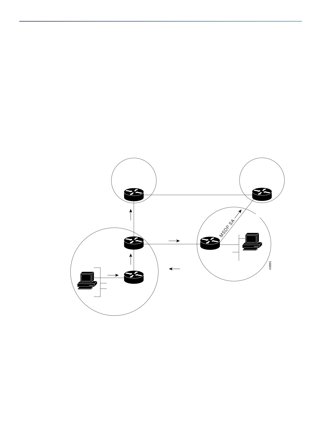
Figure 94 on page 774 shows MSDP operating between two MSDP peers. PIM uses MSDP as the standard mechanism
to register a source with the RP of a domain. When MSDP is configured, this sequence occurs.
When a source sends its first multicast packet, the first-hop router (designated router or RP) directly connected to the
source sends a PIM register message to the RP. The RP uses the register message to register the active source and to
forward the multicast packet down the shared tree in the local domain. With MSDP configured, the RP also forwards a
source-active (SA) message to all MSDP peers. The SA message identifies the source, the group the source is sending
to, and the address of the RP or the originator ID (the IP address of the interface used as the RP address), if configured.
Each MSDP peer receives and forwards the SA message away from the originating RP to achieve peer reverse-path
flooding (RPF). The MSDP device examines the BGP or MBGP routing table to discover which peer is the next hop toward
the originating RP of the SA message. Such a peer is called an RPF peer (reverse-path forwarding peer). The MSDP
device forwards the message to all MSDP peers other than the RPF peer. For information on how to configure an MSDP
peer when BGP and MBGP are not supported, see Configuring a Default MSDP Peer, page 776.
Figure 94
MSDP Running Between RP Peers
RP + MSDP peer
MSDP peer
MSDP SA
Peer RPF flooding
MSDP SA
TCP connection
BGP
MSDP peer
Receiver
Register
Multicast
(S,G) Join
PIM
Source
DR
PIM sparse-mode
domain
If the MSDP peer receives the same SA message from a non-RPF peer toward the originating RP, it drops the message.
Otherwise, it forwards the message to all its MSDP peers.
The RP for a domain receives the SA message from an MSDP peer. If the RP has any join requests for the group the SA
message describes and if the (*,G) entry exists with a nonempty outgoing interface list, the domain is interested in the
group, and the RP triggers an (S,G) join toward the source. After the (S,G) join reaches the source’s DR, a branch of the
source tree has been built from the source to the RP in the remote domain. Multicast traffic can now flow from the source
across the source tree to the RP and then down the shared tree in the remote domain to the receiver.
774
Configuring MSDP
Prerequisites
MSDP Benefits
MSDP has these benefits:
It breaks up the shared multicast distribution tree. You can make the shared tree local to your domain. Your local
members join the local tree, and join messages for the shared tree never need to leave your domain.
PIM sparse-mode domains can rely only on their own RPs, decreasing reliance on RPs in another domain. This
increases security because you can prevent your sources from being known outside your domain.
Domains with only receivers can receive data without globally advertising group membership.
Global source multicast routing table state is not required, saving memory.
Prerequisites
The switch is running the IP services image.
You have enabled IP multicast routing and configured PIM for the networks where you want to configure MSDP.
Guidelines and Limitations
MSDP is not fully supported in this software release because of a lack of support for Multicast Border Gateway Protocol
(MBGP), which works closely with MSDP. However, it is possible to create default peers that MSDP can operate with if
MBGP is not running.
Default Settings
MSDP is not enabled, and no default MSDP peer exists.
Configuring MSDP
This section includes the following topics:
Configuring a Default MSDP Peer, page 776 (required)
Caching Source-Active State, page 778 (optional)
Requesting Source Information from an MSDP Peer, page 780 (optional)
Controlling Source Information that Your Switch Originates, page 780 (optional)
Controlling Source Information that Your Switch Forwards, page 784 (optional)
Controlling Source Information that Your Switch Receives, page 786 (optional)
Configuring an MSDP Mesh Group, page 789 (optional)
Shutting Down an MSDP Peer, page 790 (optional)
Including a Bordering PIM Dense-Mode Region in MSDP, page 790 (optional)
Configuring an Originating Address other than the RP Address, page 791 (optional)
775

Configuring MSDP
Configuring MSDP
Configuring a Default MSDP Peer
In this software release, because BGP and MBGP are not supported, you cannot configure an MSDP peer on the local
switch by using the ip msdp peer global configuration command. Instead, you define a default MSDP peer (by using the
ip msdp default-peer global configuration command) from which to accept all SA messages for the switch. The default
MSDP peer must be a previously configured MSDP peer. Configure a default MSDP peer when the switch is not BGP- or
MBGP-peering with an MSDP peer. If a single MSDP peer is configured, the switch always accepts all SA messages from
that peer.
Figure 95 on page 776 shows a network in which default MSDP peers might be used. In Figure 95 on page 776, a
customer who owns Switch B is connected to the Internet through two Internet service providers (ISPs), one owning
Router A and the other owning Router C. They are not running BGP or MBGP between them. To learn about sources in
the ISP’s domain or in other domains, Switch B at the customer site identifies Router A as its default MSDP peer. Switch
B advertises SA messages to both Router A and Router C but accepts SA messages only from Router A or only from
Router C. If Router A is first in the configuration file, it is used if it is running. If Router A is not running, only then does
Switch B accept SA messages from Router C. This is the default behavior without a prefix list.
If you specify a prefix list, the peer is a default peer only for the prefixes in the list. You can have multiple active default
peers when you have a prefix list associated with each. When you do not have any prefix lists, you can configure multiple
default peers, but only the first one is the active default peer as long as the router has connectivity to this peer and the
peer is alive. If the first configured peer fails or the connectivity to this peer fails, the second configured peer becomes
the active default, and so on.
The ISP probably uses a prefix list to define which prefixes it accepts from the customer’s router.
Figure 95
Default MSDP Peer Network
Router C
Default MSDP peer
ISP C PIM domain
SA
10.1.1.1
SA
SA
Router A
Switch B
Default MSDP peer
Default MSDP peer
ISP A PIM domain
Customer PIM domain
Follow this procedure to specify a default MSDP peer. This procedure is required.
BEFORE YOU BEGIN
An MSDP default peer must be a previously configured MSDP peer. Before configuring a default MSDP peer, you must
first configure an MSDP peer.
776

Configuring MSDP
Configuring MSDP
DETAILED STEPS
Table 0-1
Command
Purpose
1.
configure terminal
Enter global configuration mode.
2.
ip msdp default-peer ip-address |
Define a default peer from which to accept all MSDP SA
name [prefix-list list]
messages.
For ip-address | name, enter the IP address or Domain
Name System (DNS) server name of the MSDP default
peer.
(Optional) For prefix-list list, enter the list name that
specifies the peer to be the default peer only for the listed
prefixes. You can have multiple active default peers when
you have a prefix list associated with each.
When you enter multiple ip msdp default-peer
commands with the prefix-list keyword, you use all the
default peers at the same time for different RP prefixes.
This syntax is typically used in a service provider cloud that
connects stub site clouds.
When you enter multiple ip msdp default-peer
commands without the prefix-list keyword, a single active
peer accepts all SA messages. If that peer fails, the next
configured default peer accepts all SA messages. This
syntax is typically used at a stub site.
3.
ip prefix-list name [description
(Optional) Create a prefix list using the name specified in Step
string] | seq number {permit | deny}
2.
network length
(Optional) For description string, enter a description of up
to 80 characters to describe this prefix list.
For seq number, enter the sequence number of the entry.
The range is 1 to 4294967294.
The deny keyword denies access to matching conditions.
The permit keyword permits access to matching
conditions.
For network length, specify the network number and
length (in bits) of the network mask that is permitted or
denied.
4.
ip msdp description {peer-name |
(Optional) Configure a description for the specified peer to
peer-address} text
make it easier to identify in a configuration or in show
command output.
By default, no description is associated with an MSDP peer.
5.
end
Return to privileged EXEC mode.
6.
show running-config
Verify your entries.
7.
copy running-config
(Optional) Save your entries in the configuration file.
startup-config
777
Configuring MSDP
Configuring MSDP
To remove the default peer, use the no ip msdp default-peer ip-address | name global configuration command.
EXAMPLE
This example shows a partial configuration of Router A and Router C in Figure 95 on page 776. Each of these ISPs have
more than one customer (like the customer in Figure 95 on page 776) who use default peering (no BGP or MBGP). In that
case, they might have similar configurations. That is, they accept SAs only from a default peer if the SA is permitted by
the corresponding prefix list.
Router A
Router(config)# ip msdp default-peer 10.1.1.1
Router(config)# ip msdp default-peer 10.1.1.1 prefix-list site-a
Router(config)# ip prefix-list site-b permit 10.0.0.0/1
Router C
Router(config)# ip msdp default-peer 10.1.1.1 prefix-list site-a
Router(config)# ip prefix-list site-b permit 10.0.0.0/1
Caching Source-Active State
By default, the switch does not cache source/group pairs from received SA messages. When the switch forwards the
MSDP SA information, it does not store it in memory. Therefore, if a member joins a group soon after a SA message is
received by the local RP, that member needs to wait until the next SA message to hear about the source. This delay is
known as join latency.
If you want to sacrifice some memory in exchange for reducing the latency of the source information, you can configure
the switch to cache SA messages. This procedure is optional.
Note: An alternative to this command is the ip msdp sa-request global configuration command, which causes the switch
to send an SA request message to the MSDP peer when a new member for a group becomes active. For more
information, see the next section.
778

Configuring MSDP
Configuring MSDP
DETAILED STEPS
Table 0-2
Command
Purpose
1.
configure terminal
Enter global configuration mode.
2.
ip msdp cache-sa-state [list
Enable the caching of source/group pairs (create an SA state).
access-list-number]
Those pairs that pass the access list are cached.
For list access-list-number, the range is 100 to 199.
3.
access-list access-list-number
Create an IP extended access list, repeating the command as
{deny | permit} protocol source
many times as necessary.
source-wildcard destination
destination-wildcard
For access-list-number, the range is 100 to 199. Enter the
same number created in Step 2.
The deny keyword denies access if the conditions are
matched. The permit keyword permits access if the
conditions are matched.
For protocol, enter ip as the protocol name.
For source, enter the number of the network or host from
which the packet is being sent.
For source-wildcard, enter the wildcard bits in dotted
decimal notation to be applied to the source. Place ones in
the bit positions that you want to ignore.
For destination, enter the number of the network or host to
which the packet is being sent.
For destination-wildcard, enter the wildcard bits in dotted
decimal notation to be applied to the destination. Place
ones in the bit positions that you want to ignore.
Recall that the access list is always terminated by an implicit
deny statement for everything.
4.
end
Return to privileged EXEC mode.
5.
show running-config
Verify your entries.
6.
copy running-config
(Optional) Save your entries in the configuration file.
startup-config
To return to the default setting (no SA state is created), use the no ip msdp cache-sa-state global configuration
command.
EXAMPLE
This example shows how to enable the cache state for all sources in 171.69.0.0/16 sending to groups 224.2.0.0/16:
Switch(config)# ip msdp cache-sa-state 100
Switch(config)# access-list 100 permit ip 171.69.0.0 0.0.255.255 224.2.0.0 0.0.255.255
779

Configuring MSDP
Configuring MSDP
Requesting Source Information from an MSDP Peer
Local RPs can send SA requests and get immediate responses for all active sources for a given group. By default, the
switch does not send any SA request messages to its MSDP peers when a new member joins a group and wants to
receive multicast traffic. The new member waits to receive the next periodic SA message.
If you want a new member of a group to learn the active multicast sources in a connected PIM sparse-mode domain that
are sending to a group, configure the switch to send SA request messages to the specified MSDP peer when a new
member joins a group. The peer replies with the information in its SA cache. If the peer does not have a cache configured,
this command has no result. Configuring this feature reduces join latency but sacrifices memory.
Follow this procedure to configure the switch to send SA request messages to the MSDP peer when a new member joins
a group and wants to receive multicast traffic. This procedure is optional.
DETAILED STEPS
Table 0-3
Command
Purpose
1.
configure terminal
Enter global configuration mode.
2.
ip msdp sa-request {ip-address |
Configure the switch to send SA request messages to the
name}
specified MSDP peer.
For ip-address | name, enter the IP address or name of the
MSDP peer from which the local switch requests SA messages
when a new member for a group becomes active.
Repeat the command for each MSDP peer that you want to
supply with SA messages.
3.
end
Return to privileged EXEC mode.
4.
show running-config
Verify your entries.
5.
copy running-config
(Optional) Save your entries in the configuration file.
startup-config
To return to the default setting, use the no ip msdp sa-request {ip-address | name} global configuration command.
EXAMPLE
This example shows how to configure the switch to send SA request messages to the MSDP peer at 171.69.1.1:
Switch(config)# ip msdp sa-request 171.69.1.1
Controlling Source Information that Your Switch Originates
You can control the multicast source information that originates with your switch:
Sources you advertise (based on your sources)
Receivers of source information (based on knowing the requestor)
For more information, see Redistributing Sources, page 780 and Filtering Source-Active Request Messages, page 782.
Redistributing Sources
SA messages originate on RPs to which sources have registered. By default, any source that registers with an RP is
advertised. The A flag is set in the RP when a source is registered, which means the source is advertised in an SA unless
it is filtered. Follow this procedure to further restrict which registered sources are advertised. This procedure is optional.
780

Configuring MSDP
Configuring MSDP
BEFORE YOU BEGIN
For best practice information related to configuring MSDP SA message filters, see the Multicast Source Discovery
Protocol SA Filter Recommendations tech note.
DETAILED STEPS
Command
Purpose
1.
configure terminal
Enter global configuration mode.
2.
ip msdp redistribute [list
Configure which (S,G) entries from the multicast routing table
access-list-name] [asn
are advertised in SA messages.
aspath-access-list-number]
[route-map map]
By default, only sources within the local domain are advertised.
(Optional) For list access-list-name, enter the name or
number of an IP standard or extended access list. The
range is 1 to 99 for standard access lists and 100 to 199
for extended lists. The access list controls which local
sources are advertised and to which groups they send.
(Optional) For asn aspath-access-list-number, enter the
IP standard or extended access list number in the range 1
to 199. This access list number must also be configured in
the ip as-path access-list command.
(Optional) For route-map map, enter the IP standard or
extended access list number in the range 1 to 199. This
access list number must also be configured in the ip
as-path access-list command.
The switch advertises (S,G) pairs according to the access list
or autonomous system path access list.
781

Configuring MSDP
Configuring MSDP
Command
Purpose
3.
access-list access-list-number
Create an IP standard access list, repeating the command as
{deny | permit} source
many times as necessary.
[source-wildcard]
or
or
Create an IP extended access list, repeating the command as
access-list access-list-number
many times as necessary.
{deny | permit} protocol source
source-wildcard destination
For access-list-number, the range is 1 to 99 for standard
destination-wildcard
access lists and 100 to 199 for extended lists. Enter the
same number created in Step 2.
The deny keyword denies access if the conditions are
matched. The permit keyword permits access if the
conditions are matched.
For protocol, enter ip as the protocol name.
For source, enter the number of the network or host from
which the packet is being sent.
For source-wildcard, enter the wildcard bits in dotted
decimal notation to be applied to the source. Place ones in
the bit positions that you want to ignore.
For destination, enter the number of the network or host to
which the packet is being sent.
For destination-wildcard, enter the wildcard bits in dotted
decimal notation to be applied to the destination. Place
ones in the bit positions that you want to ignore.
Recall that the access list is always terminated by an implicit
deny statement for everything.
4.
end
Return to privileged EXEC mode.
5.
show running-config
Verify your entries.
6.
copy running-config
(Optional) Save your entries in the configuration file.
startup-config
To remove the filter, use the no ip msdp redistribute global configuration command.
EXAMPLE
The following example shows how to configure which (S, G) entries from the mroute table are advertised in SA messages
originated from AS 64512:
Switch(config)# ip msdp redistribute route-map customer-sources
Switch(config)# route-map customer-sources permit
Switch(config)# match as-path 100
Switch(config)# ip as-path access-list 100 permit ^64512$
Filtering Source-Active Request Messages
By default, only switches that are caching SA information can respond to SA requests. By default, such a switch honors
all SA request messages from its MSDP peers and supplies the IP addresses of the active sources.
782

Configuring MSDP
Configuring MSDP
However, you can configure the switch to ignore all SA requests from an MSDP peer. You can also honor only those SA
request messages from a peer for groups described by a standard access list. If the groups in the access list pass, SA
request messages are accepted. All other such messages from the peer for other groups are ignored.
Follow this procedure to configure one of these options. This procedure is optional.
DETAILED STEPS
Table 0-4
Command
Purpose
1.
configure terminal
Enter global configuration mode.
2.
ip msdp filter-sa-request
Filter all SA request messages from the specified MSDP peer.
ip-address | name
or
or
Filter SA request messages from the specified MSDP peer for
ip msdp filter-sa-request
groups that pass the standard access list. The access list
{ip-address | name} list
describes a multicast group address. The range for the
access-list-number
access-list-number is 1 to 99.
3.
access-list access-list-number
Create an IP standard access list, repeating the command as
{deny | permit} source
many times as necessary.
[source-wildcard]
For access-list-number, the range is 1 to 99.
The deny keyword denies access if the conditions are
matched. The permit keyword permits access if the
conditions are matched.
For source, enter the number of the network or host from
which the packet is being sent.
(Optional) For source-wildcard, enter the wildcard bits in
dotted decimal notation to be applied to the source. Place
ones in the bit positions that you want to ignore.
Recall that the access list is always terminated by an implicit
deny statement for everything.
4.
end
Return to privileged EXEC mode.
5.
show running-config
Verify your entries.
6.
copy running-config
(Optional) Save your entries in the configuration file.
startup-config
To return to the default setting, use the no ip msdp filter-sa-request {ip-address | name} global configuration command.
EXAMPLE
This example shows how to configure the switch to filter SA request messages from the MSDP peer at 171.69.2.2. SA
request messages from sources on network 192.4.22.0 pass access list 1 and are accepted; all others are ignored.
Switch(config)# ip msdp filter sa-request 171.69.2.2 list 1
Switch(config)# access-list 1 permit 192.4.22.0 0.0.0.255
783
Configuring MSDP
Configuring MSDP
Controlling Source Information that Your Switch Forwards
By default, the switch forwards all SA messages it receives to all its MSDP peers. However, you can prevent outgoing
messages from being forwarded to a peer by using a filter or by setting a time-to-live (TTL) value. These methods are
described in the next sections.
Using a Filter
By creating a filter, you can perform one of these actions:
Filter all source/group pairs
Specify an IP extended access list to pass only certain source/group pairs
Filter based on match criteria in a route map
Follow this procedure to apply a filter. This procedure is optional.
BEFORE YOU BEGIN
For best practice information related to configuring MSDP SA message filters, see the Multicast Source Discovery
Protocol SA Filter Recommendations tech note.
784

Configuring MSDP
Configuring MSDP
DETAILED STEPS
Table 0-5
Command
Purpose
1.
configure terminal
Enter global configuration mode.
2.
ip msdp sa-filter out ip-address |
Filter all SA messages to the specified MSDP peer.
name
or
or
To the specified peer, pass only those SA messages that pass
ip msdp sa-filter out {ip-address |
the IP extended access list. The range for the extended
name} list access-list-number
access-list-number is 100 to 199.
If both the list and the route-map keywords are used, all
conditions must be true to pass any (S,G) pair in outgoing SA
messages.
or
or
ip msdp sa-filter out {ip-address |
To the specified MSDP peer, pass only those SA messages that
name} route-map map-tag
meet the match criteria in the route map map-tag.
If all match criteria are true, a permit from the route map
passes routes through the filter. A deny filters routes.
3.
access-list access-list-number
(Optional) Create an IP extended access list, repeating the
{deny | permit} protocol source
command as many times as necessary.
source-wildcard destination
destination-wildcard
For access-list-number, enter the number specified in
Step 2.
The deny keyword denies access if the conditions are
matched. The permit keyword permits access if the
conditions are matched.
For protocol, enter ip as the protocol name.
For source, enter the number of the network or host from
which the packet is being sent.
For source-wildcard, enter the wildcard bits in dotted
decimal notation to be applied to the source. Place ones
in the bit positions that you want to ignore.
For destination, enter the number of the network or host to
which the packet is being sent.
For destination-wildcard, enter the wildcard bits in dotted
decimal notation to be applied to the destination. Place
ones in the bit positions that you want to ignore.
Recall that the access list is always terminated by an implicit
deny statement for everything.
4.
end
Return to privileged EXEC mode.
5.
show running-config
Verify your entries.
6.
copy running-config
(Optional) Save your entries in the configuration file.
startup-config
785

Configuring MSDP
Configuring MSDP
To remove the filter, use the no ip msdp sa-filter out {ip-address | name} [list access-list-number] [route-map
map-tag] global configuration command.
EXAMPLE
This example shows how to allow only (S,G) pairs that pass access list 100 to be forwarded in an SA message to the
peer named switch.cisco.com:
Switch(config)# ip msdp peer switch.cisco.com connect-source gigabitethernet0/1
Switch(config)# ip msdp sa-filter out switch.cisco.com list 100
Switch(config)# access-list 100 permit ip 171.69.0.0 0.0.255.255 224.20 0 0.0.255.255
Using TTL to Limit the Multicast Data Sent in SA Messages
You can use a TTL value to control what data is encapsulated in the first SA message for every source. Only multicast
packets with an IP-header TTL greater than or equal to the ttl argument are sent to the specified MSDP peer. For
example, you can limit internal traffic to a TTL of 8. If you want other groups to go to external locations, you must send
those packets with a TTL greater than 8.
Follow this procedure to establish a TTL threshold. This procedure is optional.
DETAILED STEPS
Table 0-6
Command
Purpose
1.
configure terminal
Enter global configuration mode.
2.
ip msdp ttl-threshold {ip-address |
Limit which multicast data is encapsulated in the first SA
name} ttl
message to the specified MSDP peer.
For ip-address | name, enter the IP address or name of the
MSDP peer to which the TTL limitation applies.
For ttl, enter the TTL value. The default is 0, which means
all multicast data packets are forwarded to the peer until
the TTL is exhausted. The range is 0 to 255.
3.
end
Return to privileged EXEC mode.
4.
show running-config
Verify your entries.
5.
copy running-config
(Optional) Save your entries in the configuration file.
startup-config
To return to the default setting, use the no ip msdp ttl-threshold {ip-address | name} global configuration command.
EXAMPLE
The following example shows how to configure a TTL threshold of 8 hops:
Switch(config)# ip msdp ttl-threshold 192.168.1.5 8
Controlling Source Information that Your Switch Receives
By default, the switch receives all SA messages that its MSDP RPF peers send to it. However, you can control the source
information that you receive from MSDP peers by filtering incoming SA messages. In other words, you can configure the
switch to not accept them.
You can perform one of these actions:
786