Cisco Industrial Ethernet 4000, 4010 and 5000 Switch Software. Configuration Guide (2022) - page 26

Configuring Static IP Unicast Routing
Configuring Static Unicast Routes
An IP address identifies a destination for IP packets. Some IP addresses are reserved for special uses and cannot be
used for host, subnet, or network addresses. RFC 1166, “Internet Numbers,” contains the official description of these IP
addresses.
An interface can have one primary IP address. A a subnet mask identifies the bits that denote the network number in an
IP address.
This task explains how to assign an IP address and a network mask to an SVI
Command
Purpose
1.
configure terminal
Enters global configuration mode.
2.
interface vlan vlan_id
Enters interface configuration mode, and specifies the Layer 3
VLAN to configure.
3.
ip address ip-address subnet-mask
Configures the IP address and IP subnet mask.
4.
end
Returns to privileged EXEC mode.
Configuring Static Unicast Routes
Static unicast routes are user-defined routes that cause packets moving between a source and a destination to take a
specified path. Static routes can be important if the router cannot build a route to a particular destination and are useful
for specifying a gateway of last resort to which all unroutable packets are sent.
Use the no ip route prefix mask {address | interface} global configuration command to remove a static route. The switch
retains static routes until you remove them.
When an interface goes down, all static routes through that interface are removed from the IP routing table. When the
software can no longer find a valid next hop for the address specified as the forwarding router's address in a static route,
the static route is also removed from the IP routing table.
Command
Purpose
1.
configure terminal
Enters global configuration mode.
2.
ip route prefix mask {address | interface} [distance]
Establishs a static route.
3.
end
Returns to privileged EXEC mode.
Monitoring and Maintaining the IP Network
Command
Description
show interfaces [interface-id]
Displays the administrative and operational status of all interface
specified interface.
Additional References for Configuring IP Unicast Routing
The following sections provide references related to switch administration:
697

Configuring Static IP Unicast Routing
Additional References for Configuring IP Unicast Routing
Related Documents
Related Topic
Document Title
Cisco IOS basic commands
Cisco IOS Configuration Fundamentals Command Reference
Cisco IOS IP address commands
Cisco IOS IP Command Reference, Volume 1 of 3: Addressing and
Services, Release 15.0
Cisco IP routing configuration
Cisco IOS IP Routing Configuration Guides, Release 15.0
SDM template configuration
Configuring SDM Templates, page 137
Standards
Standards
Title
No new or modified standards are supported by this
—
feature, and support for existing standards has not
been modified by this feature.
MIBs
MIBs
MIBs Link
—
To locate and download MIBs using Cisco IOS XR software, use the
Cisco MIB Locator found at the following URL and choose a platform
under the Cisco Access Products menu:
RFCs
RFCs
Title
No new or modified RFCs are supported by this
—
feature, and support for existing RFCs has not been
modified by this feature.
Technical Assistance
Description
Link
The Cisco Technical Support website contains
thousands of pages of searchable technical content,
including links to products, technologies, solutions,
technical tips, and tools. Registered Cisco.com users
can log in from this page to access even more content.
698
Configuring IPv6 Host Functions
This chapter describes how to configure IPv6 host functions on the switch.
Prerequisites Configuring IPv6 Host Functions
To enable dual-stack environments (supporting both IPv4 and IPv6), you must configure the switch to use the a dual
IPv4 and IPv6 switch database management (SDM) template. See Dual IPv4 and IPv6 Protocol Stacks, page 702.
Information About Configuring IPv6 Host Functions
IPv6
IPv4 users can move to IPv6 and receive services such as end-to-end security, quality of service (QoS), and globally
unique addresses. The IPv6 address space reduces the need for private addresses and Network Address Translation
(NAT) processing by border routers at network edges.
For information about how Cisco Systems implements IPv6, go to this URL:
For information about IPv6 and other features in this chapter
See the Cisco IOS IPv6 Configuration Library at this URL:
This section describes IPv6 implementation on the switch. These sections are included:
IPv6 Addresses, page 699
Supported IPv6 Host Features, page 700
How to Configure IPv6 Hosting, page 704
IPv6 Addresses
The switch supports only IPv6 unicast addresses. It does not support site-local unicast addresses, anycast addresses,
or multicast addresses.
The IPv6 128-bit addresses are represented as a series of eight 16-bit hexadecimal fields separated by colons in the
format: n:n:n:n:n:n:n:n. This is an example of an IPv6 address:
2031:0000:130F:0000:0000:09C0:080F:130B
For easier implementation, leading zeros in each field are optional. This is the same address without leading zeros:
2031:0:130F:0:0:9C0:80F:130B
699
Configuring IPv6 Host Functions
Information About Configuring IPv6 Host Functions
You can also use two colons (::) to represent successive hexadecimal fields of zeros, but you can use this short version
only once in each address:
2031:0:130F::09C0:080F:130B
For more information about IPv6 address formats, address types, and the IPv6 packet header, see the “Implementing
IPv6 Addressing and Basic Connectivity” chapter of Cisco IOS IPv6 Configuration Library on Cisco.com.
In the “Implementing Addressing and Basic Connectivity” chapter, these sections apply to the switch:
IPv6 Address Formats
IPv6 Address Output Display
Simplified IPv6 Packet Header
Supported IPv6 Host Features
These sections describe the IPv6 protocol features supported by the switch:
128-Bit Wide Unicast Addresses, page 700
DNS for IPv6, page 701
ICMPv6, page 701
Neighbor Discovery, page 701
Default Router Preference, page 701
IPv6 Stateless Autoconfiguration and Duplicate Address Detection, page 701
IPv6 Applications, page 702
Dual IPv4 and IPv6 Protocol Stacks, page 702
SNMP and Syslog Over IPv6, page 703
HTTP over IPv6, page 703
Support on the switch includes expanded address capability, header format simplification, improved support of
extensions and options, and hardware parsing of the extension header. The switch supports hop-by-hop extension
header packets, which are routed or bridged in software.
128-Bit Wide Unicast Addresses
The switch supports aggregatable global unicast addresses and link-local unicast addresses. It does not support
site-local unicast addresses.
Aggregatable global unicast addresses are IPv6 addresses from the aggregatable global unicast prefix. The address
structure enables strict aggregation of routing prefixes and limits the number of routing table entries in the global
routing table. These addresses are used on links that are aggregated through organizations and eventually to the
Internet service provider.
These addresses are defined by a global routing prefix, a subnet ID, and an interface ID. Current global unicast
address allocation uses the range of addresses that start with binary value 001 (2000::/3). Addresses with a prefix
of 2000::/3(001) through E000::/3(111) must have 64-bit interface identifiers in the extended unique identifier
(EUI)-64 format.
700
Configuring IPv6 Host Functions
Information About Configuring IPv6 Host Functions
Link local unicast addresses can be automatically configured on any interface by using the link-local prefix
FE80::/10(1111 1110 10) and the interface identifier in the modified EUI format. Link-local addresses are used in the
neighbor discovery protocol (NDP) and the stateless autoconfiguration process. Nodes on a local link use link-local
addresses and do not require globally unique addresses to communicate. IPv6 routers do not forward packets with
link-local source or destination addresses to other links.
For more information, see the section about IPv6 unicast addresses in the “Implementing IPv6 Addressing and Basic
Connectivity” chapter in the Cisco IOS IPv6 Configuration Library on Cisco.com.
DNS for IPv6
IPv6 supports Domain Name System (DNS) record types in the DNS name-to-address and address-to-name lookup
processes. The DNS AAAA resource record types support IPv6 addresses and are equivalent to an A address record in
IPv4. The switch supports DNS resolution for IPv4 and IPv6.
ICMPv6
The Internet Control Message Protocol (ICMP) in IPv6 generates error messages, such as ICMP destination unreachable
messages, to report errors during processing and other diagnostic functions. In IPv6, ICMP packets are also used in the
neighbor discovery protocol and path MTU discovery.
Neighbor Discovery
The switch supports NDP for IPv6, a protocol running on top of ICMPv6, and static neighbor entries for IPv6 stations that
do not support NDP. The IPv6 neighbor discovery process uses ICMP messages and solicited-node multicast addresses
to determine the link-layer address of a neighbor on the same network (local link), to verify the reachability of the
neighbor, and to keep track of neighboring routers.
The switch supports ICMPv6 redirect for routes with mask lengths less than 64 bits. ICMP redirect is not supported for
host routes or for summarized routes with mask lengths greater than 64 bits.
Neighbor discovery throttling ensures that the switch CPU is not unnecessarily burdened while it is in the process of
obtaining the next hop forwarding information to route an IPv6 packet. The switch drops any additional IPv6 packets
whose next hop is the same neighbor that the switch is actively trying to resolve. This drop avoids further load on the
CPU.
Default Router Preference
The switch supports IPv6 default router preference (DRP), an extension in router advertisement messages. DRP improves
the ability of a host to select an appropriate router, especially when the host is multihomed and the routers are on different
links. The switch does not support the Route Information Option in RFC 4191.
An IPv6 host maintains a default router list from which it selects a router for traffic to offlink destinations. The selected
router for a destination is then cached in the destination cache. NDP for IPv6 specifies that routers that are reachable or
probably reachable are preferred over routers whose reachability is unknown or suspect. For reachable or probably
reachable routers, NDP can either select the same router every time or cycle through the router list. By using DRP, you
can configure an IPv6 host to prefer one router over another, provided both are reachable or probably reachable.
For more information about DRP for IPv6, see the “Implementing IPv6 Addresses and Basic Connectivity” chapter in the
Cisco IOS IPv6 Configuration Library on Cisco.com.
IPv6 Stateless Autoconfiguration and Duplicate Address Detection
The switch uses stateless autoconfiguration to manage link, subnet, and site addressing changes, such as management
of host and mobile IP addresses. A host autonomously configures its own link-local address, and booting nodes send
router solicitations to request router advertisements for configuring interfaces.
701
Configuring IPv6 Host Functions
Information About Configuring IPv6 Host Functions
For more information about autoconfiguration and duplicate address detection, see the “Implementing IPv6 Addressing
and Basic Connectivity” chapter of Cisco IOS IPv6 Configuration Library on Cisco.com.
IPv6 Applications
The switch has IPv6 support for these applications:
Ping, traceroute, Telnet, TFTP, and FTP
Secure Shell (SSH) over an IPv6 transport
HTTP server access over IPv6 transport
DNS resolver for AAAA over IPv4 transport
Cisco Discovery Protocol (CDP) support for IPv6 addresses
For more information about managing these applications, see the “Managing Cisco IOS Applications over IPv6” chapter
and the “Implementing IPv6 Addressing and Basic Connectivity” chapter in the Cisco IOS IPv6 Configuration Library on
Cisco.com.
Dual IPv4 and IPv6 Protocol Stacks
You must use the dual IPv4 and IPv6 template to allocate ternary content addressable memory (TCAM) usage to both
IPv4 and IPv6 protocols.
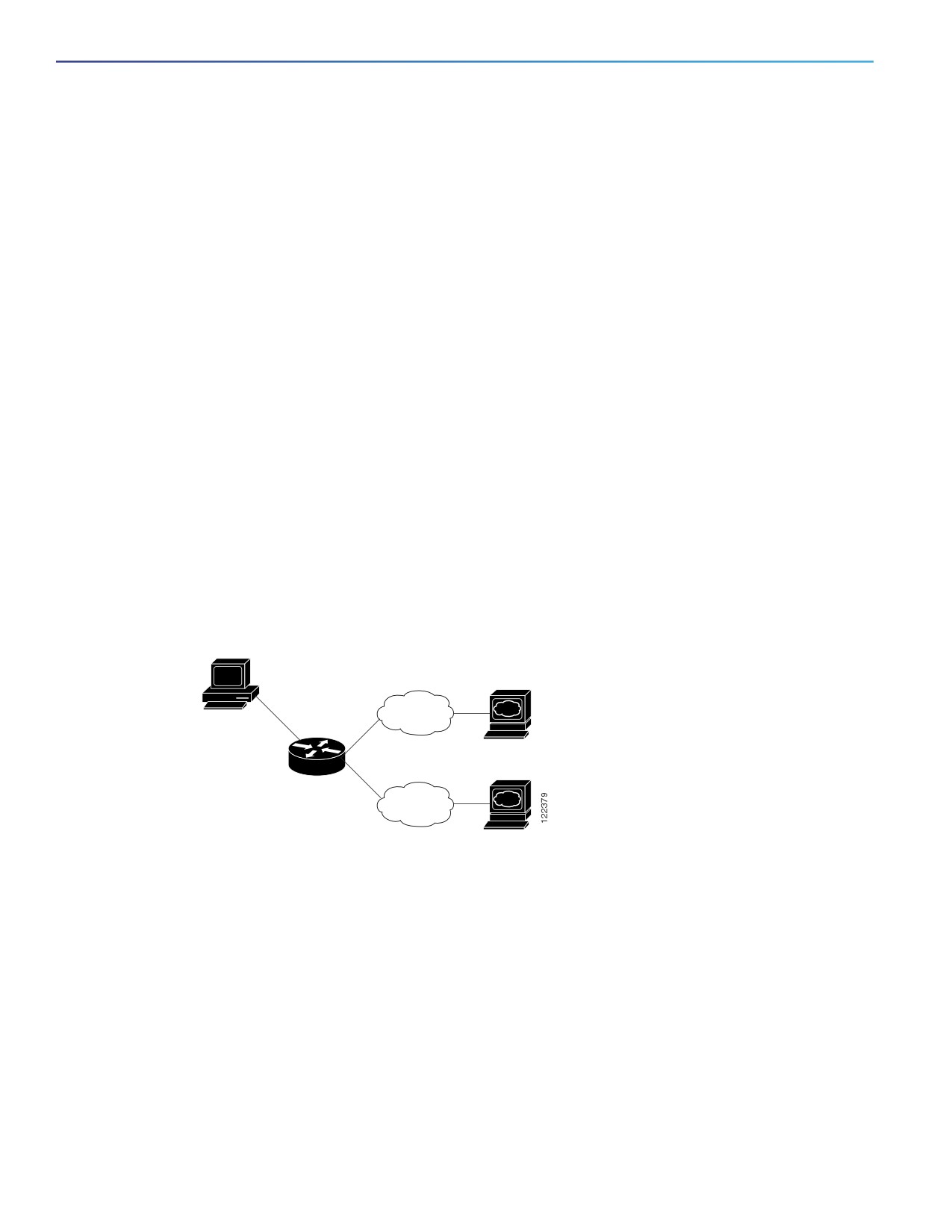
Figure 86 shows a router forwarding both IPv4 and IPv6 traffic through the same interface, based on the IP packet and
destination addresses.
Figure 86
Dual IPv4 and IPv6 Support on an Interface
IPv4
10.1.1.1
IPv6
3ffe:yyyy::1
Use the dual IPv4 and IPv6 switch database management (SDM) template to enable dual-stack environments (supporting
both IPv4 and IPv6).
The dual IPv4 and IPv6 templates allow the switch to be used in dual-stack environments.
If you try to configure IPv6 without first selecting a dual IPv4 and IPv6 template, a warning message appears.
In IPv4-only environments, the switch applies IPv4 QoS and ACLs in hardware. IPv6 packets are not supported.
In dual IPv4 and IPv6 environments, the switch applies IPv4 QoS and ACLs in hardware.
IPv6 QoS and ACLs are not supported.
If you do not plan to use IPv6, do not use the dual-stack template because this template results in less TCAM
capacity for each resource.
For more information about IPv4 and IPv6 protocol stacks, see the “Implementing IPv6 Addressing and Basic
Connectivity” chapter of Cisco IOS IPv6 Configuration Library on Cisco.com.
702
Configuring IPv6 Host Functions
Information About Configuring IPv6 Host Functions
Static Routes for IPv6
Static routes are manually configured and define an explicit route between two networking devices. Static routes are
useful for smaller networks with only one path to an outside network or to provide security for certain types of traffic in
a larger network.
For more information about static routes, see the “Implementing Static Routes for IPv6” chapter in the Cisco IOS IPv6
Configuration Library on Cisco.com.
SNMP and Syslog Over IPv6
To support both IPv4 and IPv6, IPv6 network management requires both IPv6 and IPv4 transports. Syslog over IPv6
supports address data types for these transports.
SNMP and syslog over IPv6 provide these features:
Support for both IPv4 and IPv6
IPv6 transport for SNMP and to modify the SNMP agent to support traps for an IPv6 host
SNMP- and syslog-related MIBs to support IPv6 addressing
Configuration of IPv6 hosts as trap receivers
For support over IPv6, SNMP modifies the existing IP transport mapping to simultaneously support IPv4 and IPv6. These
SNMP actions support IPv6 transport management:
Opens User Datagram Protocol (UDP) SNMP socket with default settings
Provides a new transport mechanism called SR_IPV6_TRANSPORT
Sends SNMP notifications over IPv6 transport
Supports SNMP-named access lists for IPv6 transport
Supports SNMP proxy forwarding using IPv6 transport
Verifies SNMP Manager feature works with IPv6 transport
For information on SNMP over IPv6, including configuration procedures, see the “Managing Cisco IOS Applications over
IPv6” chapter in the Cisco IOS IPv6 Configuration Library on Cisco.com.
For information about syslog over IPv6, including configuration procedures, see the “Implementing IPv6 Addressing and
Basic Connectivity” chapter in the Cisco IOS IPv6 Configuration Library on Cisco.com.
HTTP over IPv6
The HTTP client sends requests to both IPv4 and IPv6 HTTP servers, which respond to requests from both IPv4 and IPv6
HTTP clients. URLs with literal IPv6 addresses must be specified in hexadecimal using 16-bit values between colons.
The accept socket call chooses an IPv4 or IPv6 address family. The accept socket is either an IPv4 or IPv6 socket. The
listening socket continues to listen for both IPv4 and IPv6 signals that indicate a connection. The IPv6 listening socket is
bound to an IPv6 wildcard address.
The underlying TCP/IP stack supports a dual-stack environment. HTTP relies on the TCP/IP stack and the sockets for
processing network-layer interactions.
Basic network connectivity (ping) must exist between the client and the server hosts before HTTP connections can be
made.
703

Configuring IPv6 Host Functions
How to Configure IPv6 Hosting
Default IPv6 Settings
Feature
Default Setting
SDM template
Default.
IPv6 addresses
None configured.
How to Configure IPv6 Hosting
Configuring IPv6 Addressing and Enabling IPv6 Host
This section describes how to assign IPv6 addresses to individual Layer 3 interfaces and to globally forward IPv6 traffic
on the switch.
Before configuring IPv6 on the switch, consider these guidelines:
Be sure to select a dual IPv4 and IPv6 SDM template.
In the ipv6 address interface configuration command, you must enter the ipv6-address and ipv6-prefix variables
with the address specified in hexadecimal using 16-bit values between colons. The prefix-length variable (preceded
by a slash [/]) is a decimal value that shows how many of the high-order contiguous bits of the address comprise
the prefix (the network portion of the address).
To forward IPv6 traffic on an interface, you must configure a global IPv6 address on that interface. Configuring an IPv6
address on an interface automatically configures a link-local address and activates IPv6 for the interface. The configured
interface automatically joins these required multicast groups for that link:
solicited-node multicast group FF02:0:0:0:0:1:ff00::/104 for each unicast address assigned to the interface (this
address is used in the neighbor discovery process.)
all-nodes link-local multicast group FF02::1
all-routers link-local multicast group FF02::2
For more information about configuring IPv6, see the “Implementing Addressing and Basic Connectivity for IPv6” chapter
in the Cisco IOS IPv6 Configuration Library on Cisco.com.
Command
Purpose
1.
configure terminal
Enters global configuration mode.
2.
sdm prefer dual-ipv4-and-ipv6 default
Selects the SDM template that supports IPv4 and IPv6.
3.
end
Returns to privileged EXEC mode.
4.
reload
Reloads the operating system.
5.
configure terminal
Enters global configuration mode after the switch reloads.
6.
interface interface-id
Enters interface configuration mode, and specifies the interface
to configure.
704

Configuring IPv6 Host Functions
How to Configure IPv6 Hosting
Command
Purpose
7.
ipv6 address ipv6-prefix/prefix length eui-64
Specifies a global IPv6 address with an extended unique
identifier (EUI) in the low-order 64 bits of the IPv6 address.
Specifies only the network prefix; the last 64 bits are
automatically computed from the switch MAC address. This
enables IPv6 processing on the interface.
or
Specifies a link-local address on the interface to be used
ipv6 address ipv6-address link-local
instead of the link-local address that is automatically
configured when IPv6 is enabled on the interface. This
command enables IPv6 processing on the interface.
Automatically configures an IPv6 link-local address on the
or
interface, and enable the interface for IPv6 processing. The
link-local address can only be used to communicate with
ipv6 enable
nodes on the same link.
8.
exit
Returns to global configuration mode.
9.
end
Returns to privileged EXEC mode.
Configuring Default Router Preference
Router advertisement messages are sent with the default router preference (DRP) configured by the ipv6 nd
router-preference interface configuration command. If no DRP is configured, RAs are sent with a medium preference.
A DRP is useful when two routers on a link might provide equivalent, but not equal-cost routing, and policy might dictate
that hosts should prefer one of the routers.
Command
Purpose
1.
configure terminal
Enters global configuration mode.
2.
interface interface-id
Enters interface configuration mode, and enters the Layer 3 interface
on which you want to specify the DRP.
3.
ipv6 nd router-preference {high |
Specifies a DRP for the router on the switch interface.
medium | low}
4.
end
Returns to privileged EXEC mode.
Configuring IPv6 ICMP Rate Limiting
ICMP rate limiting is enabled by default with a default interval between error messages of 100 milliseconds and a bucket
size (maximum number of tokens to be stored in a bucket) of 10.
705

Configuring IPv6 Host Functions
Monitoring and Maintaining IPv6 Host Information
Command
Purpose
1.
configure terminal
Enters global configuration mode.
2.
ipv6 icmp error-interval interval [bucketsize]
Configures the interval and bucket size for IPv6 ICMP error
messages:
interval—The interval (in milliseconds) between tokens being
added to the bucket. The range is from 0 to 2147483647
milliseconds.
bucketsize—(Optional) The maximum number of tokens
stored in the bucket. The range is from 1 to 200.
3.
end
Returns to privileged EXEC mode.
Monitoring and Maintaining IPv6 Host Information
Command
Purpose
show ipv6 interface interface-id
Displays IPv6 interface status and configuration.
show ipv6 mtu
Displays IPv6 MTU per destination cache.
show ipv6 neighbors
Displays IPv6 neighbor cache entries.
show ipv6 prefix-list
Displays a list of IPv6 prefix lists.
show ipv6 protocols
Displays IPv6 routing protocols on the switch.
show ipv6 route
Displays the IPv6 route table entries.
show ipv6 static
Displays IPv6 static routes.
show ipv6 traffic
Displays IPv6 traffic statistics.
show ip http server history
Displays the previous 20 connections to the HTTP server, including
the IP address accessed and the time when the connection was
closed.
show ip http server connection
Displays the current connections to the HTTP server, including the
local and remote IP addresses being accessed.
show ip http client connection
Displays the configuration values for HTTP client connections to HTTP
servers.
show ip http client history
Displays a list of the last 20 requests made by the HTTP client to the
server.
Configuration Examples for IPv6 Host Functions
Enabling IPv6: Example
This example shows how to enable IPv6 with both a link-local address and a global address based on the IPv6 prefix
2001:0DB8:c18:1::/64. The EUI-64 interface ID is used in the low-order 64 bits of both addresses. Output from the show
ipv6 interface EXEC command shows how the interface ID (20B:46FF:FE2F:D940) is appended to the link-local prefix
FE80::/64 of the interface.
Switch(config)# sdm prefer dual-ipv4-and-ipv6 default
Switch(config)# interface gigabitethernetfastethernet1/0/11
Switch(config-if)# ipv6 address 2001:0DB8:c18:1::/64 eui 64
Switch(config-if)# end
706
Configuring IPv6 Host Functions
Configuration Examples for IPv6 Host Functions
Switch# show ipv6 interface gigabitethernetfastethernet1/0/11
GigabitEthernetFastEthernet1/0/11 is up, line protocol is up
IPv6 is enabled, link-local address is FE80::20B:46FF:FE2F:D940
Global unicast address(es):
2001:0DB8:c18:1:20B:46FF:FE2F:D940, subnet is 2001:0DB8:c18:1::/64 [EUI]
Joined group address(es):
FF02::1
FF02::2
FF02::1:FF2F:D940
MTU is 1500 bytes
ICMP error messages limited to one every 100 milliseconds
ICMP redirects are enabled
ND DAD is enabled, number of DAD attempts: 1
ND reachable time is 30000 milliseconds
ND advertised reachable time is 0 milliseconds
ND advertised retransmit interval is 0 milliseconds
ND router advertisements are sent every 200 seconds
ND router advertisements live for 1800 seconds
Hosts use stateless autoconfig for addresses.
Configuring DRP: Example
This example shows how to configure a DRP of high for the router on an interface.
Switch# configure terminal
Switch(config)# interface gigabitethernet1/0/1
Switch(config-if)# ipv6 nd router-preference high
Switch(config-if)# end
Configuring an IPv6 ICMP Error Message Interval
This example shows how to configure an IPv6 ICMP error message interval of 50 milliseconds and a bucket size of 20
tokens.
Switch(config)# ipv6 icmp error-interval 50 20
Displaying Show Command Output: Examples
This is an example of the output from the show ipv6 interface privileged EXEC command:
Switch# show ipv6 interface
Vlan1 is up, line protocol is up
IPv6 is enabled, link-local address is FE80::20B:46FF:FE2F:D940
Global unicast address(es):
3FFE:C000:0:1:20B:46FF:FE2F:D940, subnet is 3FFE:C000:0:1::/64 [EUI]
Joined group address(es):
FF02::1
FF02::2
FF02::1:FF2F:D940
MTU is 1500 bytes
ICMP error messages limited to one every 100 milliseconds
ICMP redirects are enabled
ND DAD is enabled, number of DAD attempts: 1
ND reachable time is 30000 milliseconds
ND advertised reachable time is 0 milliseconds
ND advertised retransmit interval is 0 milliseconds
ND router advertisements are sent every 200 seconds
707
Configuring IPv6 Host Functions
Configuration Examples for IPv6 Host Functions
ND router advertisements live for 1800 seconds
<output truncated>
This is an example of the output from the show ipv6 protocols privileged EXEC command:
Switch# show ipv6 protocols
IPv6 Routing Protocol is “connected”
IPv6 Routing Protocol is “static”
IPv6 Routing Protocol is “rip fer”
Interfaces:
Vlan6
FastEthernet0/4
FastEthernet0/11
FastEthernet0/12
GigabitEthernet2/0/4
GigabitEthernet2/0/
GigabitEthernet1/0/12
Redistribution:
None
This is an example of the output from the show ipv6 neighbor privileged EXEC command:
Switch# show ipv6 neighbors
IPv6 Address
Age Link-layer Addr State Interface
3FFE:C000:0:7::777
- 0007.0007.0007 REACH Vl7
3FFE:C101:113:1::33
- 0000.0000.0033 REACH Fa1/0/13
This is an example of the output from the show ipv6 route privileged EXEC command:
Switch# show ipv6 route
IPv6 Routing Table - Default - 1 entries
Codes: C - Connected, L - Local, S - Static, U - Per-user Static route
L
FF00::/8 [0/0]
via Null0, receive
This is an example of the output from the show ipv6 traffic privileged EXEC command.
Switch# show ipv6 traffic
IPv6 statistics:
Rcvd:
1 total, 1 local destination
0 source-routed, 0 truncated
0 format errors, 0 hop count exceeded
0 bad header, 0 unknown option, 0 bad source
0 unknown protocol, 0 not a router
0 fragments, 0 total reassembled
0 reassembly timeouts, 0 reassembly failures
Sent:
36861 generated, 0 forwarded
0 fragmented into 0 fragments, 0 failed
0 encapsulation failed, 0 no route, 0 too big
0 RPF drops, 0 RPF suppressed drops
Mcast: 1 received, 36861 sent
ICMP statistics:
Rcvd: 1 input, 0 checksum errors, 0 too short
0 unknown info type, 0 unknown error type
unreach: 0 routing, 0 admin, 0 neighbor, 0 address, 0 port
parameter: 0 error, 0 header, 0 option
0 hopcount expired, 0 reassembly timeout,0 too big
0 echo request, 0 echo reply
0 group query, 0 group report, 0 group reduce
1 router solicit, 0 router advert, 0 redirects
0 neighbor solicit, 0 neighbor advert
Sent: 10112 output, 0 rate-limited
unreach: 0 routing, 0 admin, 0 neighbor, 0 address, 0 port
parameter: 0 error, 0 header, 0 option
708
Configuring IPv6 Host Functions
Additional References
0 hopcount expired, 0 reassembly timeout,0 too big
0 echo request, 0 echo reply
0 group query, 0 group report, 0 group reduce
0 router solicit, 9944 router advert, 0 redirects
84 neighbor solicit, 84 neighbor advert
UDP statistics:
Rcvd: 0 input, 0 checksum errors, 0 length errors
0 no port, 0 dropped
Sent: 26749 output
TCP statistics:
Rcvd: 0 input, 0 checksum errors
Sent: 0 output, 0 retransmitted
Additional References
The following sections provide references related to switch administration:
709

Configuring IPv6 Host Functions
Additional References
Related Documents
Related Topic
Document Title
Cisco IOS basic commands
Cisco IOS Configuration Fundamentals Command Reference
Cisco IOS static IPv6 routing
“Implementing Static Routes for IPv6” chapter in the Cisco IOS IPv6
Configuration Library on Cisco.com.
DRP for IPv6
“Implementing IPv6 Addresses and Basic Connectivity” chapter in
the Cisco IOS IPv6 Configuration Library on Cisco.com
Standards
Standards
Title
No new or modified standards are supported by this
—
feature, and support for existing standards has not
been modified by this feature.
MIBs
MIBs
MIBs Link
—
To locate and download MIBs using Cisco IOS XR software, use the
Cisco MIB Locator found at the following URL and choose a platform
under the Cisco Access Products menu:
RFCs
RFCs
Title
No new or modified RFCs are supported by this
—
feature, and support for existing RFCs has not been
modified by this feature.
Technical Assistance
Description
Link
The Cisco Technical Support website contains
thousands of pages of searchable technical content,
including links to products, technologies, solutions,
technical tips, and tools. Registered Cisco.com users
can log in from this page to access even more content.
710
Configuring Link State Tracking
Restrictions for Configuring Link State Tracking
To use this feature, the switch must be running the LAN Base image.
An interface that is defined as an upstream interface cannot also be defined as a downstream interface in the same
or a different link state group. The reverse is also true.
An interface cannot be a member of more than one link state group.
You can configure only two link state groups per switch.
Information About Configuring Link State Tracking
Link State Tracking
Link state tracking, also known as trunk failover, is a feature that binds the link state of multiple interfaces. For example,
link state tracking provides redundancy in the network when used with server NIC adapter teaming. When the server
network adapters are configured in a primary or secondary relationship known as teaming, if the link is lost on the primary
interface, connectivity is transparently changed to the secondary interface.
Note: An interface can be an aggregation of ports (an EtherChannel), a single physical port in access or trunk mode, or
a routed port.
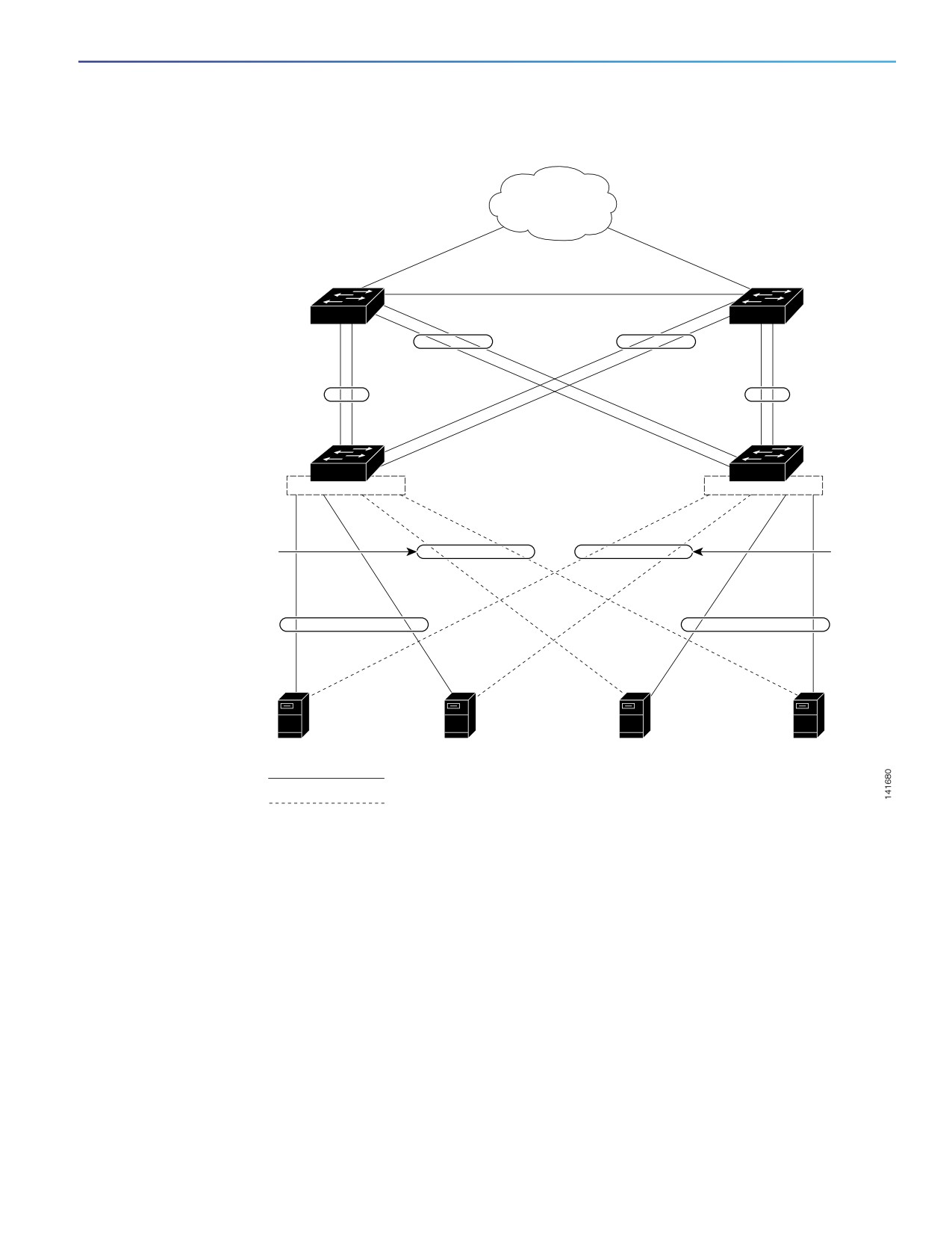
Figure 87 on page 713 shows a network configured with link state tracking. To enable link state tracking, create a link
state group, and specify the interfaces that are assigned to the link state group. In a link state group, these interfaces are
bundled together. The downstream interfaces are bound to the upstream interfaces. Interfaces connected to servers are
referred to as downstream interfaces, and interfaces connected to distribution switches and network devices are referred
to as upstream interfaces.
The configuration in Figure 87 on page 713 ensures that the network traffic flow is balanced as follows:
For links to switches and other network devices
— Server 1 and server 2 use switch A for primary links and switch B for secondary links.
— Server 3 and server 4 use switch B for primary links and switch A for secondary links.
Link state group 1 on switch A
— Switch A provides primary links to server 1 and server 2 through link state group 1. Port 1 is connected to
server 1, and port 2 is connected to server 2. Port 1 and port 2 are the downstream interfaces in link state group
1.
— Port 5 and port 6 are connected to distribution switch 1 through link state group 1. Port 5 and port 6 are the
upstream interfaces in link state group 1.
711
Configuring Link State Tracking
Link State Tracking
Link state group 2 on switch A
— Switch A provides secondary links to server 3 and server 4 through link state group 2. Port 3 is connected to
server 3, and port 4 is connected to server 4. Port 3 and port 4 are the downstream interfaces in link state group
2.
— Port 7 and port 8 are connected to distribution switch 2 through link state group 2. Port 7 and port 8 are the
upstream interfaces in link state group 2.
Link state group 2 on switch B
— Switch B provides primary links to server 3 and server 4 through link state group 2. Port 3 is connected to server
3, and port 4 is connected to server 4. Port 3 and port 4 are the downstream interfaces in link state group 2.
— Port 5 and port 6 are connected to distribution switch 2 through link state group 2. Port 5 and port 6 are the
upstream interfaces in link state group 2.
Link state group 1 on switch B
— Switch B provides secondary links to server 1 and server 2 through link state group 1. Port 1 is connected to
server 1, and port 2 is connected to server 2. Port 1 and port 2 are the downstream interfaces in link state group
1.
— Port 7 and port 8 are connected to distribution switch 1 through link state group 1. Port 7 and port 8 are the
upstream interfaces in link state group 1.
In a link state group, the upstream ports can become unavailable or lose connectivity because the distribution switch or
router fails, the cables are disconnected, or the link is lost. These are the interactions between the downstream and
upstream interfaces when link state tracking is enabled:
If any of the upstream interfaces are in the link-up state, the downstream interfaces can change to or remain in the
link-up state.
If all of the upstream interfaces become unavailable, link state tracking automatically puts the downstream interfaces
in the error-disabled state. Connectivity to and from the servers is automatically changed from the primary server
interface to the secondary server interface.
As an example of a connectivity change from link state group 1 to link state group 2 on switch A, see Figure 87 on
page 713. If the upstream link for port 6 is lost, the link states of downstream ports 1 and 2 do not change. However,
if the link for upstream port 5 is also lost, the link state of the downstream ports changes to the link-down state.
Connectivity to server 1 and server 2 is then changed from link state group1 to link state group 2. The downstream
ports 3 and 4 do not change state because they are in link-group 2.
If the link state group is configured, link state tracking is disabled, and the upstream interfaces lose connectivity, the
link states of the downstream interfaces remain unchanged. The server does not recognize that upstream
connectivity has been lost and does not failover to the secondary interface.
You can recover a downstream interface link-down condition by removing the failed downstream port from the link state
group. To recover multiple downstream interfaces, disable the link state group.
712
Configuring Link State Tracking
Link State Tracking
Figure 87
Typical Link State Tracking Configuration
Network
Layer 3 link
Distribution
Distribution
switch 1
switch 2
Link-state
Link-state
Link-state
group 1
group 2
Link-state
group 1
group 2
Port
Port
Port
Port
Port
Port
5
6
7
6
5
7
Port
Port
Switch A
Switch B
8
8
Port
Port Port Port
Port
Port
Port
Port
1
2
3
4
1
2
3
4
Link-
Link-
state
state
group 2
group 1
Link-
Link-
state
state
group 1
group 2
Server 1
Server 2
Server 3
Server 4
Primary link
Secondary link
Default Link State Tracking Configuration
There are no link state groups defined, and link state tracking is not enabled for any group.
713

Configuring Link State Tracking
How to Configure Link State Tracking
How to Configure Link State Tracking
Configuring Link State Tracking
Command
Purpose
1.
configure terminal
Enters global configuration mode.
2.
link state track number
Creates a link state group, and enables link state tracking. The
group number can be 1 to 2; the default is 1.
3.
interface interface-id
Specifies a physical interface or range of interfaces to configure,
and enters interface configuration mode.
Valid interfaces include switch ports in access or trunk mode
(IEEE 802.1q), routed ports, or multiple ports bundled into an
EtherChannel interface (static or LACP), also in trunk mode.
4.
link state group [number] {upstream |
Specifies a link state group, and configures the interface as
downstream}
either an upstream or downstream interface in the group.The
group number can be 1 to 2; the default is 1.
5.
end
Returns to privileged EXEC mode.
Monitoring and Maintaining Link State Tracking
Command
Purpose
show link state group
Displays the link state group information.
Configuration Examples for Configuring Link State Tracking
Displaying Link State Information: Examples
Use the show link state group command to display the link state group information. Enter this command without
keywords to display information about all link state groups. Enter the group number to display information specific to the
group. Enter the detail keyword to display detailed information about the group.
This is an example of output from the show link state group 1 command:
Switch> show link state group 1
Link State Group: 1
Status: Enabled, Down
This is an example of output from the show link state group detail command:
Switch> show link state group detail
(Up):Interface up
(Dwn):Interface Down
(Dis):Interface disabled
Link State Group: 1 Status: Enabled, Down
Upstream Interfaces : Fa1/7(Dwn) Fa1/8(Dwn)
Downstream Interfaces : Fa1/3(Dis) Fa1/4(Dis) Fa1/5(Dis) Fa1/6(Dis)
Link State Group: 2 Status: Enabled, Down
Upstream Interfaces : Fa1/6(Dwn) Fa1/7(Dwn) Fa1/8(Dwn)
Downstream Interfaces : Fa1/2(Dis) Fa1/3(Dis) Fa1/4(Dis) Fa1/5(Dis)
714
Configuring Link State Tracking
Additional References
(Up):Interface up (Dwn):Interface Down (Dis):Interface disabled
Creating a Link State Group: Example
This example shows how to create a link state group and configure the interfaces:
Switch# configure terminal
Switch(config)# link state track 1
Switch(config)# interface range GigabitEthernet1/17 -2
Switch(config-if)# link state group 1 upstream
Switch(config-if)# interface GigabitEthernet1/17
Switch(config-if)# link state group 1 downstream
Switch(config-if)# interface GigabitEthernet1/17
Switch(config-if)# link state group 1 downstream
Switch(config-if)# interface GigabitEthernet1/18
Switch(config-if)# link state group 1 downstream
Switch(config-if)# end
Additional References
The following sections provide references related to switch administration:
715

Configuring Link State Tracking
Additional References
Related Documents
Related Topic
Document Title
Cisco IOS basic commands
Cisco IOS Configuration Fundamentals Command Reference
EtherChannel configuration
Configuring EtherChannels, page 1069
Standards
Standards
Title
No new or modified standards are supported by this
—
feature, and support for existing standards has not
been modified by this feature.
MIBs
MIBs
MIBs Link
—
To locate and download MIBs using Cisco IOS XR software, use the
Cisco MIB Locator found at the following URL and choose a platform
under the Cisco Access Products menu:
RFCs
RFCs
Title
No new or modified RFCs are supported by this
—
feature, and support for existing RFCs has not been
modified by this feature.
Technical Assistance
Description
Link
The Cisco Technical Support website contains
thousands of pages of searchable technical content,
including links to products, technologies, solutions,
technical tips, and tools. Registered Cisco.com users
can log in from this page to access even more content.
716
Configuring IP Multicast Routing
This chapter describes how to configure IP multicast routing on the Cisco Industrial Ethernet switch, hereafter referred
to as switch. IP multicasting is a more efficient way to use network resources, especially for bandwidth-intensive services
such as audio and video. IP multicast routing enables a host (source) to send packets to a group of hosts (receivers)
anywhere within the IP network by using a special form of IP address called the IP multicast group address. The sending
host inserts the multicast group address into the IP destination address field of the packet, and IP multicast routers and
multilayer switches forward incoming IP multicast packets out all interfaces that lead to members of the multicast group.
Any host, regardless of whether it is a member of a group, can send to a group. However, only the members of a group
receive the message.
Note: For complete syntax and usage information for the commands used in this chapter, see the documents listed in
the Related Documents, page 772.
This chapter includes the following sections:
Information About Cisco’s Implementation of IP Multicast Routing, page 717
Prerequisites, page 727
Guidelines and Limitations, page 728
Default Settings, page 730
Configuring IP Multicast Routing, page 730
Configuring Advanced PIM Features, page 752
Configuring Optional IGMP Features, page 754
Configuring Optional Multicast Routing Features, page 763
Verifying Configuration, page 767
Configuration Example, page 769
Related Documents, page 772
Information About Cisco’s Implementation of IP Multicast Routing
The switch supports these protocols to implement IP multicast routing:
Internet Group Management Protocol (IGMP) is used among hosts on a LAN and the routers (and multilayer switches)
on that LAN to track the multicast groups of which hosts are members.
Protocol-Independent Multicast (PIM) protocol is used among routers and multilayer switches to track which
multicast packets to forward to each other and to their directly connected LANs.
According to IPv4 multicast standards, the MAC destination multicast address begins with 0100:5e and is appended by
the last 23 bits of the IP address. On the switch, if the multicast packet does not match the switch multicast address, the
packets are treated in this way:
717
Configuring IP Multicast Routing
Information About Cisco’s Implementation of IP Multicast Routing
If the packet has a multicast IP address and a unicast MAC address, the packet is forwarded in software. This can
occur because some protocols on legacy devices use unicast MAC addresses with multicast IP addresses.
If the packet has a multicast IP address and an unmatched multicast MAC address, the packet is dropped.
This section includes the following topics:
Information About IGMP, page 718
Information About PIM, page 719
Information About Source-Specific Multicast, page 723
Information About Source Specific Multicast Mapping, page 725
Information About PIM Shared Tree and Source Tree, page 726
Information About IGMP
To participate in IP multicasting, multicast hosts, routers, and multilayer switches must have the IGMP operating. This
protocol defines the querier and host roles:
A querier is a network device that sends query messages to discover which network devices are members of a given
multicast group.
A host is a receiver that sends report messages (in response to query messages) to inform a querier of a host
membership.
A set of queriers and hosts that receive multicast data streams from the same source is called a multicast group. Queriers
and hosts use IGMP messages to join and leave multicast groups.
Any host, regardless of whether it is a member of a group, can send to a group. However, only the members of a group
receive the message. Membership in a multicast group is dynamic; hosts can join and leave at any time. There is no
restriction on the location or number of members in a multicast group. A host can be a member of more than one
multicast group at a time. How active a multicast group is and what members it has can vary from group to group and
from time to time. A multicast group can be active for a long time, or it can be very short-lived. Membership in a group
can constantly change. A group that has members can have no activity.
IP multicast traffic uses group addresses, which are class D addresses. The high-order bits of a Class D address are
1110. Therefore, host group addresses can be in the range 224.0.0.0 through 239.255.255.255. Multicast addresses in
the range 224.0.0.0 to 24.0.0.255 are reserved for use by routing protocols and other network control traffic. The
address 224.0.0.0 is guaranteed not to be assigned to any group.
IGMP packets are sent using these IP multicast group addresses:
IGMP general queries are destined to the address 224.0.0.1 (all systems on a subnet).
IGMP group-specific queries are destined to the group IP address for which the switch is querying.
IGMP group membership reports are destined to the group IP address for which the switch is reporting.
IGMP Version 2 (IGMPv2) leave messages are destined to the address 224.0.0.2 (all-multicast-routers on a subnet).
In some old host IP stacks, leave messages might be destined to the group IP address rather than to the all-routers
address.
IGMP Version 1
IGMP Version 1 (IGMPv1) primarily uses a query-response model that enables the multicast router and multilayer switch
to find which multicast groups are active (have one or more hosts interested in a multicast group) on the local subnet.
IGMPv1 has other processes that enable a host to join and leave a multicast group. For more information, see RFC 1112.
718
Configuring IP Multicast Routing
Information About Cisco’s Implementation of IP Multicast Routing
IGMP Version 2
IGMPv2 extends IGMP functionality by providing such features as the IGMP leave process to reduce leave latency,
group-specific queries, and an explicit maximum query response time. IGMPv2 also adds the capability for routers to
elect the IGMP querier without depending on the multicast protocol to perform this task. For more information, see RFC
2236.
Information About PIM
PIM is called protocol-independent: regardless of the unicast routing protocols used to populate the unicast routing
table, PIM uses this information to perform multicast forwarding instead of maintaining a separate multicast routing table.
PIM is defined in RFC 2362, Protocol-Independent Multicast-Sparse Mode (PIM-SM): Protocol Specification. PIM is
defined in these Internet Engineering Task Force (IETF) Internet drafts:
Protocol Independent Multicast (PIM): Motivation and Architecture
Protocol Independent Multicast (PIM), Dense Mode Protocol Specification
Protocol Independent Multicast (PIM), Sparse Mode Protocol Specification
draft-ietf-idmr-igmp-v2-06.txt, Internet Group Management Protocol, Version 2
draft-ietf-pim-v2-dm-03.txt, PIM Version 2 Dense Mode
This section includes the following topics:
PIM Versions, page 719
PIM Modes, page 720
PIM Stub Routing, page 720
IGMP Helper, page 721
Auto-RP, page 721
Bootstrap Router, page 722
Multicast Forwarding and Reverse Path Check, page 722
PIM Versions
PIMv2 includes these improvements over PIMv1:
A single, active rendezvous point (RP) exists per multicast group, with multiple backup RPs. This single RP compares
to multiple active RPs for the same group in PIMv1.
A bootstrap router (BSR) provides a fault-tolerant, automated RP discovery and distribution mechanism that enables
routers and multilayer switches to dynamically learn the group-to-RP mappings.
Sparse mode and dense mode are properties of a group, as opposed to an interface. We strongly recommend
sparse-dense mode, as opposed to either sparse mode or dense mode only.
PIM join and prune messages have more flexible encoding for multiple address families.
A more flexible hello packet format replaces the query packet to encode current and future capability options.
Register messages to an RP specify whether they are sent by a border router or a designated router.
719
Configuring IP Multicast Routing
Information About Cisco’s Implementation of IP Multicast Routing
PIM packets are no longer inside IGMP packets; they are standalone packets.
PIM Modes
PIM can operate in dense mode (DM), sparse mode (SM), or in sparse-dense mode (PIM DM-SM), which handles both
sparse groups and dense groups at the same time.
PIM DM
PIM DM builds source-based multicast distribution trees. In dense mode, a PIM DM router or multilayer switch assumes
that all other routers or multilayer switches forward multicast packets for a group. If a PIM DM device receives a multicast
packet and has no directly connected members or PIM neighbors present, a prune message is sent back to the source
to stop unwanted multicast traffic. Subsequent multicast packets are not flooded to this router or switch on this pruned
branch because branches without receivers are pruned from the distribution tree, leaving only branches that contain
receivers.
When a new receiver on a previously pruned branch of the tree joins a multicast group, the PIM DM device detects the
new receiver and immediately sends a graft message up the distribution tree toward the source. When the upstream PIM
DM device receives the graft message, it immediately puts the interface on which the graft was received into the
forwarding state so that the multicast traffic begins flowing to the receiver.
PIM SM
PIM SM uses shared trees and shortest-path-trees (SPTs) to distribute multicast traffic to multicast receivers in the
network. In PIM SM, a router or multilayer switch assumes that other routers or switches do not forward multicast packets
for a group, unless there is an explicit request for the traffic (join message). When a host joins a multicast group using
IGMP, its directly connected PIM SM device sends PIM join messages toward the root, also known as the RP. This join
message travels router-by-router toward the root, constructing a branch of the shared tree as it goes.
The RP keeps track of multicast receivers. It also registers sources through register messages received from the source’s
first-hop router (designated router [DR]) to complete the shared tree path from the source to the receiver. When using a
shared tree, sources must send their traffic to the RP so that the traffic reaches all receivers.
Prune messages are sent up the distribution tree to prune multicast group traffic. This action permits branches of the
shared tree or SPT that were created with explicit join messages to be torn down when they are no longer needed.
PIM Stub Routing
The PIM stub routing feature reduces resource usage by moving routed traffic closer to the end user.
In a network using PIM stub routing, the only allowable route for IP traffic to the user is through a switch that is configured
with PIM stub routing. PIM passive interfaces are connected to Layer 2 access domains, such as VLANs, or to interfaces
that are connected to other Layer 2 devices. Only directly connected multicast (IGMP) receivers and sources are allowed
in the Layer 2 access domains. The PIM passive interfaces do not send or process any received PIM control packets.
When using PIM stub routing, you should configure the distribution and remote routers to use IP multicast routing and
configure only the switch as a PIM stub router. The switch does not route transit traffic between distribution routers. You
also need to configure a routed uplink port on the switch. The switch uplink port cannot be used with SVIs. If you need
PIM for an SVI uplink port, you should upgrade to the IP services feature set.
You must also configure EIGRP stub routing when configuring PIM stub routing on the switch.
The redundant PIM stub router topology is not supported. The redundant topology exists when there is more than one
PIM router forwarding multicast traffic to a single access domain. PIM messages are blocked, and the PIM assert and
designated router election mechanisms are not supported on the PIM passive interfaces. Only the nonredundant access
router topology is supported by the PIM stub feature. By using a nonredundant topology, the PIM passive interface
assumes that it is the only interface and designated router on that access domain.
720
Configuring IP Multicast Routing
Information About Cisco’s Implementation of IP Multicast Routing
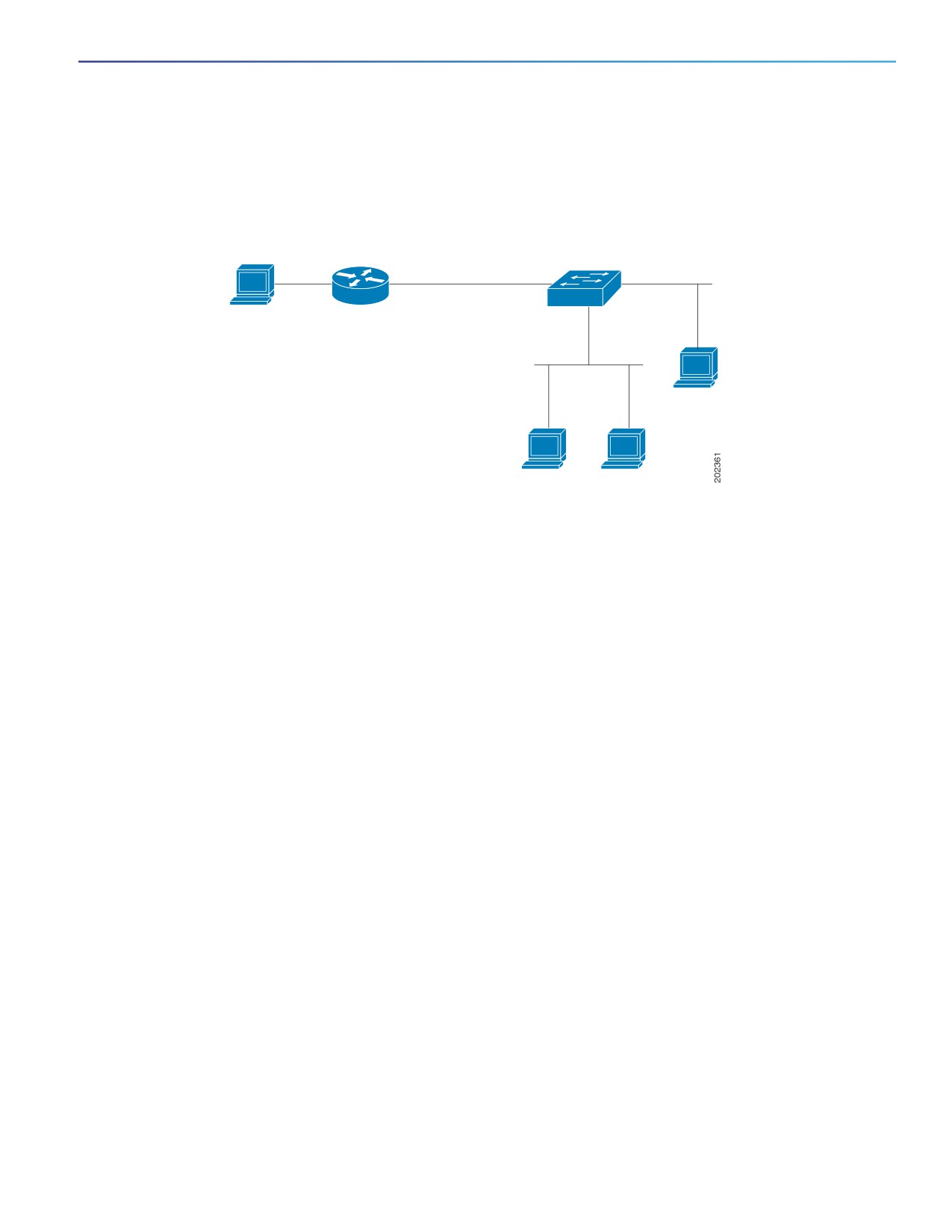
In Figure 88 on page 721, Switch A routed uplink port 25 is connected to the router and PIM stub routing is enabled on
the VLAN 100 interfaces and on Host 3. This configuration allows the directly connected hosts to receive traffic from
multicast source 200.1.1.3. See Configuring PIM Stub Routing, page 733 for more information.
Figure 88
PIM Stub Router Configuration
Switch
A
3.1.1.2.255.255.255.0
Port 25
Port 20
Source
Router
200.1.1.3
VLAN 100
Host 3
Host 1
Host 2
IGMP Helper
PIM stub routing moves routed traffic closer to the end user and reduces network traffic. You can also reduce traffic by
configuring a stub router (switch) with the IGMP helper feature.
You can configure a stub router (switch) with the igmp helper help-address interface configuration command to enable
the switch to send reports to the next-hop interface. Hosts that are not directly connected to a downstream router can
then join a multicast group sourced from an upstream network. The IGMP packets from a host wanting to join a multicast
stream are forwarded upstream to the next-hop device when this feature is configured. When the upstream central router
receives the helper IGMP reports or leaves, it adds or removes the interfaces from its outgoing interface list for that group.
For complete syntax and usage information for the ip igmp helper-address command, see the Cisco IOS IP Multicast
Command Reference.
Auto-RP
This proprietary feature eliminates the need to manually configure the RP information in every router and multilayer switch
in the network. For Auto-RP to work, you configure a Cisco router or multilayer switch as the mapping agent. It uses IP
multicast to learn which routers or switches in the network are possible candidate RPs to receive candidate RP
announcements. Candidate RPs periodically send multicast RP-announce messages to a particular group or group range
to announce their availability.
Mapping agents listen to these candidate RP announcements and use the information to create entries in their
Group-to-RP mapping caches. Only one mapping cache entry is created for any Group-to-RP range received, even if
multiple candidate RPs are sending RP announcements for the same range. As the RP-announce messages arrive, the
mapping agent selects the router or switch with the highest IP address as the active RP and stores this RP address in the
Group-to-RP mapping cache.
Mapping agents periodically multicast the contents of their Group-to-RP mapping cache. Thus, all routers and switches
automatically discover which RP to use for the groups they support. If a router or switch fails to receive RP-discovery
messages and the Group-to-RP mapping information expires, it switches to a statically configured RP that was defined
with the ip pim rp-address global configuration command. If no statically configured RP exists, the router or switch
changes the group to dense-mode operation.
Multiple RPs serve different group ranges or serve as hot backups of each other.
721
Configuring IP Multicast Routing
Information About Cisco’s Implementation of IP Multicast Routing
Bootstrap Router
PIMv2 BSR is another method to distribute group-to-RP mapping information to all PIM routers and multilayer switches
in the network. It eliminates the need to manually configure RP information in every router and switch in the network.
However, instead of using IP multicast to distribute group-to-RP mapping information, BSR uses hop-by-hop flooding
of special BSR messages to distribute the mapping information.
The BSR is elected from a set of candidate routers and switches in the domain that have been configured to function as
BSRs. The election mechanism is similar to the root-bridge election mechanism used in bridged LANs. The BSR election
is based on the BSR priority of the device contained in the BSR messages that are sent hop-by-hop through the network.
Each BSR device examines the message and forwards out all interfaces only the message that has either a higher BSR
priority than its BSR priority or the same BSR priority, but with a higher BSR IP address. Using this method, the BSR is
elected.
The elected BSR sends BSR messages with a TTL of 1. Neighboring PIMv2 routers or multilayer switches receive the
BSR message and multicast it out all other interfaces (except the one on which it was received) with a TTL of 1. In this
way, BSR messages travel hop-by-hop throughout the PIM domain. Because BSR messages contain the IP address of
the current BSR, the flooding mechanism enables candidate RPs to automatically learn which device is the elected BSR.
Candidate RPs send candidate RP advertisements showing the group range for which they are responsible to the BSR,
which stores this information in its local candidate-RP cache. The BSR periodically advertises the contents of this cache
in BSR messages to all other PIM devices in the domain. These messages travel hop-by-hop through the network to all
routers and switches, which store the RP information in the BSR message in their local RP cache. The routers and
switches select the same RP for a given group because they all use a common RP hashing algorithm.
Multicast Forwarding and Reverse Path Check
With unicast routing, routers and multilayer switches forward traffic through the network along a single path from the
source to the destination host whose IP address appears in the destination address field of the IP packet. Each router
and switch along the way makes a unicast forwarding decision, using the destination IP address in the packet, by looking
up the destination address in the unicast routing table and forwarding the packet through the specified interface to the
next hop toward the destination.
With multicasting, the source is sending traffic to an arbitrary group of hosts represented by a multicast group address
in the destination address field of the IP packet. To decide whether to forward or drop an incoming multicast packet, the
router or multilayer switch uses a reverse path forwarding (RPF) check on the packet as follows and shown in Figure 89
on page 723:
1. The router or multilayer switch examines the source address of the arriving multicast packet to decide whether the
packet arrived on an interface that is on the reverse path back to the source.
2. If the packet arrives on the interface leading back to the source, the RPF check is successful and the packet is
forwarded to all interfaces in the outgoing interface list (which might not be all interfaces on the router).
3. If the RPF check fails, the packet is discarded.
Some multicast routing protocols maintain a separate multicast routing table and use it for the RPF check. However, PIM
uses the unicast routing table to perform the RPF check.
Figure 89 on page 723 shows port 2 receiving a multicast packet from source 151.10.3.21. Table 1 shows that the port
on the reverse path to the source is port 1, not port 2. Because the RPF check fails, the multilayer switch discards the
packet. Another multicast packet from source 151.10.3.21 is received on port 1, and the routing table shows this port is
on the reverse path to the source. Because the RPF check passes, the switch forwards the packet to all ports in the
outgoing port list.
722

Configuring IP Multicast Routing
Information About Cisco’s Implementation of IP Multicast Routing
Figure 89
RPF Check
Multicast
Multicast
packet from
packet from
source 151.10.3.21
source 151.10.3.21
is forwarded.
packet is discarded.
Gigabit Ethernet 0/1
Gigabit Ethernet 0/2
Layer 3 switch
Fast Ethernet 0/1
Fast Ethernet 0/2
Network
Port
151.10.0.0/16
Gigabit Ethernet 0/1
198.14.32.0/32
Fast Ethernet 0/1
204.1.16.0/24
Fast Ethernet 0/2
PIM uses both source trees and RP-rooted shared trees to forward datagrams (described in the PIM DM, page 720 and
the PIM SM, page 720). The RPF check is performed differently for each:
If a PIM router or multilayer switch has a source-tree state (that is, an (S,G) entry is present in the multicast routing
table), it performs the RPF check against the IP address of the source of the multicast packet.
If a PIM router or multilayer switch has a shared-tree state (and no explicit source-tree state), it performs the RPF
check on the RP address (which is known when members join the group).
Sparse-mode PIM uses the RPF lookup function to decide where it needs to send joins and prunes:
(S,G) joins (which are source-tree states) are sent toward the source.
(*,G) joins (which are shared-tree states) are sent toward the RP.
Dense-mode PIM uses only source trees and uses RPF as previously described.
Information About Source-Specific Multicast
The Source-Specific Multicast (SSM) feature is an extension of IP multicast in which datagram traffic is forwarded to
receivers from only those multicast sources that the receivers have explicitly joined. For multicast groups configured for
SSM, only SSM distribution trees (no shared trees) are created.
SSM Components Overview
SSM is a datagram delivery model that best supports one-to-many applications, also known as broadcast applications.
SSM is a core networking technology for the Cisco implementation of IP multicast solutions targeted for audio and video
broadcast application environments. The switch supports these components that support the implementation of SSM:
Protocol independent multicast source-specific mode (PIM-SSM)
PIM-SSM is the routing protocol that supports the implementation of SSM and is derived from PIM sparse mode
(PIM-SM).
Internet Group Management Protocol version 3 (IGMPv3)
723
Configuring IP Multicast Routing
Information About Cisco’s Implementation of IP Multicast Routing
To run SSM with IGMPv3, SSM must be supported in the Cisco IOS router, the host where the application is running,
and the application itself.
How SSM Differs from Internet Standard Multicast
The current IP multicast infrastructure in the Internet and many enterprise intranets is based on the PIM-SM protocol and
Multicast Source Discovery Protocol (MSDP). These protocols have the limitations of the Internet Standard Multicast
(ISM) service model. For example, with ISM, the network must maintain knowledge about which hosts in the network are
actively sending multicast traffic.
The ISM service consists of the delivery of IP datagrams from any source to a group of receivers called the multicast host
group. The datagram traffic for the multicast host group consists of datagrams with an arbitrary IP unicast source address
S and the multicast group address G as the IP destination address. Systems receive this traffic by becoming members
of the host group.
Membership in a host group simply requires signalling the host group through IGMP version 1, 2, or 3. In SSM, delivery
of datagrams is based on (S, G) channels. In both SSM and ISM, no signalling is required to become a source. However,
in SSM, receivers must subscribe or unsubscribe to (S, G) channels to receive or not receive traffic from specific sources.
In other words, receivers can receive traffic only from (S, G) channels to which they are subscribed, whereas in ISM,
receivers need not know the IP addresses of sources from which they receive their traffic. The proposed standard
approach for channel subscription signalling use IGMP include mode membership reports, which are supported only in
IGMP version 3.
SSM IP Address Range
SSM can coexist with the ISM service by applying the SSM delivery model to a configured subset of the IP multicast
group address range. Cisco IOS software allows SSM configuration for the IP multicast address range of 224.0.0.0
through 239.255.255.255. When an SSM range is defined, existing IP multicast receiver applications do not receive any
traffic when they try to use an address in the SSM range (unless the application is modified to use an explicit (S, G)
channel subscription).
SSM Operations
An established network, in which IP multicast service is based on PIM-SM, can support SSM services. SSM can also be
deployed alone in a network without the full range of protocols that are required for interdomain PIM-SM (for example,
MSDP, Auto-RP, or bootstrap router [BSR]) if only SSM service is needed.
If SSM is deployed in a network already configured for PIM-SM, only the last-hop routers support SSM. Routers that are
not directly connected to receivers do not require support for SSM. In general, these not-last-hop routers must only run
PIM-SM in the SSM range and might need additional access control configuration to suppress MSDP signalling,
registering, or PIM-SM shared tree operations from occurring within the SSM range.
Use the ip pim ssm global configuration command to configure the SSM range and to enable SSM. This configuration
has the following effects:
For groups within the SSM range, (S, G) channel subscriptions are accepted through IGMPv3 include-mode
membership reports.
PIM operations within the SSM range of addresses change to PIM-SSM, a mode derived from PIM-SM. In this mode,
only PIM (S, G) join and prune messages are generated by the router, and no (S, G) rendezvous point tree (RPT) or
(*, G) RPT messages are generated. Incoming messages related to RPT operations are ignored or rejected, and
incoming PIM register messages are immediately answered with register-stop messages. PIM-SSM is
backward-compatible with PIM-SM unless a router is a last-hop router. Therefore, routers that are not last-hop
routers can run PIM-SM for SSM groups (for example, if they do not yet support SSM).
No MSDP source-active (SA) messages within the SSM range are accepted, generated, or forwarded.
724
Configuring IP Multicast Routing
Information About Cisco’s Implementation of IP Multicast Routing
IGMPv3 Host Signalling
In IGMPv3, hosts signal membership to last hop routers of multicast groups. Hosts can signal group membership with
filtering capabilities with respect to sources. A host can either signal that it wants to receive traffic from all sources
sending to a group except for some specific sources (called exclude mode), or that it wants to receive traffic only from
some specific sources sending to the group (called include mode).
IGMPv3 can operate with both ISM and SSM. In ISM, both exclude and include mode reports are applicable. In SSM, only
include mode reports are accepted by the last-hop router. Exclude mode reports are ignored.
Information About Source Specific Multicast Mapping
The Source Specific Multicast (SSM) mapping feature supports SSM transition when supporting SSM on the end system
is impossible or unwanted due to administrative or technical reasons. You can use SSM mapping to leverage SSM for
video delivery to legacy STBs that do not support IGMPv3 or for applications that do not use the IGMPv3 host stack.
In a typical STB deployment, each TV channel uses one separate IP multicast group and has one active server host
sending the TV channel. A single server can send multiple TV channels, but each to a different group. In this network
environment, if a router receives an IGMPv1 or IGMPv2 membership report for a particular group, the report addresses
the well-known TV server for the TV channel associated with the multicast group.
When SSM mapping is configured, if a router receives an IGMPv1 or IGMPv2 membership report for a particular group,
the router translates this report into one or more channel memberships for the well-known sources associated with this
group.
When the router receives an IGMPv1 or IGMPv2 membership report for a group, the router uses SSM mapping to
determine one or more source IP addresses for the group. SSM mapping then translates the membership report as an
IGMPv3 report and continues as if it had received an IGMPv3 report. The router then sends PIM joins and continues to
be joined to these groups as long as it continues to receive the IGMPv1 or IGMPv2 membership reports, and the SSM
mapping for the group remains the same.
SSM mapping enables the last hop router to determine the source addresses either by a statically configured table on
the router or through a DNS server. When the statically configured table or the DNS mapping changes, the router leaves
the current sources associated with the joined groups.
Static SSM Mapping
With static SSM mapping, you can configure the last hop router to use a static map to determine the sources that are
sending to groups. Static SSM mapping requires that you configure ACLs to define group ranges. Then you can map the
groups permitted by those ACLs to sources by using the ip igmp static ssm-map global configuration command.
You can configure static SSM mapping in smaller networks when a DNS is not needed or to locally override DNS
mappings. When configured, static SSM mappings take precedence over DNS mappings.
DNS-Based SSM Mapping
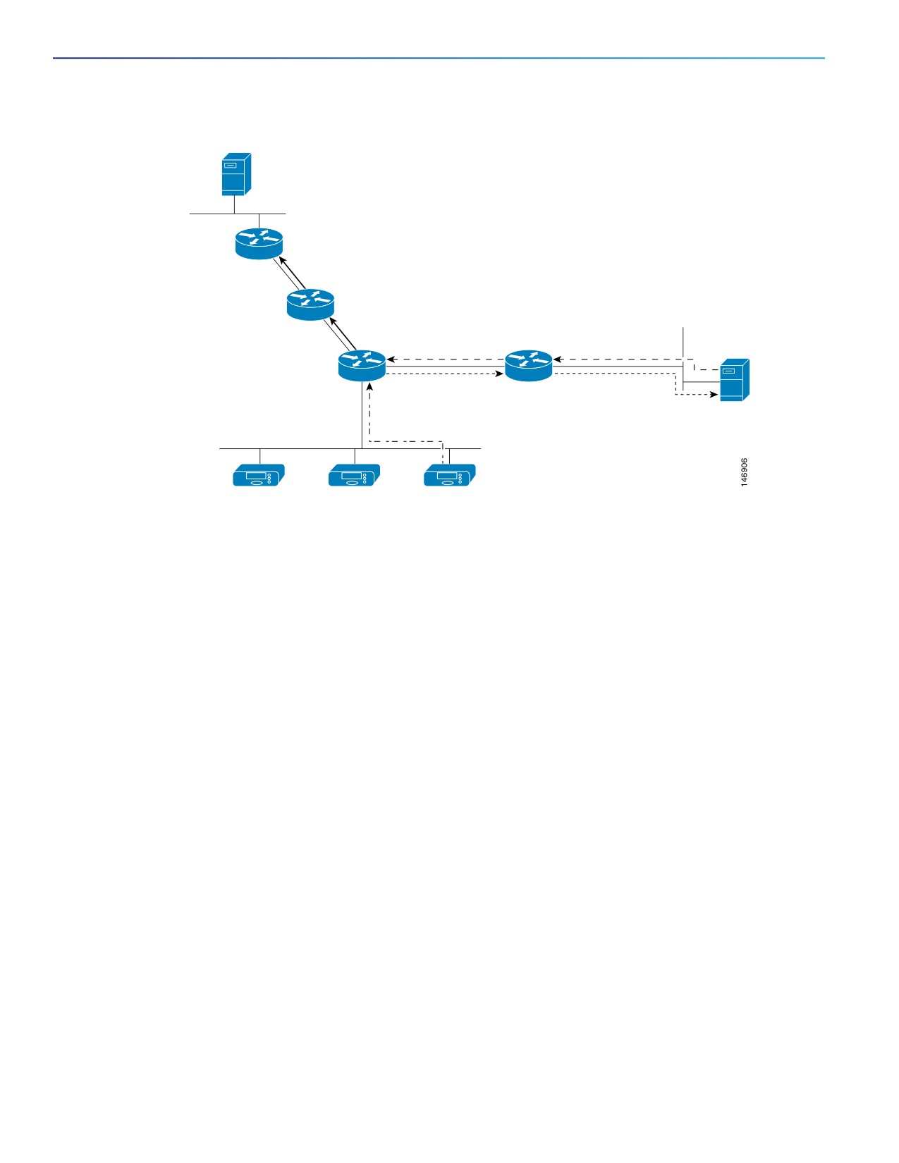
You can use DNS-based SSM mapping to configure the last hop router to perform a reverse DNS lookup to determine
sources sending to groups. When DNS-based SSM mapping is configured, the router constructs a domain name that
includes the group address and performs a reverse lookup into the DNS. The router looks up IP address resource records
and uses them as the source addresses associated with this group. SSM mapping supports up to 20 sources for each
group. The router joins all sources configured for a group (see Figure 90 on page 726).
725
Configuring IP Multicast Routing
Information About Cisco’s Implementation of IP Multicast Routing
Figure 90
DNS-Based SSM-Mapping
Source
(S, G) Join
(S, G) Join
DNS response
DNS server
Reverse DNS lookup
IGMPv2 membership report
STB host 1
STB host 2
STB host 3
The SSM mapping mechanism that enables the last hop router to join multiple sources for a group can provide source
redundancy for a TV broadcast. In this context, the last hop router provides redundancy using SSM mapping to
simultaneously join two video sources for the same TV channel. However, to prevent the last hop router from duplicating
the video traffic, the video sources must use a server-side switchover mechanism. One video source is active, and the
other backup video source is passive. The passive source waits until an active source failure is detected before sending
the video traffic for the TV channel. Thus, the server-side switchover mechanism ensures that only one of the servers is
actively sending video traffic for the TV channel.
To look up one or more source addresses for a group that includes G1, G2, G3, and G4, you must configure these DNS
records on the DNS server:
G4.G3.G2.G1 [multicast-domain] [timeout]IN A source-address-1
IN A source-address-2
IN A source-address-n
Refer to your DNS server documentation for more information about configuring DNS resource records.
Information About PIM Shared Tree and Source Tree
By default, members of a group receive data from senders to the group across a single data-distribution tree rooted at
the RP. Figure 91 on page 727 shows this type of shared-distribution tree. Data from senders is delivered to the RP for
distribution to group members joined to the shared tree.
726