Cisco Industrial Ethernet 4000, 4010 and 5000 Switch Software. Configuration Guide (2022) - page 23
Configuring Network Security with ACLs
Configuring VLAN Maps with ACLs
Step 5
end
Return to global configuration mode.
Step 6
show running-config
Display the access list configuration
Step 7
copy running-config
(Optional) Save your entries in the configuration file.
startup-config
Use the no vlan access-map name global configuration command to delete a map. Use the no vlan access-map name
number global configuration command to delete a single sequence entry from within the map.
Use the no action access-map configuration command to enforce the default action, which is to forward.
VLAN maps do not use the specific permit or deny keywords. To deny a packet by using VLAN maps, create an ACL that
would match the packet, and set the action to drop. A permit in the ACL counts as a match. A deny in the ACL means
no match.
Examples of ACLs and VLAN Maps
These examples show how to create ACLs and VLAN maps for specific purposes.
Example 1
This example shows how to create an ACL and a VLAN map to deny a packet. In the first map, any packets that match
the ip1 ACL (TCP packets) would be dropped. You first create the ip1ACL to permit any TCP packet and no other packets.
Because there is a match clause for IP packets in the VLAN map, the default action is to drop any IP packet that does not
match any of the match clauses.
Switch(config)# ip access-list extended ip1
Switch(config-ext-nacl)# permit tcp any any
Switch(config-ext-nacl)# exit
Switch(config)# vlan access-map map_1 10
Switch(config-access-map)# match ip address ip1
Switch(config-access-map)# action drop
This example shows how to create a VLAN map to permit a packet. ACL ip2 permits UDP packets and any packets that
match the ip2 ACL are forwarded. In this map, any IP packets that did not match any of the previous ACLs (that is, packets
that are not TCP packets or UDP packets) would get dropped.
Switch(config)# ip access-list extended ip2
Switch(config-ext-nacl)# permit udp any any
Switch(config-ext-nacl)# exit
Switch(config)# vlan access-map map_1 20
Switch(config-access-map)# match ip address ip2
Switch(config-access-map)# action forward
Example 2
In this example, the VLAN map has a default action of drop for IP packets and a default action of forward for MAC packets.
Used with standard ACL 101 and extended named access lists igmp-match and tcp-match, the map will have the
following results:
Forward all UDP packets
Drop all IGMP packets
Forward all TCP packets
Drop all other IP packets
607
Configuring Network Security with ACLs
Configuring VLAN Maps with ACLs
Forward all non-IP packets
Switch(config)# access-list 101 permit udp any any
Switch(config)# ip access-list extended igmp-match
Switch(config-ext-nacl)# permit igmp any any
Switch(config)# ip access-list extended tcp-match
Switch(config-ext-nacl)# permit tcp any any
Switch(config-ext-nacl)# exit
Switch(config)# vlan access-map drop-ip-default 10
Switch(config-access-map)# match ip address 101
Switch(config-access-map)# action forward
Switch(config-access-map)# exit
Switch(config)# vlan access-map drop-ip-default 20
Switch(config-access-map)# match ip address igmp-match
Switch(config-access-map)# action drop
Switch(config-access-map)# exit
Switch(config)# vlan access-map drop-ip-default 30
Switch(config-access-map)# match ip address tcp-match
Switch(config-access-map)# action forward
Example 3
In this example, the VLAN map has a default action of drop for MAC packets and a default action of forward for IP packets.
Used with MAC extended access lists good-hosts and good-protocols, the map will have the following results:
Forward MAC packets from hosts 0000.0c00.0111 and 0000.0c00.0211
Forward MAC packets with decnet-iv or vines-ip protocols
Drop all other non-IP packets
Forward all IP packets
Switch(config)# mac access-list extended good-hosts
Switch(config-ext-macl)# permit host 000.0c00.0111 any
Switch(config-ext-macl)# permit host 000.0c00.0211 any
Switch(config-ext-nacl)# exit
Switch(config)# mac access-list extended good-protocols
Switch(config-ext-macl)# permit any any decnet-ip
Switch(config-ext-macl)# permit any any vines-ip
Switch(config-ext-nacl)# exit
Switch(config)# vlan access-map drop-mac-default 10
Switch(config-access-map)# match mac address good-hosts
Switch(config-access-map)# action forward
Switch(config-access-map)# exit
Switch(config)# vlan access-map drop-mac-default 20
Switch(config-access-map)# match mac address good-protocols
Switch(config-access-map)# action forward
Example 4
In this example, the VLAN map has a default action of drop for all packets (IP and non-IP). Used with access lists
tcp-match and good-hosts from Examples 2 and 3, the map will have the following results:
Forward all TCP packets
Forward MAC packets from hosts 0000.0c00.0111 and 0000.0c00.0211
Drop all other IP packets
Drop all other MAC packets
608

Configuring Network Security with ACLs
Configuring VLAN Maps with ACLs
Switch(config)# vlan access-map drop-all-default 10
Switch(config-access-map)# match ip address tcp-match
Switch(config-access-map)# action forward
Switch(config-access-map)# exit
Switch(config)# vlan access-map drop-all-default 20
Switch(config-access-map)# match mac address good-hosts
Switch(config-access-map)# action forward
Applying a VLAN Map to a VLAN
Beginning in privileged EXEC mode, follow these steps to apply a VLAN map to one or more VLANs:
Command
Purpose
Step 1
configure terminal
Enter global configuration mode.
Step 2
vlan filter mapname
Apply the VLAN map to one or more VLAN IDs.
vlan-list list
The list can be a single VLAN ID (22), a consecutive list (10-22), or a string
of VLAN IDs (12, 22, 30).
Note: Spaces around the comma and hyphen are optional.
Step 3
show running-config
Display the access list.
Step 4
copy running-config startup config
(Optional) Save your entries in the configuration file.
To remove the VLAN map, use the no vlan filter mapname vlan-list list global configuration command.
Example below shows how to apply VLAN map 1 to VLANs 20 thru 22:
Switch(config)# vlan filter map 1 vlan-list 20-22
Using VLAN Maps in Your Network
These sections describe some typical uses for VLAN maps:
Wiring Closet Configuration
Denying Access to a Server on Another
Wiring Closet Configuration
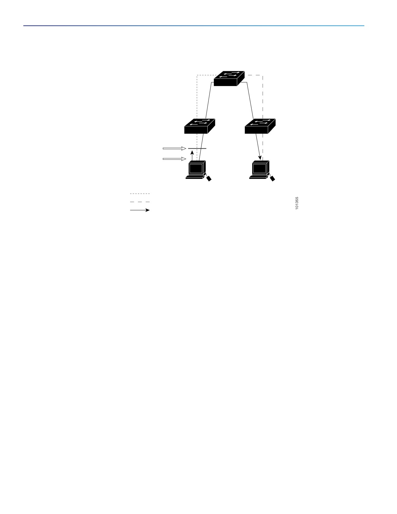
In a wiring closet configuration, routing might not be enabled on the switch. In this configuration, the switch can still
support a VLAN map and a QoS classification ACL. In Figure 37-4, assume that Host X and Host Y are in different VLANs
and are connected to wiring closet switches A and C. Traffic from Host X to Host Y is eventually being routed by Switch
B, a Layer 3 switch with routing enabled. Traffic from Host X to Host Y can be access-controlled at the traffic entry point,
Switch A.
609
Configuring Network Security with ACLs
Additional References
Figure 77
Wiring Closet Configuration
Switch B
Switch A
Switch C
VLAN map: Deny HTTP
from X to Y.
HTTP is dropped
at entry point.
Host X
Host Y
10.1.1.32
10.1.1.34
VLAN 1
VLAN 2
Packet
If you do not want HTTP traffic switched from Host X to Host Y, you can configure a VLAN map on Switch A to drop all
HTTP traffic from Host X (IP address 10.1.1.32) to Host Y (IP address 10.1.1.34) at Switch A and not bridge it to Switch B.
First, define the IP access list http that permits (matches) any TCP traffic on the HTTP port.
Switch(config)# ip access-list extended http
Switch(config-ext-nacl)# permit tcp host 10.1.1.32 host 10.1.1.34 eq www
Switch(config-ext-nacl)# exit
Next, create VLAN access map ‘map2’ so that traffic that matches the http access list is dropped and all other IP traffic
is forwarded.
Switch(config)# vlan access-map map2 10
Switch(config-access-map)# match ip address http
Switch(config-access-map)# action drop
Switch(config-access-map)# exit
Switch(config)# ip access-list extended match_all
Switch(config-ext-nacl)# permit ip any any
Switch(config-ext-nacl)# exit
Switch(config)# vlan access-map map2 20
Switch(config-access-map)# match ip address match_all
Switch(config-access-map)# action forward
Then, apply VLAN access map map2 to VLAN 1.
Switch(config)# vlan filter map2 vlan 1
Additional References
The following sections provide references related to switch administration:
610
Configuring Network Security with ACLs
Additional References
Related Documents
Related Topic
Document Title
Cisco IOS basic commands
Cisco IOS Configuration Fundamentals Command Reference
Cisco IOS multicast commands
Cisco IOS IP Command Reference, Volume 3 of 3:Multicast
Cisco IOS IP Addressing and Services configuration
Cisco IOS IP Configuration Guide
Cisco IOS ACL configuration
Cisco IOS IP Command Reference, Volume 1 of 3: Addressing and
Services
Cisco IOS Security Configuration Guide
Standards
Standards
Title
No new or modified standards are supported by this
—
feature, and support for existing standards has not
been modified by this feature.
MIBs
MIBs
MIBs Link
—
To locate and download MIBs using Cisco IOS XR software, use the
Cisco MIB Locator found at the following URL and choose a platform
under the Cisco Access Products menu:
RFCs
RFCs
Title
No new or modified RFCs are supported by this
—
feature, and support for existing RFCs has not been
modified by this feature.
Technical Assistance
Description
Link
The Cisco Technical Support website contains
thousands of pages of searchable technical content,
including links to products, technologies, solutions,
technical tips, and tools. Registered Cisco.com users
can log in from this page to access even more content.
611
Configuring Network Security with ACLs
Additional References
612
Configuring QoS
This chapter describes how to configure quality of service (QoS) by using the modular QoS command-line interface (CLI),
or MQC, commands on the Cisco IE switch. With QoS, you can provide preferential treatment to certain types of traffic
at the expense of others. When QoS is not configured, the switch offers best-effort service to each packet, regardless
of the packet contents or size. It sends the packets without any assurance of reliability, delay bounds, or throughput.
MQC provides a comprehensive hierarchical configuration framework for prioritizing or limiting specific streams of traffic.
Note: IPv6 QoS is not supported.
For more information about Cisco IOS MQC commands, see the “Cisco IOS Quality of Service Solutions Command
Reference” at this site:
Understanding QoS, page 613
QoS Treatment for Performance-Monitoring Protocols, page 632
Configuring QoS, page 642
Displaying QoS Information, page 687
Configuration Examples for Policy Maps, page 688
Understanding QoS
Typically, networks operate on a best-effort delivery basis, which means that all traffic has equal priority and an equal
chance of being delivered in a timely manner. When congestion occurs, all traffic has an equal chance of being dropped.
When you configure the QoS feature, you can select specific network traffic, prioritize it according to its relative
importance, and use traffic-management techniques to provide preferential treatment. Implementing QoS in your
network makes network performance more predictable and bandwidth utilization more effective.
Figure 78 on page 613 shows the MQC model.
Figure 78
Modular QoS CLI Model
Classification
Policing
Marking
Congestion
Queuing
Avoidance
Policer
Congestion
Scheduling
Drops
Drops
Basic QoS includes these actions.
613
Configuring QoS
Understanding QoS
Packet classification organizes traffic on the basis of whether or not the traffic matches a specific criteria. When a
packet is received, the switch identifies all key packet fields: class of service (CoS), Differentiated Services Code
Point (DSCP), or IP precedence. The switch classifies the packet based on this content or based on an
access-control list lookup. For more information, see Classification, page 617.
Packet policing determines whether a packet is in or out of profile by comparing the rate of the incoming traffic to
the configured policer. You can control the traffic flow for packets that conform to or exceed the configured policer.
You can configure a committed information rate (CIR) and peak information rate (PIR) and set actions to perform on
packets that conform to the CIR and PIR (conform-action), packets that conform to the PIR, but not the CIR
(exceed-action), and packets that exceed the PIR value (violate-action). For more information, see Policing,
page 626.
Packet prioritization or marking evaluates the classification and policer information to determine the action to take.
All packets that belong to a classification can be remarked. When you configure a policer, packets that meet or
exceed the permitted bandwidth requirements (bits per second) can be conditionally passed through, dropped, or
reclassified. For more information, see Marking, page 631.
Congestion management uses queuing and scheduling algorithms to queue and sort traffic that is leaving a port. The
switch supports these scheduling and traffic-limiting features: class-based weighted fair queuing (CBWFQ),
class-based traffic shaping, port shaping, and class-based priority queuing. You can provide guaranteed bandwidth
to a particular class of traffic while still servicing other traffic queues. For more information, see Congestion
Management and Scheduling, page 635.
Queuing on the switch is enhanced with the weighted tail-drop (WTD) algorithm, a congestion-avoidance
mechanism. WTD differentiates traffic classes and regulates the queue size (in number of packets) based on the
classification. For more information, see Congestion Avoidance and Queuing, page 639.
This section includes information about these topics:
Modular QoS CLI, page 614
Input and Output Policies, page 615
Classification, page 617
Table Maps, page 625
Policing, page 626
Marking, page 631
Congestion Management and Scheduling, page 635
Congestion Avoidance and Queuing, page 639
Modular QoS CLI
Modular QoS CLI (MQC) allows users to create traffic policies and attach these policies to interfaces. A traffic policy
contains a traffic class and one or more QoS features. You use a traffic class to classify traffic, and the QoS features in
the traffic policy determine how to treat the classified traffic.
Modular QoS CLI configuration includes these steps:
1. Define a traffic class.
Use the class-map [match-all | match-any] class-map-name global configuration command to define a traffic class
and to enter class-map configuration mode. A traffic class contains three elements: a name, an instruction on how to
evaluate the configured match commands (if more than one match command is configured in the class map), and a
series of match commands
You name the traffic class in the class-map command line to enter class-map configuration mode.
614
Configuring QoS
Understanding QoS
You can optionally include keywords to evaluate these match commands by entering class-map match-any or
class-map match-all. If you specify match-any, the traffic being evaluated must match one of the specified criteria.
If you specify match-all, the traffic being evaluated must match all of the specified criteria. A match-all class map
can contain only one match statement, but a match-any class map can contain multiple match statements.
If you do not enter match-all or match-any, the default is to match all.
You use the match class-map configuration commands to specify criteria for classifying packets. If a packet matches
the specified criteria, that packet is considered a member of the class and is forwarded according to the QoS
specifications set in the traffic policy. Packets that fail to meet any of the matching criteria are classified as members
of the default traffic class.
2. Create a traffic policy to associate the traffic class with one or more QoS features.
You use the policy-map policy-map-name global configuration command to create a traffic policy and to enter
policy-map configuration mode. A traffic policy defines the QoS features to associate with the specified traffic class. A
traffic policy contains three elements: a name, a traffic class (specified with the class policy-map configuration
command), and the QoS policies configured in the class.
You name the traffic policy in the policy-map command line to enter policy-map configuration mode.
In policy-map configuration mode, enter the name of the traffic class used to classify traffic to the specified policy,
and enter policy-map class configuration mode.
In policy-map class configuration mode, you can enter the QoS features to apply to the classified traffic. These
include using the set, police, or police aggregate commands for input policy maps or the bandwidth, priority,
queue-limit or shape average commands for output policy maps.
Note: A packet can match only one traffic class within a traffic policy. If a packet matches more than one traffic class in
the traffic policy, the first traffic class defined in the policy is used. To configure more than one match criterion for
packets, you can associate multiple traffic classes with a single traffic policy.
3. Attach the traffic policy to an interface.
You use the service-policy interface configuration command to attach the policy map to an interface for packets entering
or leaving the interface. You must specify whether the traffic policy characteristics should be applied to incoming or
outgoing packets. For example, entering the service-policy output class1 interface configuration command attaches
all the characteristics of the traffic policy named class1 to the specified interface. All packets leaving the specified
interface are evaluated according to the criteria specified in the traffic policy named class1.
Input and Output Policies
Policy maps are either input policy maps or output policy maps, attached to packets as they enter or leave the switch by
service policies applied to interfaces. Input policy maps perform policing and marking on received traffic. Policed packets
can be dropped or reduced in priority (marked down) if they exceed the maximum permitted rates. Output policy maps
perform scheduling and queuing on traffic as it leaves the switch.
Input policies and output policies have the same basic structure; the difference is in the characteristics that they regulate.
Figure 79 on page 616 shows the relationship of input and output policies.
You can configure a maximum of 256 policy maps.
The number of configurable policer profiles on the switch is 256. The number of supported policer instances on the
switch is 1024 minus 1 more than the number of interfaces on the switch. On a 24-port switch, the number of available
policer instances is 999. You can use a policer profile in multiple instances.
You can apply one input policy map and one output policy map to an interface.
615
Configuring QoS
Understanding QoS
When CPU protection is enabled (the default), you can configure 45 ingress policers per port. If you disable CPU
protection by entering the no policer cpu uni all global configuration command and reloading the switch, you can
configure a maximum of 63 policers per port (62 on every 4th port) for user-defined classes and one for class-default.
You can enter the show policer cpu uni-eni {drop | rate} privileged EXEC command to see if CPU protection is enabled.
Figure 79
Input and Output Policy Relationship
Apply
Apply
input
output
policy
policy
Ingress
Switching
Egress
port
and
port
forwarding
Apply
Apply
output
input
policy
policy
Input Policy Maps
Input policy map classification criteria include matching a CoS, a DSCP, or an IP precedence value or matching an access
control list (ACL) or VLAN ID (for per-port, per-VLAN QoS). Input policy maps can have any of these actions:
Setting or marking a CoS, a DSCP, an IP precedence, or QoS group value
Individual policing
Aggregate policing
Only input policies provide matching on access groups or VLAN IDs, and only output policies provide matching on QoS
groups. You can assign a QoS group number in an input policy and match it in the output policy. The class class-default
is used in a policy map for any traffic that does not explicitly match any other class in the policy map. Input policy maps
do not support queuing and scheduling keywords, such as bandwidth, queue-limit, priority, and shape average.
An input policy map can have a maximum of 64 classes plus class-default. You can configure a maximum of 64 classes
in an input policy.
Output Policy Maps
Output policy map classification criteria include matching a CoS, a DSCP, an IP precedence, or a QoS group value. Output
policy maps can have any of these actions:
Queuing (queue-limit)
Scheduling (bandwidth, priority, and shape average)
Output policy maps do not support matching of access groups. You can use QoS groups as an alternative by matching
the appropriate access group in the input policy map and setting a QoS group. In the output policy map, you can then
match the QoS group. See Classification Based on QoS Groups, page 622 for more information.
Output policies do not support marking or policing (except in the case of priority with policing). There is no egress packet
marking on the switch (no set command in an output policy).
The class class-default is used in a policy map for any traffic that does not explicitly match any other class in the policy
map. There can be a maximum of four classes in the output policy map (including class-default) because egress ports
have a maximum of four queues.
An output policy map attached to an egress port can match only the packets that have already been matched by an input
policy map attached to the ingress port for the packets. You can attach an output policy map to any or all ports on the
switch. The switch supports configuration and attachment of a unique output policy map for each port. However, these
616
Configuring QoS
Understanding QoS
output policy maps can contain only three unique configurations of queue limits. These three unique queue-limit
configurations can be included in as many output policy maps as there are ports on the switch. There are no limitations
on the configurations of bandwidth, priority, or shaping.
You can configure the output policy classification criteria for CPU-generated traffic by using the cpu traffic qos [cos
value | dscp value | precedence value | qos-group value] global configuration command.
Classification
Classification distinguishes one kind of traffic from another by examining the fields in the packet header. When a packet
is received, the switch examines the header and identifies all key packet fields. A packet can be classified based on an
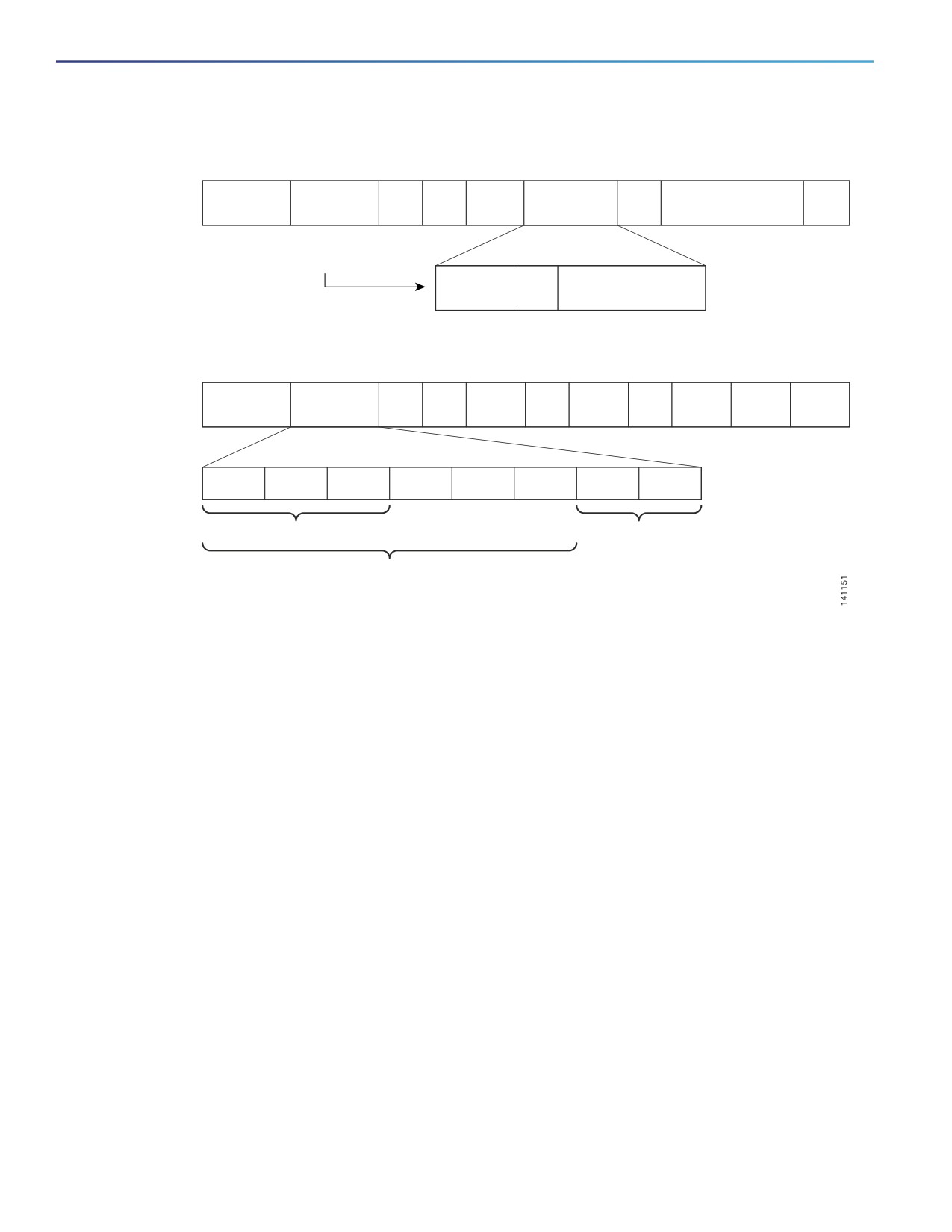
ACL, on the DSCP, the CoS, or the IP precedence value in the packet, or by the VLAN ID. Figure 80 on page 618 has
examples of classification information carried in a Layer 2 or a Layer 3 IP packet header, using six bits from the
deprecated IP type of service (ToS) field to carry the classification information.
On ports configured as Layer 2 IEEE 802.1Q trunks, all traffic is in 802.1Q frames except for traffic in the native VLAN.
Layer 2 802.1Q frame headers have a 2-byte Tag Control Information field that carries the CoS value, called the User
Priority bits, in the three most-significant bits, and the VLAN ID value in the 12 least-significant bits. Other frame
types cannot carry Layer 2 CoS values.
Layer 2 CoS values range from 0 to 7.
Layer 3 IP packets can carry either an IP precedence value or a DSCP value. QoS supports the use of either value
because DSCP values are backward-compatible with IP precedence values.
IP precedence values range from 0 to 7. DSCP values range from 0 to 63.
Output remarking is based on the Layer 2 or Layer 3 marking type, marking value and packet type.
617
Configuring QoS
Understanding QoS
Figure 80
QoS Classification Layers in Frames and Packets
Layer 2 IEEE 802.1Q and IEEE 802.1p Frame
Start frame
TAG
Preamble
DA
SA
Type
PT
Data
FCS
delimiter
2 Bytes
3 bits used for CoS
(IEEE 802.1p user priority)
PRI
CFI
VLAN ID
Layer 3 IPv4 Packet
Version
ToS
Len
ID
Offset
TTL
Proto
FCS
IP-SA
IP-DA
Data
length
1 Byte
7
6
5
4
3
2
1
0
IP precedence
Flow control
for DSCP
DSCP
Standard IPv4:
MSBs called IP precedence
These sections contain additional information about classification:
Class Maps, page 618
The match Command, page 619
Classification Based on Layer 2 CoS, page 619
Classification Based on IP Precedence, page 619
Classification Based on IP DSCP, page 620
Classification Comparisons, page 621
Classification Based on QoS ACLs, page 622
Classification Based on QoS Groups, page 622
Classification Based on VLAN IDs, page 623
Class Maps
As explained previously, you use an MQC class map to name a specific traffic flow (or class) and to isolate it from all
other traffic. A class map defines the criteria used to match against a specific traffic flow to further classify it. If you have
more than one type of traffic that you want to classify, you can create another class map and use a different name. When
you enter the class-map command with a class-map name, the switch enters the class-map configuration mode. In this
mode, you define the match criterion for the traffic by using the match class-map configuration command. After a packet
is matched against the class-map criteria, it is acted on by the associated action specified in a policy map.
618
Configuring QoS
Understanding QoS
You can match more than one criterion for classification. You can also create a class map that requires that all matching
criteria in the class map be in the packet header by using the class map match-all class-map name global configuration
command to enter class map configuration mode.
Note: You can configure only one match entry in a match-all class map.
You can use the class map match-any class-map name global configuration command to define a classification with
any of the listed criteria.
Note: If you do not enter match-all or match-any, the default is to match all. A match-all class map cannot have more
than one classification criterion (match statement). A class map with no match condition has a default of match all.
The match Command
To configure the type of content used to classify packets, you use the match class-map configuration command to
specify the classification criteria. If a packet matches the configured criteria, it belongs to a specific class and is
forwarded according to the specified policy. For example, you can use the match class-map command with CoS, IP
DSCP, and IP precedence values. These values are referred to as markings on a packet. You can also match an access
group, a QoS group, or a VLAN ID or ID range for per-port, per-VLAN QoS.
For an input policy map, you cannot configure an IP classification (match ip dscp, match ip precedence, match
access-group for an IP ACL) and a non-IP classification (match cos or match access-group for a MAC ACL) in the
same policy map or class map.
When an input policy map with only Layer 2 classification is attached to a routed port or a switch port containing a
routed switch virtual interface (SVI), the service policy acts only on switching eligible traffic and not on routing eligible
traffic.
On an 802.1Q tunnel port, you can use only an input policy map with Layer 2 classification based on MAC ACLs to
classify traffic. Input policy maps with Layer 3 classification, match Layer 2 CoS classification, or per-port, per-VLAN
policies are not supported on tunnel ports.
In an output policy map, no two class maps can have the same classification criteria, that is, the same match
qualifiers and values.
This example shows how to create a class map example to define a class that matches any of the listed criteria. In this
example, if a packet is received with the DSCP equal to 32 or a 40, the packet is identified (classified) by the class map.
Switch(config)# class-map match-any example
Switch(config-cmap)# match ip dscp 32
Switch(config-cmap)# match ip dscp 40
Switch(config-cmap)# exit
Classification Based on Layer 2 CoS
You can use the match command to classify Layer 2 traffic based on the CoS value, which ranges from 0 to 7.
Note: A match cos command is supported only on Layer 2 802.1Q trunk ports.
This example shows how to create a class map to match a CoS value of 5:
Switch(config)# class-map premium
Switch(config-cmap)# match cos 5
Switch(config-cmap)# exit
Classification Based on IP Precedence
You can classify IPv4 traffic based on the packet IP precedence values, which range from 0 to 7.
619
Configuring QoS
Understanding QoS
This example shows how to create a class map to match an IP precedence value of 4:
Switch(config)# class-map sample
Switch(config-cmap)# match ip precedence 4
Switch(config-cmap)# exit
Classification Based on IP DSCP
When you classify IPv4 traffic based on IP DSCP value, and enter the match ip dscp class-map configuration command,
you have several classification options:
Entering a specific DSCP value (0 to 63).
Using the Default service, which corresponds to an IP precedence and DSCP value of 0. The default per-hop
behavior (PHB) is usually best-effort service.
Using Assured Forwarding (AF) by entering the binary representation of the DSCP value. AF sets the relative
probability that a specific class of packets is forwarded when congestion occurs and the traffic does not exceed the
maximum permitted rate. AF per-hop behavior provides delivery of IP packets in four different AF classes: AF11-13
(the highest), AF21-23, AF31-33, and AF41-43 (the lowest). Each AF class could be allocated a specific amount of
buffer space and drop probabilities, specified by the binary form of the DSCP number. When congestion occurs, the
drop precedence of a packet determines the relative importance of the packet within the class. An AF41 provides
the best probability of a packet being forwarded from one end of the network to the other.
Entering Class Selector (CS) service values of 1 to 7, corresponding to IP precedence bits in the ToS field of the
packet.
Using Expedited Forwarding (EF) to specify a low-latency path. This corresponds to a DSCP value of 46. EF services
use priority queuing to preempt lower priority traffic classes.
This display shows the available classification options:
Switch(config-cmap)# match ip dscp ?
<0-63>
Differentiated services codepoint value
af11
Match packets with AF11 dscp (001010)
af12
Match packets with AF12 dscp (001100)
af13
Match packets with AF13 dscp (001110)
af21
Match packets with AF21 dscp (010010)
af22
Match packets with AF22 dscp (010100)
af23
Match packets with AF23 dscp (010110)
af31
Match packets with AF31 dscp (011010)
af32
Match packets with AF32 dscp (011100)
af33
Match packets with AF33 dscp (011110)
af41
Match packets with AF41 dscp (100010)
af42
Match packets with AF42 dscp (100100)
af43
Match packets with AF43 dscp (100110)
cs1
Match packets with CS1(precedence 1) dscp (001000)
cs2
Match packets with CS2(precedence 2) dscp (010000)
cs3
Match packets with CS3(precedence 3) dscp (011000)
cs4
Match packets with CS4(precedence 4) dscp (100000)
cs5
Match packets with CS5(precedence 5) dscp (101000)
cs6
Match packets with CS6(precedence 6) dscp (110000)
cs7
Match packets with CS7(precedence 7) dscp (111000)
default
Match packets with default dscp (000000)
ef
Match packets with EF dscp (101110)
For more information on DSCP prioritization, see RFC-2597 (AF per-hop behavior), RFC-2598 (EF), or RFC-2475
(DSCP).
620

Configuring QoS
Understanding QoS
802.1Q Tunneling CoS Mapping
The switch supports VLAN mapping from the customer VLAN-ID (C-VLAN) to a service-provider VLAN-ID (S-VLAN). For
QoS, the switch can set the service-provider CoS (S-CoS) from either the customer CoS (C-CoS) or the customer DSCP
(C-DSCP) value, and can map the inner CoS to the outer CoS for any traffic with traditional 802.1Q tunneling (QinQ) or
selective QinQ VLAN mapping. This default allows copying the customer CoS into the service provider network.
The switch supports C-CoS to S-CoS propagation for traditional QinQ and for selective QinQ on trunk ports. This is the
default behavior and does not require configuration. When you configure traditional QinQ or selective QinQ on Layer 2
trunk ports using 1-to-2 VLAN mapping, the switch also allows setting the S-CoS from C-DSCP.
For traffic entering the switch on 802.1Q tunnel ports or trunk ports configured for VLAN mapping, the switch has the
ability to examine the customer packet header and set the service-provider CoS value (S-CoS) from either the customer
CoS value or the customer DSCP value.
Configuring CoS matching on 802.1Q mapped ports is handled in this way:
On interfaces configured for 802.1Q tunneling (on tunnel or trunk ports) or selective 802.1Q (on trunk ports), the
CoS value of the VLAN tag (inner VLAN or C-VLAN) received on the interface (C-CoS) is automatically reflected in
the tunnel VLAN tag (outer VLAN or S-VLAN) by default.
The set cos policy-map class configuration commands always apply to the outer-most VLAN tag after processing
is complete, that is the S-VLAN-ID. For example, in 802.1Q tunnels, entering a set cos command changes only the
CoS value of the outer tag of the encapsulated packet.
When you configure a policy by entering the match dscp class map configuration command and you enter the set
cos policy-map class configuration command for QinQ and selective QinQ mapping interfaces, a DSCP match sets
the outer CoS of the encapsulated value.
You can set DSCP based on matching the outer VLAN.
If you enter the match cos command on interfaces configured for traditional QinQ or for selective QinQ mapping,
the match is to the outer CoS, which is the reflected inner Cos (C-CoS).
Classification Comparisons
Table 57 on page 621 shows suggested IP DSCP, IP precedence, and CoS values for typical traffic types.
Table 57
Typical Traffic Classifications
Traffic Type
DSCP
DSCP
IP
CoS
per-hop
(decimal)
Precedence
Voice-bearer—traffic in a priority queue or the queue with the
EF
46
5
5
highest service weight and lowest drop priority.
Voice control—signalling traffic, related to call setup, from a
AF31
26
3
3
voice gateway or a voice application server.
Video conferencing—in most networks, video conferencing over
AF41
34
4
4
IP has similar loss, delay, and delay variation requirements as
voice over IP traffic.
Streaming video—relatively high bandwidth applications with a
AF13
14
1
1
high tolerance for loss, delay, and delay variation. Usually
considered more important than regular background
applications such as e-mail and web browsing.
621
Configuring QoS
Understanding QoS
Table 57
Typical Traffic Classifications (continued)
Traffic Type
DSCP
DSCP
IP
CoS
per-hop
(decimal)
Precedence
Mission critical date (gold data)—delay-sensitive applications
critical to the operation of an enterprise.
Level 1
AF21
18
2
2
Level 2
AF22
20
2
2
Level 3
AF23
22
2
2
Less critical data (silver data)—noncritical, but relatively
important data.
Level 1
AF11
10
1
1
Level 2
AF12
12
1
1
Level 3
AF13
14
1
1
Best-effort data (bronze data)—other traffic, including all
Default
0
0
0
noninteractive traffic, regardless of importance.
Less than best-effort data—noncritical, bandwidth-intensive
data traffic given the least preference. This is the first traffic type
to be dropped.
Level 1
2
0
0
Level 2
4
0
0
Level 3
6
0
0
Classification Based on QoS ACLs
Packets can also be classified in input policy maps based on an ACL lookup. The ACL classification is communicated to
an output policy by assigning a QoS group or number in the input policy map. To classify based on ACL lookup, you first
create an IP or MAC ACL. Configure a class map and use the match access-group {acl-number | acl name} class-map
configuration command, and attach the class map to a policy map.
Note: You cannot configure match access-group for an output policy map.
You can use IP standard, IP extended, or Layer 2 MAC ACLs to define a group of packets with the same characteristics
(a class). You use the access-list global configuration command to configure IP ACLS to classify IP traffic based on Layer
3 and Layer 4 parameters. You use the mac access-list extended global configuration command to configure Layer 2
MAC ACLs to classify IP and non-IP traffic based on Layer 2 parameters.
Note: You cannot match IP fragments against configured IP extended ACLs to enforce QoS. IP fragments are sent as
best-effort. IP fragments are denoted by fields in the IP header.
You can use only ACLs with a permit action in a match access-group command. ACLs with a deny action are never
matched in a QoS policy.
Note: Only one access-group is supported per class for an input policy map.
Classification Based on QoS Groups
A QoS group is an internal label used by the switch to identify packets as a members of a specific class. The label is not
part of the packet header and is restricted to the switch that sets the label. QoS groups provide a way to tag a packet
for subsequent QoS action without explicitly marking (changing) the packet. You can then communicate an ACL match
from an input policy map to an output policy map.
A QoS group is identified at ingress and used at egress; it is assigned in an input policy to identify packets in an output
policy. See on page 622. The QoS groups help aggregate different classes of input traffic for a specific action in an
output policy.
622
Configuring QoS
Understanding QoS
Figure 81
QoS Groups
1. Classify traffic
Switching
1. Match qos-group
2. Set qos-group
functions
2. Output policy
You can use QoS groups to aggregate multiple input streams across input classes and policy maps for the same QoS
treatment on the egress port. Assign the same QoS group number in the input policy map to all streams that require the
same egress treatment, and match to the QoS group number in the output policy map to specify the required queuing
and scheduling actions.
You can also use QoS groups to identify traffic entering a particular interface if the traffic must be treated differently at
the output based on the input interface.
You can use QoS groups to configure per-port, per-VLAN QoS output policies on the egress interface for bridged traffic
on the VLAN. Assign a QoS group number to a VLAN on the ingress interface by configuring a per-port, per-VLAN input
policy. Then use the same QoS-group number for classification at the egress. Because the VLAN of bridged traffic does
not change during forwarding through the switch, the QoS-group number assigned to the ingress VLAN can be used on
the egress interface to identify the same VLAN.
You can use the cpu traffic qos [cos value | dscp value | precedence value | qos-group value] global configuration
command to configure a QoS group number for CPU-generated traffic.
Independently you can assign QoS-group numbers at the ingress to any combination of interfaces, VLANs, traffic flows,
and aggregated traffic. To assign QoS-group numbers, configure a QoS group marking in an input policy map, along with
any other marking or policing actions required in the input policy map for the same service class. This allows the input
marking and policing functions to be decoupled from the egress classification function if necessary because only the
QoS group must be used for egress classification.
To communicate an ACL classification to an output policy, you assign a QoS number to specify packets at ingress. This
example identifies specific packets as part of QoS group 1 for later processing in an output policy:
Switch(config)# policy-map in-gold-policy
Switch(config-pmap)# class in-class1
Switch(config-pmap-c)# set qos-group 1
Switch(config-cmap-c)# exit
Switch(config-cmap)# exit
You use the set qos-group command only in an input policy. The assigned QoS group identification is subsequently used
in an output policy with no mark or change to the packet. You use the match qos-group in the output policy.
Note: You cannot configure match qos-group for an input policy map.
This example creates an output policy to match the QoS group created in the input policy map in-gold-policy. Traffic
internally tagged as qos-group 1 is identified and processed by the output policy.
Switch(config)# class-map out-class1
Switch(config-cmap)# match qos-group 1
Switch(config-cmap)# exit
The switch supports a maximum of 100 QoS groups.
Classification Based on VLAN IDs
With classification based on VLAN IDs, you can apply QoS policies to frames carried on a user-specified VLAN for a given
interface. Per-VLAN classification is not required on access ports because access ports carry traffic for a single VLAN.
If you try to attach an input per-port, per VLAN hierarchical policy to a port that is not a trunk port, the configuration is
rejected.
623
Configuring QoS
Understanding QoS
The switch supports two policy levels: a parent level and a child level. With the QoS parent-child structure, you can
reference a child policy in a parent policy to provide additional control of a specific traffic type. For per-port, per-VLAN
QoS, the parent-level class map specifies only the VLAN match criteria, and the child-level class maps provide more
detailed classification for frames matching the parent-level class map.You can configure multiple service classes at the
parent level to match different combinations of VLANs, and you can apply independent QoS policies to each parent
service class using any child policy map.
Note: A per-port, per-VLAN parent-level class map supports only a child-policy association; it does not allow any actions
to be configured. In addition, for a parent-level class map, you cannot configure an action or a child-policy association
for the class class-default.
Per-port, per-VLAN QoS has these limitations:
You can apply a per-port, per-VLAN hierarchical policy map only to trunk ports.
You can configure classification based on VLAN ID only in the parent level of a per-port, per-VLAN hierarchical policy
map.
When the child policy map attached to a VLAN or set of VLANs contains only Layer 3 classification (match ip dscp,
match ip precedence, match IP ACL), you must be careful to ensure that these VLANs are not carried on any port
other than the one on which this per-port, per-VLAN policy is attached. Not following this restriction could result in
improper QoS behavior for traffic ingressing the switch on these VLANs.
We also recommend that you restrict VLAN membership on the trunk ports to which the per-port, per-VLAN is
applied by using the switchport trunk allowed vlan interface configuration command. Overlapping VLAN
membership between trunk ports that have per-port, per-VLAN policies with Layer 3 classification could also result
in unexpected QoS behavior.
In this example, the class maps in the child-level policy map specify matching criteria for voice, data, and video traffic,
and the child policy map sets the action for input policing each type of traffic. The parent-level policy map specifies the
VLANs to which the child policy maps are applied on the specified port.
Switch(config)# class-map match-any dscp-1 data
Switch(config-cmap)# match ip dscp 1
Switch(config-cmap)# exit
Switch(config)# class-map match-any dscp-23 video
Switch(config-cmap)# match ip dscp 23
Switch(config-cmap)# exit
Switch(config)# class-map match-any dscp-63 voice
Switch(config-cmap)# match ip dscp-63
Switch(config-cmap)# exit
Switch(config)# class-map match-any customer-1-vlan
Switch(config-cmap)# match vlan 100
Switch(config-cmap)# match vlan 200
Switch(config-cmap)# match vlan 300
Switch(config-cmap)# exit
Note: You can also enter the match criteria as match vlan 100 200 300 with the same result.
Switch(config)# policy-map child policy-1
Switch(config-pmap)# class dscp-63 voice
Switch(config-pmap-c)# police cir 10000000 bc 50000
Switch(config-pmap-c)# conform-action set-cos-transmit 5
Switch(config-pmap-c)# exceed-action drop
Switch(config-pmap-c)# exit
Switch(config-pmap)# class dscp-1 data
Switch(config-pmap-c)# set cos 0
Switch(config-pmap-c)# exit
Switch(config-pmap)# class dscp-23 video
Switch(config-pmap-c)# set cos 4
Switch(config-pmap-c)# set ip precedence 4
Switch(config-pmap-c)# exit
Switch(config)# policy-map parent-customer-1
624
Configuring QoS
Understanding QoS
Switch(config-pmap)# class customer-1-vlan
Switch(config-pmap-c)# service-policy ingress-policy-1
Switch(config-pmap-c)# exit
Switch(config)# interface fastethernet0/1
Switch(config-if)# switchport mode trunk
Switch(config-if)# service-policy input customer-1-ingress
Switch(config-pmap-c)# exit
Note: Each per-port, per-VLAN parent policy class, except class-default, can have a child policy association.
see Configuring Per-Port Per-VLAN QoS with Hierarchical Input Policy Maps, page 665 for configuration information,
including configuration guidelines and limitations.
Table Maps
You can use table maps to manage a large number of traffic flows with a single command. You can specify table maps
in set commands and use them as mark-down mapping for the policers. You can also use table maps to map an incoming
QoS marking to a replacement marking without having to configure a large number of explicit matches and sets. Table
maps are used only in input policy maps.
Table maps can be used to:
Correlate specific CoS, DSCP, or IP precedence values to specific CoS, DSCP, or IP precedence values
Mark down a CoS, DSCP, or IP precedence value
Assign defaults for unmapped values
A table map includes one of these default actions:
default default-value—applies a specific default value (0 to 63) for all unmapped values
default copy—maps all unmapped values to the equivalent value in another qualifier
default ignore—makes no changes for unmapped values
This example creates a table to map specific CoS values to DSCP values. The default command maps all unmapped
CoS values to a DSCP value of 63.
Switch(config)# table-map cos-dscp-tablemap
Switch(config-tablemap)# map from 5 to 46
Switch(config-tablemap)# map from 6 to 56
Switch(config-tablemap)# map from 7 to 57
Switch(config-tablemap)# default 63
Switch(config-tablemap)# exit
The switch supports a maximum of 256 unique table maps. You can enter up to 64 different map from-to entries in a
table map. These table maps are supported on the switch:
DSCP to CoS
DSCP to precedence
DSCP to DSCP
CoS to DSCP
CoS to precedence
CoS to CoS
625
Configuring QoS
Understanding QoS
Precedence to CoS
Precedence to DSCP
Precedence to precedence
Table maps modify only one parameter (CoS, IP precedence, or DSCP, whichever is configured) and are only effective
when configured with a set command in a policy map or with a conform-action or exceed-action command in a police
function. Individual policers also support the violate-action command, but aggregate policers do not support table maps
with violate-action.
Table maps are not supported in output policy maps. For more information, set the Configuring Table Maps, page 650.
Policing
After a packet is classified, you can use policing as shown in Figure 82 on page 626 to regulate the class of traffic. The
policing function limits the amount of bandwidth available to a specific traffic flow or prevents a traffic type from using
excessive bandwidth and system resources. A policer identifies a packet as in or out of profile by comparing the rate of
the inbound traffic to the configuration profile of the policer and traffic class. Packets that exceed the permitted average
rate or burst rate are out of profile or nonconforming. These packets are dropped or modified (marked for further
processing), depending on the policer configuration.
Policing is used primarily on receiving interfaces. You can attach a policy map with a policer only in an input service policy.
The only policing allowed in an output policy map is in priority classes. See Unconditional Priority Policing, page 630.
Figure 82
Policing of Classified Packets
Packets that conform
Queuing,
Receive
Classify
to the committed
scheduling,
information rate (CIR)
and shaping
Packets that exceed
the CIR
An exceed-action at this
Drop
point results in dropped
or reclassified packets.
These sections describe the types of policing supported on the switch:
Individual Policing, page 626
Aggregate Policing, page 628
Unconditional Priority Policing, page 630
Individual Policing
Individual policing applies only to input policy maps. In policy-map configuration mode, you enter the class command
followed by class-map name, and enter policy-map class configuration mode.
Cisco Industrial Ethernet Switches support 1-rate, 2-color ingress policing and 2-rate, 3-color policing for individual or
aggregate policing.
626
Configuring QoS
Understanding QoS
For 1-rate, 2-color policing, youYou use the police policy-map class configuration command to define the policer, the
committed rate limitations of the traffic, committed burst size limitations of the traffic, and the action to take for a class
of traffic that is below the limits (conform-action) and above the limits (exceed-action). If you do not specify burst size
(bc), the system calculates an appropriate burst size value. The calculated value is appropriate for most applications. For
more information, see Attaching a Traffic Policy to an Interface, page 651.
When you configure a 2-rate policer, in addition to configuring the committed information rate (CIR) for updating the first
token bucket, you also configure the peak information rate (PIR) at which the second token bucket is updated. If you do
not configure a PIR, the policer is a standard 1-rate, 2-color policer.
For 2-rate, 3-color policing, you can then optionally set actions to perform on packets that conform to the specified CIR
and PIR (conform-action), packets that conform to the PIR, but not the CIR (exceed-action), and packets that exceed the
PIR value (violate-action).
If you set the CIR value equal to the PIR, a traffic rate that is less than or equal to the CIR is in the conform range.
Traffic that exceeds the CIR is in the violate range.
If you set the PIR greater than the CIR, a traffic rate less than the CIR is in the conform range. A traffic rate that
exceeds the CIR but is less than or equal to the PIR is in the exceed range. A traffic rate that exceeds the PIR is in
the violate range.
If you do not configure a PIR, the policer is configured as a 1-rate, 2-color policer.
Setting the burst sizes too low can reduce throughput in situations with bursty traffic. Setting burst sizes too high can
allow too high a traffic rate.
Note: The switch supports byte counters for byte-level statistics for conform, exceed, and violate classes in the show
policy-map interface privileged EXEC command output.
To make the policy map effective, you attach it to a physical port by using the service-policy input interface configuration
command. Policing is done only on received traffic, so you can only attach a policer to an input service policy.
You can use the conform-action and exceed-action policy-map class configuration commands or the conform-action
and exceed-action policy-map class police configuration commands to specify the action to be taken when the packet
conforms to or exceeds the specified traffic rate.
Conform actions are to send the packet without modifications, to set a new CoS, DSCP, or IP precedence value, or to set
a QoS group value for classification at the egress. Exceed actions are to drop the packet, to send the packet without
modification, to set a new CoS, DSCP, or IP precedence to a value, or to set a QoS group value for classification at the
egress.
You can use the conform-action, exceed-action, and violate-action policy-map class configuration commands or the
conform-action, exceed-action, and violate-action policy-map class police configuration commands to specify the
action to be taken when the packet conforms to or exceeds the specified traffic rates. Conform, exceed, and violate
actions are to drop the packet, to send the packet without modifications, to set a new CoS, DSCP, or IP precedence value,
or to set a QoS group value for classification at the egress.
You can configure each marking action by using explicit values, table maps, or a combination of both. Table maps list
specific traffic attributes and map (or convert) them to other attributes.
You can configure multiple conform and exceed actions simultaneously for each service class. You can configure multiple
conform, exceed, and violate actions simultaneously for each service class. If you do not configure a violate-action, by
default the violate class is assigned the same action as the exceed-action.
After you create a table map, you configure a policy-map policer to use the table map.
Note: When you use a table map in an input policy map, the protocol type for the from-action in the table map must be
the same as the protocol type of the associated classification. For example, if a class map represents IP classification,
the from-type action in the table map must be either dscp or precedence. If the class map represents a non-IP
classification, the from-type action in the table map must be cos.
627
Configuring QoS
Understanding QoS
To configure multiple actions in a class, you can enter multiple conform or exceed action entries conform, exceed, or
violate action entries in policy-map class police configuration mode, as in this example:
Switch(config)# policy-map map1
Switch(config-pmap)# class class1
Switch(config-pmap-c)# police 100000 500000
Switch(config-pmap-c-police)# conform-action set-cos-transmit 4
Switch(config-pmap-c-police)# conform-action set-dscp-transmit dscp table conform-dscp-to-dscp-mutation
Switch(config-pmap-c-police)# conform-action set-qos-transmit 10
Switch(config-pmap-c-police)# exceed-action set-cos-transmit 2
Switch(config-pmap-c-police)# exceed-action set-dscp-transmit dscp table exceed-dscp-to-dscp-mutation
Switch(config-pmap-c-police)# exceed-action set-qos-transmit 20
Switch(config-pmap-c-police)# exit
Switch(config-pmap-c)# exit
Switch(config-pmap)# exit
Aggregate Policing
Aggregate policing applies only to input policy maps. An aggregate policer differs from an individual policer because it
is shared by multiple traffic classes within a policy map. Cisco Industrial Ethernet Switches support 1-rate, 2-color
ingress policing and 2-rate, 3-color policing for aggregate policing.
You can use the policer aggregate global configuration command to set a policer for all traffic received or sent on a
physical interface. When you configure an aggregate policer, you can configure specific burst sizes and conform and
exceed actions. If you do not specify burst size (bc), the system calculates an appropriate burst size value. The calculated
value is appropriate for most applications.
When you configure a 2-rate policer, in addition to configuring the committed information rate (CIR) for updating the first
token bucket, you also configure the peak information rate (PIR) at which the second token bucket is updated. If you do
not configure a PIR, the policer is a standard 1-rate, 2-color policer.
For 2-rate, 3-color policing, you can then optionally set actions to perform on packets that conform to the specified CIR
and PIR (conform-action), packets that conform to the PIR, but not the CIR (exceed-action), and packets that exceed the
PIR value (violate-action).
Note: If the conform action is set to drop, the exceed and violate actions are automatically set to drop. If the exceed
action is set to drop, the violate action is automatically set to drop.
If you set the CIR value equal to the PIR, a traffic rate that is less than or equal to the CIR is in the conform range.
Traffic that exceeds the CIR is in the violate range.
If you set the PIR greater than the CIR, a traffic rate less than the CIR is in the conform range. A traffic rate that
exceeds the CIR but is less than or equal to the PIR is in the exceed range. A traffic rate that exceeds the PIR is in
the violate range.
If you do not configure PIR, the policer is configured as a 1-rate, 2-color policer.
Setting the burst sizes too low can result in less traffic than expected. Setting burst sizes too high can result in more
traffic than expected.
You can configure multiple conform and exceed actions simultaneously for each service class. Conform actions are to
send the packet without modifications, to set a QoS group value for classification at the egress, or to set a new CoS,
DSCP, or IP precedence value. Exceed actions are to drop the packet, to send the packet without modification, to set a
QoS group for classification at the egress, or to set a new CoS, DSCP, or IP precedence to a value. You can configure
each marking conform or exceed action by using explicit values, using table maps, or using a combination of both. Table
maps list specific traffic attributes and map (or convert) them to other attributes.
You can configure multiple conform, exceed, and violate actions simultaneously for each service class. You can use the
conform-action, exceed-action, and violate-action policy-map class configuration commands or the
conform-action, exceed-action, and violate-action policy-map class police configuration commands to specify the
628
Configuring QoS
Understanding QoS
action to be taken when the packet conforms to or exceeds the specified traffic rates. Conform, exceed, and violate
actions are to drop the packet, to send the packet without modifications, to set a new CoS, DSCP, or IP precedence value,
or to set a QoS group value for classification at the egress.
Note: If the conform action is set to drop, the exceed and violate actions are automatically set to drop. If the exceed
action is set to drop, the violate action is automatically set to drop.
You can configure each marking conform, exceed, or violate action by using explicit values, using table maps, or using
a combination of both. If you do not configure a violate-action, by default the violate class is assigned the same action
as the exceed-action.
Table maps list specific traffic attributes and map (or convert) them to other attributes. Table maps are not supported for
violate-action for aggregate policing unless you configure a table map for exceed-action and no explicit action is
configured for violate action.
After you create a table map, you configure a policy-map policer to use the table map.
Note: When you use a table map in an input policy map, the protocol type for the from-action in the table map must be
the same as the protocol type of the associated classification. For example, if a class map represents IP classification,
the from-type action in the table map must be either dscp or precedence. If the class map represents a non-IP
classification, the from-type action in the table map must be cos.
You can configure multiple conform and exceed actions conform, exceed, and violate actions simultaneously for an
aggregate policer as parameters in the policer aggregate global configuration command, but you must enter the actions
in a particular order. See the configuration guideline in Configuring Input Policy Maps with Aggregate Policing, page 659.
After you configure the aggregate policer, you create a policy map and an associated class map, associate the policy
map with the aggregate policer, and apply the service policy to a port.
Note: Only one policy map can use any specific aggregate policer. Aggregate policing cannot be used to aggregate
traffic streams across multiple interfaces. It can be used only to aggregate traffic streams across multiple classes in a
policy map attached to an interface and aggregate streams across VLANs on a port in a per-port, per-VLAN policy map.
After you configure the policy map and policing actions, attach the policy to an ingress port by using the service-policy
interface configuration command.
The class maps in this example refer to access lists.
Switch(config)# policer aggregate agg1 cir 23000 bc 10000 conform-action set-dscp-transmit 46
exceed-action drop
Switch(config)# class-map testclass
Switch(config-cmap)# match access-group 1
Switch(config-cmap)# exit
Switch(config)# class-map videoclass
Switch(config-cmap)# match access-group 2
Switch(config-cmap)# exit
Switch(config)# policy-map testexample
Switch(config-pmap)# class testclass
Switch(config-pmap-c)# police aggregate agg1
Switch(config-pmap-c)# exit
Switch(config-pmap)# class video-class
Switch(config-pmap-c)# police aggregate agg1
Switch(config-pmap-c)# exit
Switch(config-pmap)# exit
Switch(config)# interface fastethernet0/1
Switch(config-if)# service-policy input testexample
Switch(config-if)# exit
For configuration information, see Configuring Input Policy Maps with Aggregate Policing, page 659.
You can also use aggregate policing to regulate traffic streams across VLANs, as in this example:
629
Configuring QoS
Understanding QoS
Switch(config)# policer aggregate agg1 cir 23000 bc 10000 conform-action set-dscp-transmit af31
set-cos-transmit 3 exceed-action set-dscp-transmit af11 set-cos-transmit 1
Switch(config)# class-map video-provider-1
Switch(config-cmap)# match access-group 1
Switch(config-cmap)# exit
Switch(config)# class-map video-provider-2
Switch(config-cmap)# match access-group 2
Switch(config-cmap)# exit
Switch(config)# class-map match-any customer1-provider-100
Switch(config-cmap)# match vlan 100
Switch(config-cmap)# exit
Switch(config)# class-map match-any customer1-provider-200
Switch(config-cmap)# match vlan 200
Switch(config-cmap)# exit
Switch(config)# policy-map child-policy-1
Switch(config-pmap)# class video-provider-1
Switch(config-pmap-c)# set dscp af41
Switch(config-pmap-c)# exit
Switch(config-pmap)# class class-default
Switch(config-pmap-c)# police aggregate agg1
Switch(config-pmap-c)# exit
Switch(config)# policy-map child-policy-2
Switch(config-pmap)# class video-provider-2
Switch(config-pmap-c)# set dscp cs4
Switch(config-pmap-c)# exit
Switch(config-pmap)# class class-default
Switch(config-pmap-c)# police aggregate agg1
Switch(config-pmap-c)# exit
Switch(config)# policy-map customer-1-ingress
Switch(config-pmap)# class customer1-provider-100
Switch(config-pmap-c)# service-policy child-policy-1
Switch(config-pmap-c)# exit
Switch(config-pmap)# class customer1-provider-200
Switch(config-pmap-c)# service-policy child-policy-2
Switch(config-pmap-c)# exit
Switch(config)# interface fastethernet0/1
Switch(config-if)# switchport mode trunk
Switch(config-if)# service-policy input customer-1-ingress
Switch(config-pmap-c)# exit
Unconditional Priority Policing
Priority policing applies only to output policy maps. You can use the priority policy-map class configuration command
in an output policy map to designate a low-latency path, or class-based priority queuing, for a specific traffic class. With
strict priority queuing, the packets in the priority queue are scheduled and sent until the queue is empty, at the expense
of other queues. Excessive use of high-priority queuing can create congestion for lower priority traffic.
To eliminate this congestion, you can use the priority with police feature (priority policing) to reduce the bandwidth used
by the priority queue and allocate traffic rates on other queues. Priority with police is the only form of policing supported
in output policy maps.
Note: You can configure 1-rate, 2-color policers for output policy maps with priority. You cannot configure 2-rate,
3-color policers for output policies.
See also the Configuring Output Policy Maps with Class-Based Priority Queuing, page 675.
Note: You cannot configure a policer committed burst size for an unconditional priority policer. Any configured burst size
is ignored.
This example shows how to use the priority with police commands to configure out-class1 as the priority queue, with
traffic going to the queue limited to 20,000,000 bps so that the priority queue never uses more than that. Traffic above
that rate is dropped. This allows other traffic queues to receive some port bandwidth, in this case a minimum bandwidth
guarantee of 500,000 and 200,000 kbps. The class class-default queue gets the remaining port bandwidth.
630
Configuring QoS
Understanding QoS
Switch(config)# policy-map policy1
Switch(config-pmap)# class out-class1
Switch(config-pmap-c)# priority
Switch(config-pmap-c)# police 200000000
Switch(config-pmap-c)# exit
Switch(config-pmap)# class out-class2
Switch(config-pmap-c)# bandwidth 500000
Switch(config-pmap-c)# exit
Switch(config-pmap)# class out-class3
Switch(config-pmap-c)# bandwidth 200000
Switch(config-pmap-c)# exit
Switch(config-pmap)# exit
Switch(config)# interface GigabitEthernet1/17
Switch(config-if)# service-policy output policy1
Switch(config-if)# exit
Marking
You can use packet marking in input policy maps to set or modify the attributes for traffic belonging to a specific class.
After network traffic is organized into classes, you use marking to identify certain traffic types for unique handling. For
example, you can change the CoS value in a class or set IP DSCP or IP precedence values for a specific type of traffic.
These new values are then used to determine how the traffic should be treated. You can also use marking to assign traffic
to a QoS group within the switch.
Traffic marking is typically performed on a specific traffic type at the ingress port. The marking action can cause the CoS,
DSCP, or precedence bits to be rewritten or left unchanged, depending on the configuration. This can increase or
decrease the priority of a packet in accordance with the policy used in the QoS domain so that other QoS functions can
use the marking information to judge the relative and absolute importance of the packet. The marking function can use
information from the policing function or directly from the classification function.
You can specify and mark traffic by using the set commands in a policy map for all supported QoS markings (CoS, IP
DSCP, IP precedence, and QoS groups). A set command unconditionally marks the packets that match a specific class.
You then attach the policy map to an interface as an input policy map.
You can also mark traffic by using the set command with table maps.Table maps list specific traffic attributes and maps
(or converts) them to another attribute. A table map establishes a to-from relationship for the attribute and defines the
change to be made.
You can simultaneously configure actions to modify DSCP, precedence, and COS markings in the packet for the same
service along with QoS group marking actions. You can use the QoS group number defined in the marking action for
egress classification.
Note: When you use a table map in an input policy map, the protocol type of the from-type action in the table map must
be the same as the protocol type of the associated classification. For example, if a class map represents an IP
classification, the from-type action in the table map must be either dscp or precedence. If the class map represents a
non-IP classification, the from-type action in the table map must be cos.
After you create a table map, you configure a policy map to use the table map. See Congestion Management and
Scheduling, page 635. Figure 83 on page 632 shows the steps for marking traffic.
631
Configuring QoS
QoS Treatment for Performance-Monitoring Protocols
Figure 83
Marking of Classified Traffic
Unconditionally
Queuing,
Receive
Classify
mark traffic for
scheduling,
reclassification
and shaping
This example uses a policy map to remark a packet. The first marking (the set command) applies to the QoS default class
map that matches all traffic not matched by class AF31-AF33 and sets all traffic to an IP DSCP value of 1. The second
marking sets the traffic in classes AF31 to AF33 to an IP DSCP of 3.
Switch(config)# policy-map Example
Switch(config-pmap)# class class-default
Switch(config-pmap-c)# set ip dscp 1
Switch(config-pmap-c)# exit
Switch(config-pmap)# class AF31-AF33
Switch(config-pmap-c)# set ip dscp 3
Switch(config-pmap-c)# exit
Switch(config-pmap)# exit
Switch(config)# interface fastethernet0/1
Switch(config-if)# service-policy input Example
Switch(config-if)# exit
QoS Treatment for Performance-Monitoring Protocols
Two-Way Active Measurement Protocol, page 632
QoS Treatment for IP-SLA and TWAMP Probes, page 632
QoS Marking for CPU-Generated Traffic, page 633
QoS Queuing for CPU-Generated Traffic, page 634
Configuration Guidelines, page 634
Two-Way Active Measurement Protocol
For information about the Two-Way Active Measurement Protocol (TWAMP), see Understanding TWAMP, page 41-14
and Configuring TWAMP, page 41-15.
QoS Treatment for IP-SLA and TWAMP Probes
The QoS treatment for IP-SLA and TWAMP probes must exactly reflect the effects that occur to the normal data traffic
crossing the device.
The generating device should not change the probe markings. It should queue these probes based on the configured
queueing policies for normal traffic.
Marking
By default, the class of service (CoS) marking of CFM traffic (including IP SLAs using CFM probes) is not changed. This
feature cannot change this behavior.
By default, IP traffic marking (including IP SLA and TWAMP probes) is not changed. This feature can change this behavior.
632
Configuring QoS
QoS Treatment for Performance-Monitoring Protocols
Queuing
The CFM traffic (including IP SLAs using CFM probes) is queued according to its CoS value and the output policy map
configured on the egress port, similar to normal traffic. This feature cannot change this behavior.
IP traffic (including IP SLA and TWAMP probes) is queued according to the markings specified in the cpu traffic qos
global configuration command and the output policy map on the egress port. If this command is not configured, all IP
traffic is statically mapped to a queue on the egress port.
QoS Marking for CPU-Generated Traffic
You can use QoS marking to set or modify the attributes of traffic from the CPU. The QoS marking action can cause the
CoS, DSCP, or IP precedence bits in the packet to be rewritten or left unchanged. QoS uses packet markings to identify
certain traffic types and how to treat them on the local switch and the network.
You can also use marking to assign traffic to a QoS group within the switch. This QoS group is an internal label that does
not modify the packet, but it can be used to identify the traffic type when configuring egress queuing on the network port.
You can specify and mark traffic CPU-generated traffic by using these global configuration commands:
cpu traffic qos cos {cos_value | cos [table-map table-map-name] | dscp [table-map table-map-name] | precedence
[table-map table-map-name]}
cpu traffic qos dscp {dscp_value | cos [table-map table-map-name] | dscp [table-map table-map-name] |
precedence [table-map table-map-name]}
cpu traffic qos precedence {precedence_value | cos [table-map table-map-name] | dscp [table-map
table-map-name] | precedence [table-map table-map-name]}
cpu traffic qos qos-group value
You can mark CoS, IP-DSCP, IP precedence, and QoS group by configuring an explicit value or by using the table-map
keyword. Table maps list specific traffic attributes and map (or convert) them to another attribute. A table map establishes
a to-from relationship for the attribute and defines the change to be made:
Marking CoS by using the CoS, or the IP-DSCP, or the IP precedence of IP CPU-packets
Marking CoS by using the CoS of non-IP CPU-packets.
Marking IP DSCP by using the CoS, or the IP-DSCP, or the IP precedence of the CPU-packet
Marking IP precedence by using the CoS, or the IP-DSCP, or the IP precedence of the CPU-packet
You can configure either IP-DSCP or IP precedence marking.
You can also simultaneously configure marking actions to modify CoS, IP-DSCP or IP precedence, and QoS group.
The cpu traffic qos command specifies the traffic to which it applies: all CPU traffic, only CPU IP traffic, or only CPU
non-IP traffic. All other traffic retains its QoS markings. This feature does not affect CFM traffic (including Layer 2 IP SLA
probes using CFM).
Note: The switch provides the ability to mark CoS, IP-DSCP and IP precedence of CPU-generated traffic by using table
maps.
633
Configuring QoS
QoS Treatment for Performance-Monitoring Protocols
QoS Queuing for CPU-Generated Traffic
You can use the QoS markings established for the CPU-generated traffic by the cpu traffic qos global configuration
command as packet identifiers in the class-map of an output policy-map to map CPU traffic to class-queues in the output
policy-map on the egress port. You can then use output policy-maps on the egress port to configure queuing and
scheduling for traffic leaving the switch from that port.
If you want to map all CPU-generated traffic to a single class in the output policy-maps without changing the CoS, IP
DSCP, or IP-precedence packet markings, you can use QoS groups for marking CPU-generated traffic.
If you want to map all CPU-generated IP traffic to classes in the output policy maps based on IP-DSCP or IP precedence
without changing those packet markings, you can use a table map:
Configure IP-DSCP or IP precedence marking by using DSCP or precedence as the map from value without a table
map.
Configure IP-DSCP or IP-precedence marking by using DSCP or precedence as the map from value with a table
map, using only the default and copy keywords.
If you want to map all CPU-generated traffic to classes in the output policy maps based on the CoS without changing
the CoS packet markings, you can use the table map:
Configure CoS marking by using CoS as the map from value without a table map.
Configure CoS marking using CoS as the map from value with a table map, using only the default and copy
keywords.
For details about table maps, see Table Maps, page 625.
Using the cpu traffic qos global configuration command with table mapping, you can configure multiple marking and
queuing policies to work together or independently. You can queue native VLAN traffic based on the CoS markings
configured using the cpu traffic qos global configuration command.
The cpu traffic qos command specifies the traffic to which it applies: all CPU traffic, only CPU-IP traffic, or only CPU
non-IP traffic. All other traffic is statically mapped to a CPU-default queue on the egress port. All CFM traffic (including
Layer 2 IP SLA probes using CFM) is mapped to classes in the output policy map and queued based on their CoS value.
Note: The switch provides the ability to queue based on the CoS, IP-DSCP, and IP precedence of CPU-generated traffic.
Configuration Guidelines
This feature must be configured globally for a switch; it cannot be configured per-port or per-protocol.
Enter each cpu traffic qos marking action on a separate line.
The cpu traffic qos cos global configuration command configures CoS marking for CPU-generated traffic by using
either a specific CoS value or a table map, but not both. A new configuration overwrites the existing configuration.
The cpu traffic qos dscp global configuration command configures IP-DSCP marking for CPU-generated IP traffic
by using either a specific DSCP value or a table map, but not both. A new configuration overwrites the existing
configuration.
The cpu traffic qos precedence global configuration command configures IP-precedence marking for
CPU-generated IP traffic by using either a specific precedence value or a table map, but not both. A new
configuration overwrites the existing configuration.
The cpu traffic qos dscp and cpu traffic qos precedence global configuration commands are mutually exclusive.
A new configuration overwrites the existing configuration.
634
Configuring QoS
QoS Treatment for Performance-Monitoring Protocols
When the cpu traffic qos dscp global configuration command is configured with table maps, you can configure only
one map from value at a time—DSCP, precedence, or CoS. A new configuration overwrites the existing configuration.
Packets marked by this command can be classified and queued by an output policy map based on the marked DSCP
or precedence value.
When the cpu traffic qos precedence global configuration command is configured with table maps, you can
configure only one map from value at a time—DSCP, precedence, or CoS. A new configuration overwrites the
existing configuration. Packets marked by this command can be classified and queued by an output policy map
based on the marked precedence or DSCP value.
You cannot configure a map from value of both DSCP and precedence. A new configuration overwrites the existing
configuration.
When the cpu traffic qos cos global configuration command is configured with table maps, you can configure two
map from values at a time—CoS and either DSCP or precedence.
If the cpu traffic qos cos global configuration command is configured with only a map from value of DSCP or
precedence:
— The CoS value of IP packets is mapped by using the DSCP (or precedence) value in the packet and the
configured table map. Packets can be classified and queued by an output policy map based on the marked CoS
value.
— The CoS value of non-IP packets remains unchanged.
If the cpu traffic qos cos global configuration command is configured with a map from value of CoS:
— The CoS value of IP packets is mapped by using the CoS value in the packet and the configured table map.
Packets can be classified and queued by an output policy map based on the marked CoS value.
— The CoS value of non-IP packets is mapped by using the CoS value in the packet and the configured table map.
Packets can be classified and queued by an output policy map based on the marked CoS value.
If the cpu traffic qos cos global configuration command is configured with a map from value of DSCP or
precedence and CoS:
— The CoS value of IP packets is mapped by using the DSCP or precedence value in the packet and the configured
table map. Packets can be classified and queued by an output policy map based on the marked CoS value.
— The CoS value of non-IP packets is mapped by using the CoS value in the packet and the configured table map.
Packets can be classified and queued by an output policy map based on the marked CoS value.
The cpu traffic qos qos-group global configuration command can be used to configure QoS group marking for
CPU-generated traffic only for a specific QoS group. The table-map option is not available.
Congestion Management and Scheduling
Cisco Modular QoS CLI (MQC) provides several related mechanisms to control outgoing traffic flow. They are
implemented in output policy maps to control output traffic queues. The scheduling stage holds packets until the
appropriate time to send them to one of the four traffic queues. Queuing assigns a packet to a particular queue based
on the packet class, and is enhanced by the WTD algorithm for congestion avoidance. You can use different scheduling
mechanisms to provide a guaranteed bandwidth to a particular class of traffic while also serving other traffic in a fair way.
You can limit the maximum bandwidth that can be consumed by a particular class of traffic and ensure that
delay-sensitive traffic in a low-latency queue is sent before traffic in other queues.
The switch supports these scheduling mechanisms:
Traffic shaping
635
Configuring QoS
QoS Treatment for Performance-Monitoring Protocols
You use the shape average policy map class configuration command to specify that a class of traffic should have a
maximum permitted average rate. You specify the maximum rate in bits per second.
Class-based-weighted-fair-queuing (CBWFQ)
You can use the bandwidth policy-map class configuration command to control the bandwidth allocated to a
specific class. Minimum bandwidth can be specified as a bit rate or a percentage of total bandwidth or of remaining
bandwidth.
Priority queuing or class-based priority queuing
You use the priority policy-map class configuration command to specify the priority of a type of traffic over other
types of traffic. You can specify strict priority for the high-priority traffic and allocate any excess bandwidth to other
traffic queues, or specify priority with unconditional policing of high-priority traffic and allocate the known remaining
bandwidth among the other traffic queues.
— To configure strict priority, use only the priority policy-map class configuration command to configure the
priority queue. Use the bandwidth remaining percent policy-map class configuration command for the other
traffic classes to allocate the excess bandwidth in the desired ratios.
— To configure priority with unconditional policing, configure the priority queue by using the priority policy-map
class configuration command and the police policy-map class configuration command to unconditionally
rate-limit the priority queue. In this case, you can configure the other traffic classes with bandwidth or shape
average, depending on requirements.
These sections contain additional information about scheduling:
Traffic Shaping, page 636
Class-Based Weighted Fair Queuing, page 637
Priority Queuing, page 638
Traffic Shaping
Traffic shaping is a traffic-control mechanism similar to traffic policing. While traffic policing is used in input policy maps,
traffic shaping occurs as traffic leaves an interface. The switch can apply class-based shaping to classes of traffic leaving
an interface and port shaping to all traffic leaving an interface. Configuring a queue for traffic shaping sets the maximum
bandwidth or peak information rate (PIR) of the queue.
Note: You cannot configure traffic shaping (shape average) and CBWFQ (bandwidth) or priority queuing (priority) for
the same class in an output policy map. You cannot configure traffic shaping for a traffic class when strict priority (priority
without police) is configured for another class within the output policy-map.
Class-Based Shaping
Class-based shaping uses the shape average policy-map class configuration command to limit the rate of data
transmission as the number of bits per second to be used for the committed information rate for a class of traffic. The
switch supports separate queues for three classes of traffic. The fourth queue is always the default queue for class
class-default, unclassified traffic.
Note: Configuring traffic shaping also automatically sets the minimum bandwidth guarantee or committed information
rate (CIR) of the queue to the same value as the PIR.
Port Shaping
To configure port shaping (a transmit port shaper), create a policy map that contains only a default class, and use the
shape average command to specify the maximum bandwidth for a port.
636