Cisco Industrial Ethernet 4000, 4010 and 5000 Switch Software. Configuration Guide (2022) - page 7
Configuring PTP
126
Configuring PROFINET
Restrictions for Configuring PROFINET
Cisco IE series switches support PROFINET I/O, RT but not IRT (isochronous real-time).
Information About Configuring PROFINET
PROFINET is the PROFIBUS International (PI) open Industrial Ethernet Standard that uses TCP/IP and IT standards for
automation control. PROFINET is particularly useful for industrial automation systems and process control networks,
in which motion control and precision control of instrumentation and test equipment are important. It emphasizes
data exchange and defines communication paths to meet speed requirements. PROFINET communication is scalable on
three levels:
Normal non-real-time communication uses TCP/IP and enables bus cycle times of approximately 100 ms.
Real-time communication enables cycle times of approximately 10 ms.
Isochronous real-time communication enables cycle times of approximately 1 ms.
PROFINET I/O is a modular communication framework for distributed automation applications. PROFINET I/O uses cyclic
data transfer to exchange data, alarms, and diagnostic information with programmable controllers, input/output (I/O)
devices, and other automation controllers (for example, motion controllers).
PROFINET I/O recognizes three classes of devices:
I/O devices
I/O controllers
I/O supervisors
127
Configuring PROFINET
Information About Configuring PROFINET
PROFINET Device Roles
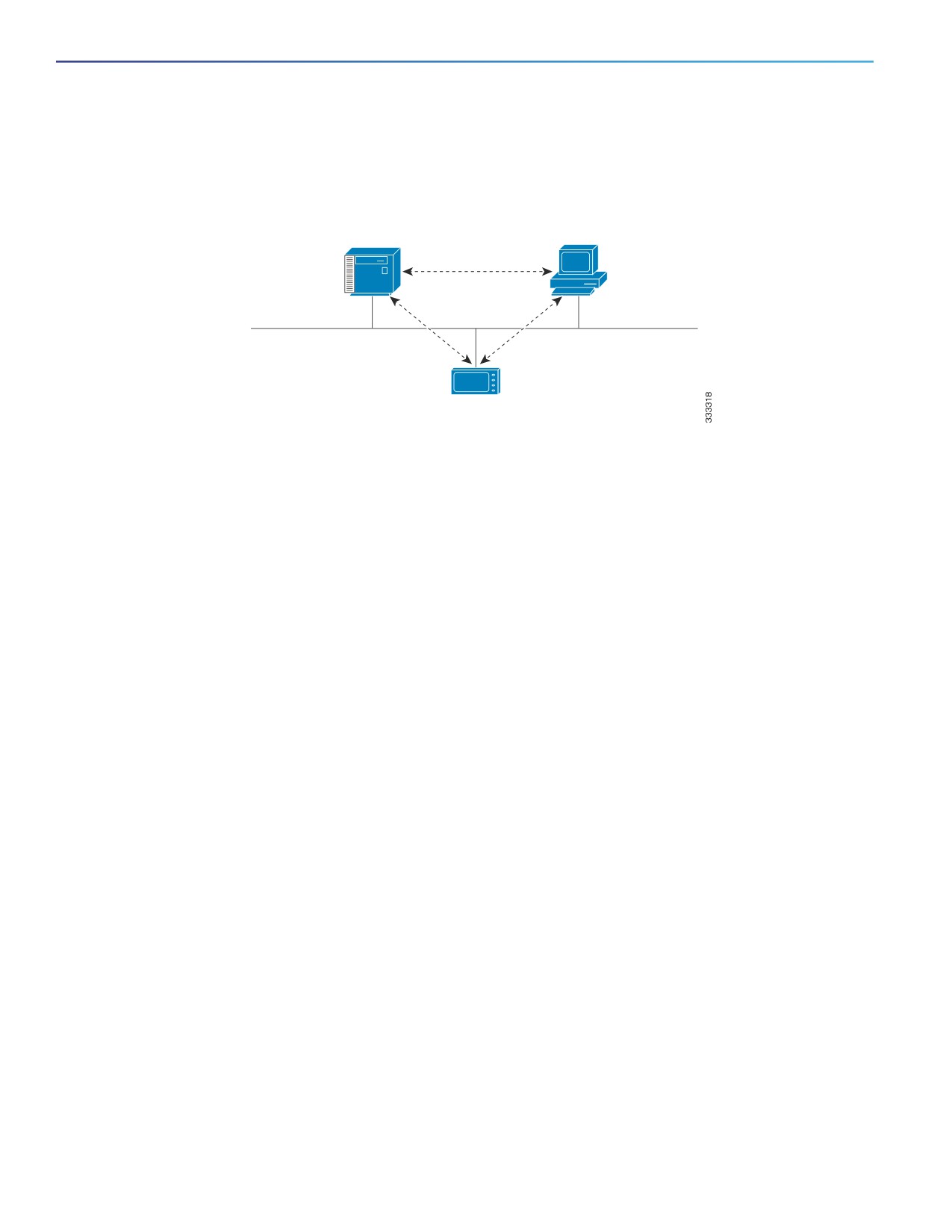
Figure 15
PROFINET Device Roles
I/O supervisor
I/O controller/PLC
(Programming device/PC)
Control and exchange
Commissioning,
data with I/O devices
Plant diagnostics
Ethernet
Read and write
I/O data
I/O device
(Field device)
An I/O controller is a programmable logic controller (PLC) that controls I/O devices and exchanges data such as
configuration, alarms, and I/O data through an automation program. The I/O controller and the I/O supervisor exchange
diagnostic information. The I/O controller shares configuration and input/output information with the I/O device and
receives alarms from the I/O device.
PROFINET is designed to be the sole or primary management system platform. Because the I/O controller detects the
switch with the Discovery and Configuration Protocol (DCP), and sets the device name and IP address, you do not need
to enter Cisco IOS commands for the basic configuration. For advanced configurations (for example, QoS, DHCP, and
similar features) you must use Cisco IOS commands on the switch because these features cannot be configured by using
PROFINET.
An I/O supervisor is an engineering station, such as a human machine interface (HMI) or PC, used for commissioning,
monitoring, and diagnostic analysis. The I/O supervisor exchanges diagnostic, status, control, and parameter information
with the I/O device.
An I/O device is a distributed input/output device such as a sensor, an actuator, or a motion controller.
Note: If Profinet DCP cannot detect the switch/PLC/IO mac addresses, temporarily disable the firewall/virus scan from
the Window PC that installed the Siemens STEP7 or TIA Portal.
In a PROFINET I/O system, all the I/O devices communicate over an Ethernet communication network to meet the
automation industry requirement for bus cycle times of less than 100 ms. The network uses switches and full-duplex
data exchange to avoid data collisions.
PROFINET Device Data Exchange
After PROFINET uses DCP to discover devices, including the switch, they establish application relationships (ARs) and
communication relationships (CRs). After a connection is established and information about device parameters is
exchanged, input and output data is exchanged. The switch uses non-real-time CRs to exchange the data attributes
listed in Table 17 on page 129 and Table 18 on page 129.
128

Configuring PROFINET
Information About Configuring PROFINET
Table 17
PROFINET I/O Switch Attributes
PROFINET I/O Switch Configuration
Value or Action
Attributes
Device name
Configures a name for the device.
TCP/IP
IP address, subnet mask, default gateway, SVI.
Primary temperature alarm
Enables or disables monitoring for the specified alarm.
Secondary temperature alarm
Enables or disables monitoring for the specified alarm.
RPS failed alarm
Enables or disables monitoring for the specified alarm.
Relay major alarm
Enables or disables monitoring for the specified alarm.
Reset to factory defaults
Uses the PROFINET I/O controller to reset the switch to factory defaults.
This action removes the startup configuration and reloads the switch.
Relay major configuration
Specifies the type of port alarm (for example, link fault) that triggers the
major relay. Any port configured with the specified alarm type can trigger
the major relay.
Table 18
PROFINET I/O Port Attributes
PROFINET I/O Port Configuration
Value or Action
Attributes
Speed
10/100/1000/auto,
Duplex
Half/full/auto,
Port mode
Access/trunk,
Link status
Shut down/no shut down,
Configure rate limiting
Broadcast, unicast, multicast threshold exceeds configured levels.
Port link fault alarm
Enables or disables monitoring for specified alarm.
Port not forwarding alarm
Enables or disables monitoring for specified alarm.
Port not operating alarm
Enables or disables monitoring for specified alarm.
Port FCS threshold alarm
Enables or disables monitoring for specified alarm.
PROFINET devices are integrated by using a general station description (GSD) file that contains the data for engineering
and data exchange between the I/O controller, the I/O supervisor, and the I/O devices, including the switch. Each
PROFINET I/O field device must have an associated GSD file that describes the properties of the device and contains all
this information required for configuration:
Device identification information (device ID, vendor ID and name, product family, number of ports)
Number and types of pluggable modules
Error text for diagnostic information
Communication parameters for I/O devices, including the minimum cycle time, the reduction ratio, and the watch
dog time
Configuration data for the I/O device modules, including speed, duplex, VLAN, port security information, alarms, and
broadcast-rate-limiting thresholds
Parameters configured for I/O device modules for the attributes listed in Table 18 on page 129
129

Configuring PROFINET
How to Configure PROFINET
The GSD file is on the switch, but the I/O supervisor uses this file.
Note: You must use the GSD file that is associated with the Cisco IOS release on the switch to manage your PROFINET
network. Both the I/O supervisor and the Cisco IOS software alert you to a mismatch between the GSD file and the switch
Cisco IOS software version.
How to Configure PROFINET
Configuring PROFINET
You can use either the PROFINET software on the I/O supervisor or the Cisco IOS software for basic switch configuration.
After you enable PROFINET, LLDP is automatically enabled on the switch because PROFINET relies on LLDP to fully
function. If you disable PROFINET, you can enable or disable LLDP as needed.
Default Configuration
PROFINET is enabled by default on all the base switch module ports. The default config is enabled on VLAN 1 but can
be changed to another VLAN ID. If PROFINET has been disabled, follow the instructions in the Enabling PROFINET,
page 130.
Enabling PROFINET
Command
Purpose
1.
configure terminal
Enters global configuration mode.
2.
profinet
Enables PROFINET on the switch.
3.
profinet id line
(Optional) Sets the PROFINET device identifier (ID) by using the Cisco IOS
software.
The maximum length is 240 characters. The only special characters allowed are
the period (.) and hyphen (-), and they are allowed only in specific positions
within the ID string. It can have multiple labels within the string. Each label can
be from 1 to 63 characters, and labels must be separated by a period (.). The
final character in the string must not be zero (0).
For more details about configuring the PROFINET ID, see the PROFINET
specification, document number TC2-06-0007a, filename
PN-AL-protocol_2722_V22_Oct07, available from PROFIBUS.
4.
profinet vlan vlan id
(Optional) Changes the VLAN number. The default VLAN number is 1. The VLAN
ID range is 1-4096. Supports one VLAN per switch.
5.
end
Returns to privileged EXEC mode.
6.
show running-config
Verifies your entries.
7.
copy running-config
(Optional) Saves your entries in the configuration file.
startup-config
130

Configuring PROFINET
Monitoring and Maintaining PROFINET
Monitoring and Maintaining PROFINET
Table 19
Commands for Displaying the PROFINET Configuration
Command
Purpose
show profinet sessions
Displays the currently connected PROFINET sessions.
show profinet status
Displays the status of the PROFINET subsystem.
show lldp neighbor interface x/x detail
Displays information about the adjacent interface.
Example
IE5000#show profinet status
State : Enabled
Vlan : 2
Id : Ie5000
Connected : Yes
ReductRatio : 128
GSD Version: Match
Troubleshooting PROFINET
The PLC has LEDs that display red for alarms, and the I/O supervisor software monitors those alarms.
To troubleshoot PROFINET use the debug profinet privileged EXEC command with the keywords shown in Table 20 on
page 131. Be aware that the output of a debug command might cause a serial link to fail. You should use these
commands only under the guidance of a Cisco Technical Support engineer. When you use this command, use Telnet to
access the Cisco IOS command-line interface (CLI) by using Ethernet rather than a serial port.
Table 20
Commands for Troubleshooting the PROFINET Configuration
Command
Purpose
debug profinet alarm
Displays the alarm status (on or off) and content of PROFINET alarms.
debug profinet cyclic
Displays information about the time-cycle-based PROFINET Ethernet frames.
debug profinet error
Displays the PROFINET session errors.
debug profinet packet ethernet
Displays information about the PROFINET Ethernet packets.
debug profinet packet udp
Displays information about the PROFINET Upper Layer Data Protocol (UDP)
packets.
debug profinet platform
Displays information about the interaction between the Cisco IOS software and
PROFINET.
debug profinet topology
Displays the PROFINET topology packets received.
debug profinet trace
Displays a group of traced debug output logs.
Additional References
The following sections provide references related to switch administration:
131

Configuring PROFINET
Additional References
Related Documents
Related Topic
Document Title
Cisco IOS basic commands
Cisco IOS Configuration Fundamentals Command Reference
Standards
Standards
Title
No new or modified standards are supported by this
—
feature, and support for existing standards has not
been modified by this feature.
MIBs
MIBs
MIBs Link
—
To locate and download MIBs using Cisco IOS XR software, use the
Cisco MIB Locator found at the following URL and choose a platform
under the Cisco Access Products menu:
RFCs
RFCs
Title
No new or modified RFCs are supported by this
—
feature, and support for existing RFCs has not been
modified by this feature.
Technical Assistance
Description
Link
The Cisco Technical Support website contains
thousands of pages of searchable technical content,
including links to products, technologies, solutions,
technical tips, and tools. Registered Cisco.com users
can log in from this page to access even more content.
132

Configuring CIP
Restrictions for Configuring CIP
CIP can be enabled on only one VLAN on the switch.
Information About Configuring CIP
The Common Industrial Protocol (CIP) is an industrial protocol for industrial automation applications. It is supported by
Open DeviceNet Vendors Association (ODVA), an organization that supports network technologies based upon CIP such
as DeviceNet, EtherNet/IP, CIP Safety and CIP Sync.
Previously known as Control and Information Protocol, CIP encompasses a comprehensive suite of messages and
services for the collection of manufacturing automation applications - control, safety, synchronization, motion,
configuration and information. CIP allows users to integrate these manufacturing applications with enterprise-level
Ethernet networks and the Internet.
How to Configure CIP
Default Configuration
By default, CIP is not enabled.
Enabling CIP
Command
Purpose
1.
configure terminal
Enters global configuration mode.
2.
cip security {password
Sets CIP security options on the switch.
password | window timeout
value}
3.
interface vlan 20
Enters interface configuration mode.
4.
cip enable
Enables CIP on a VLAN.
5.
end
Returns to privileged EXEC mode.
6.
show running-config
Verifies your entries.
7.
copy running-config
(Optional) Saves your entries in the configuration file.
startup-config
133
Configuring CIP
Monitoring CIP
Monitoring CIP
Table 21
Commands for Displaying the CIP Configuration
Command
Purpose
show cip {connection | faults | file |
Displays information about the CIP subsystem.
miscellaneous | object | security| session
| status}
Troubleshooting CIP
Table 22
Commands for Troubleshooting the CIP Configuration
Command
Purpose
debug cip {assembly | connection
Enables debugging of the CIP subsystem.
manager | errors | event | file | io | packet
| request response | security | session |
socket}
Additional References
The following sections provide references related to switch administration:
134

Configuring CIP
Additional References
Related Documents
Related Topic
Document Title
Cisco IOS basic commands
Cisco IOS Configuration Fundamentals Command Reference
Standards
Standards
Title
No new or modified standards are supported by this
—
feature, and support for existing standards has not
been modified by this feature.
MIBs
MIBs
MIBs Link
—
To locate and download MIBs using Cisco IOS XR software, use the
Cisco MIB Locator found at the following URL and choose a platform
under the Cisco Access Products menu:
RFCs
RFCs
Title
No new or modified RFCs are supported by this
—
feature, and support for existing RFCs has not been
modified by this feature.
Technical Assistance
Description
Link
The Cisco Technical Support website contains
thousands of pages of searchable technical content,
including links to products, technologies, solutions,
technical tips, and tools. Registered Cisco.com users
can log in from this page to access even more content.
135
Configuring CIP
Additional References
136
Configuring SDM Templates
Prerequisites for Configuring SDM Templates
You must enter the reload privileged EXEC command to have your configured SDM template take effect.
Restrictions for Configuring SDM Templates
When you select and configure SDM templates, you must reload the switch for the configuration to take effect.
If you try to configure IPv6 features without first selecting a dual IPv4 and IPv6 template, a warning message is
generated.
Using the dual-stack templates results in less TCAM capacity allowed for each resource, so do not use if you plan
to forward only IPv4 traffic.
Information About Configuring SDM Templates
SDM Templates
You can use SDM templates to configure system resources in the switch to optimize support for specific features,
depending on how the switch is used in the network.
You can select a template to provide maximum system usage for some functions or use the default template to balance
resources.
To allocate ternary content addressable memory (TCAM) resources for different usages, the switch SDM templates
prioritize system resources to optimize support for certain features. When running the IPservices license, you can select
SDM templates to optimize these features:
Default—The default template gives balance to all Layer 2 functions.
Dual IPv4 and IPv6—Allows the switch to be used in dual-stack environments (supporting both IPv4 and IPv6).
Routing—The routing template maximizes system resources for IPv4 unicast routing, typically required for a router or
aggregator in the center of a network.
See Dual IPv4 and IPv6 SDM Default Template, page 138.
There are four templates for ip services and one template for lanbase licensing.
137

Configuring SDM Templates
Information About Configuring SDM Templates
Table 23
IP Services license SDM Templates
Resource
Default
IPv4 Routing
Dual-Default
Dual-Routing
Unicast MAC addresses
16 K
16 K
16 K
16 K
IPv4 IGMP or IPv6 groups
1K IPv4
1K IPv4
1K IPv4
1K IPv4
1K IPv6
1K IPv6
Direct routes
16K IPv4
16K IPv4
4K IPv4
4K IPv4
4K IPv6
4K IPv6
Indirect routes
2K IPv4
8K IPv4
1.25K IPv4
2K IPv4
1.25K IPv6
3K IPv6
IPv4 or IPv6 policy-based routing ACEs
0.125K (IPv4
0.5K (IPv4
0.25K (IPv4 PBR)
0.125K (IPv4 PBR)
PBR)
PBR)
0.25K (IPv6 PBR)
0.125K (IPv6 PBR)
IPv4 or IPv6 QoSACEs
1.875K (IPv4
0.5K (IPv4
0.5K (IPv4 QoS)
0.5K (IPv4 QoS)
QoS)
QoS)
0.375K (IPv6
0.125K (IPv6
QoS)
QoS)
IPv4 or IPv6 port or MAC security ACEs
1.875K (IPv4
1K (IPv4
0.75K (IPv4 ACL)
0.625K (IPv4 ACL)
ACL)
ACL)
0.375K (IPv6 ACL)
0.125K (IPv6 ACL)
Table 24
Lanbase license SDM Template
Resource
Default
Unicast MAC addresses
16 K
IPv4 IGMP or IPv6 groups
1K IPv4/1K IPv6
Direct routes
4K IPv4/4K IPv6
Indirect routes
1.25K IPv4/1.25K IPv6
IPv4 or IPv6 policy-based routing ACEs
0.25K (IPv4 PBR)/0.25K (IPv6 PBR)
IPv4 or IPv6 QoSACEs
1K (IPv4 QoS)/0.25K (IPv6 QoS)
IPv4 or IPv6 port or MAC security ACEs
1K (IPv4 ACL)/0.25K (IPv6 ACL)
The first eight rows in the tables (unicast MAC addresses through security ACEs) represent approximate hardware
boundaries set when a template is selected. If a section of a hardware resource is full, all processing overflow is sent to
the CPU, seriously impacting switch performance.
Dual IPv4 and IPv6 SDM Default Template
You can select an SDM template to support IP Version 6 (IPv6) switching. The dual IPv4 and IPv6 template allows the
switch to be used in dual-stack environments (supporting both IPv4 and IPv6). Using the dual-stack templates results in
less TCAM capacity allowed for each resource. You should not use this template if you plan to forward only IPv4 traffic.
These SDM templates support IPv4 and IPv6 environments:
Dual IPv4 and IPv6 default template—Supports Layer 2, QoS, and ACLs for IPv4; and Layer 2, IPv6 host, and ACLs
for IPv6.
Dual IPv4 and IPv6 routing template—Supports Layer 2, multicast, routing (including policy-based routing), QoS, and
ACLs for IPv4; and Layer 2, routing, and ACLs for IPv6.
138

Configuring SDM Templates
How to Configure the Switch SDM Templates
How to Configure the Switch SDM Templates
Setting the SDM Template
Command
Purpose
1.
configure terminal
Enters global configuration mode.
2.
sdm prefer {default | dual-ipv4-and-ipv6
Specifies the SDM template to be used on the switch:
{default} | routing}
default—Gives balance to all functions.
dual-ipv4-and-ipv6—Selects a template that supports both
IPv4 and IPv6 routing.
— default—Balances IPv4 and IPv6 Layer 2 functionality.
routing—Maximizes IPv4 routing on the switch.
Use the no sdm prefer command to set the switch to the default
template. The default template balances the use of system
resources.
3.
end
Returns to privileged EXEC mode.
4.
reload
Reloads the operating system.
Configuration Examples for Configuring SDM Templates
Configuring IP Services Templates: Examples
This is an example of output from the show sdm prefer default command:
Switch# show sdm prefer default
"IPv4 default" template:
The selected template optimizes the resources in
the switch to support this level of features for
8 routed interfaces and 1024 VLANs.
number of unicast mac addresses:
16K
number of IPv4 IGMP groups + multicast routes:
1K
number of IPv4 unicast routes:
18K
number of directly-connected IPv4 hosts:
16K
number of indirect IPv4 routes:
2K
number of IPv6 multicast groups:
0
number of IPv6 unicast routes:
0
number of directly-connected IPv6 addresses:
0
number of indirect IPv6 unicast routes:
0
number of IPv4 policy based routing aces:
0.125k
number of IPv4/MAC qos aces:
1.875k
number of IPv4/MAC security aces:
1.875k
number of IPv6 policy based routing aces:
0
number of IPv6 qos aces:
0
number of IPv6 security aces:
0
This is an example of output from the show sdm prefer dual-ipv4-and-ipv6 default command:
139
Configuring SDM Templates
Configuration Examples for Configuring SDM Templates
Switch# show sdm prefer dual-ipv4-and-ipv6 default
"dual IPv4/IPv6 default" template:
The selected template optimizes the resources in
the switch to support this level of features for
8 routed interfaces and 1024 VLANs.
number of unicast mac addresses:
16K
number of IPv4 IGMP groups + multicast routes:
1K
number of IPv4 unicast routes:
5.25K
number of directly-connected IPv4 hosts:
4K
number of indirect IPv4 routes:
1.25K
number of IPv6 multicast groups:
1K
number of IPv6 unicast routes:
5.25K
number of directly-connected IPv6 addresses:
4K
number of indirect IPv6 unicast routes:
1.25K
number of IPv4 policy based routing aces:
0.25K
number of IPv4/MAC qos aces:
0.5K
number of IPv4/MAC security aces:
0.75K
number of IPv6 policy based routing aces:
0.25K
number of IPv6 qos aces:
0.375k
number of IPv6 security aces:
0.375k
This is an example of output from the show sdm prefer dual-ipv4-and-ipv6 routing command:
Switch# show sdm prefer dual-ipv4-and-ipv6 routing
"dual IPv4/IPv6 routing" template:
The selected template optimizes the resources in
the switch to support this level of features for
8 routed interfaces and 1024 VLANs.
number of unicast mac addresses:
16K
number of IPv4 IGMP groups + multicast routes:
1K
number of IPv4 unicast routes:
6K
number of directly-connected IPv4 hosts:
4K
number of indirect IPv4 routes:
2K
number of IPv6 multicast groups:
1K
number of IPv6 unicast routes:
7K
number of directly-connected IPv6 addresses:
4K
number of indirect IPv6 unicast routes:
3K
number of IPv4 policy based routing aces:
0.125k
number of IPv4/MAC qos aces:
0.5K
number of IPv4/MAC security aces:
0.625k
number of IPv6 policy based routing aces:
0.125k
number of IPv6 qos aces:
0.125k
number of IPv6 security aces:
0.125k
This is an example of output from the show sdm prefer routing command:
Switch# show sdm prefer routing
"IPv4 routing" template:
The selected template optimizes the resources in
the switch to support this level of features for
8 routed interfaces and 1024 VLANs.
number of unicast mac addresses:
16K
number of IPv4 IGMP groups + multicast routes:
1K
number of IPv4 unicast routes:
24K
number of directly-connected IPv4 hosts:
16K
number of indirect IPv4 routes:
8K
number of IPv6 multicast groups:
0
number of IPv6 unicast routes:
0
number of directly-connected IPv6 addresses:
0
number of indirect IPv6 unicast routes:
0
number of IPv4 policy based routing aces:
0.375k
140
Configuring SDM Templates
Configuration Examples for Configuring SDM Templates
number of IPv4/MAC qos aces:
0.5K
number of IPv4/MAC security aces:
1K
number of IPv6 policy based routing aces:
0
number of IPv6 qos aces:
0
number of IPv6 security aces:
0
Configuring Lanbase Templates: Example
This is an example of output from the show sdm prefer command on a Lanbase image:
Switch# show sdm prefer
The current template is "IPv4 default" template.
The selected template optimizes the resources in
the switch to support this level of features for
8 routed interfaces and 1024 VLANs.
number of unicast mac addresses:
16K
number of IPv4 IGMP groups + multicast routes:
1K
number of IPv4 unicast routes:
5.25K
number of directly-connected IPv4 hosts:
4K
number of indirect IPv4 routes:
1.25K
number of IPv6 multicast groups:
1K
number of IPv6 unicast routes:
5.25K
number of directly-connected IPv6 addresses:
4K
number of indirect IPv6 unicast routes:
1.25K
number of IPv4 policy based routing aces:
0.25K
number of IPv4/MAC qos aces:
1K
number of IPv4/MAC security aces:
1K
number of IPv6 policy based routing aces:
0.25K
number of IPv6 qos aces:
0.25K
number of IPv6 security aces:
0.25K
141
Configuring SDM Templates
Configuration Examples for Configuring SDM Templates
142
Configuring Switch-Based Authentication
Prerequisites for Configuring Switch-Based Authentication
If you configure an SDM template and then perform the show sdm prefer command, the template currently in use
displays.
You must enter the reload privileged EXEC command to have your configured SDM template take effect.
You should have access to and should configure a RADIUS server before configuring RADIUS features on your
switch.
At a minimum, you must identify the host or hosts that run the RADIUS server software and define the method lists
for RADIUS authentication. You can optionally define method lists for RADIUS authorization and accounting.
Restrictions for Configuring Switch-Based Authentication
To use the Radius CoA interface, a session must already exist on the switch. CoA can be used to identify a session
and enforce a disconnect request. The update affects only the specified session.
To use Secure Shell, you must install the cryptographic (encrypted) software image on your switch. You must obtain
authorization to use this feature and to download the cryptographic software files from Cisco.com. For more
information, see the release notes for this release.
Information About Configuring Switch-Based Authentication
Prevention for Unauthorized Switch Access
You can prevent unauthorized users from reconfiguring your switch and viewing configuration information. Typically, you
want network administrators to have access to your switch while you restrict access to users who dial from outside the
network through an asynchronous port, connect from outside the network through a serial port, or connect through a
terminal or workstation from within the local network.
To prevent unauthorized access into your switch, you should configure one or more of these security features:
At a minimum, you should configure passwords and privileges at each switch port. These passwords are locally
stored on the switch. When users attempt to access the switch through a port or line, they must enter the password
specified for the port or line before they can access the switch.
For an additional layer of security, you can also configure username and password pairs, which are locally stored on
the switch. These pairs are assigned to lines or ports and authenticate each user before that user can access the
switch. If you have defined privilege levels, you can also assign a specific privilege level (with associated rights and
privileges) to each username and password pair.
If you want to use username and password pairs, but you want to store them centrally on a server instead of locally,
you can store them in a database on a security server. Multiple networking devices can then use the same database
to obtain user authentication (and, if necessary, authorization) information.
143
Configuring Switch-Based Authentication
Information About Configuring Switch-Based Authentication
You can also enable the login enhancements feature, which logs both failed and unsuccessful login attempts. Login
enhancements can also be configured to block future login attempts after a set number of unsuccessful attempts
are made.
Password Protection
A simple way of providing terminal access control in your network is to use passwords and assign privilege levels.
Password protection restricts access to a network or network device. Privilege levels define what commands users can
enter after they have logged into a network device.
Default Password and Privilege Level Configuration
Table 25
Default Password and Privilege Levels
Feature
Default Setting
Enable password and privilege level
No password is defined. The default is level 15 (privileged EXEC level).
The password is not encrypted in the configuration file.
Enable secret password and privilege level
No password is defined. The default is level 15 (privileged EXEC level).
The password is encrypted before it is written to the configuration file.
Line password
No password is defined.
Enable Secret Passwords with Encryption
To provide an additional layer of security, particularly for passwords that cross the network or that are stored on a Trivial
File Transfer Protocol (TFTP) server, you can use either the enable password or enable secret global configuration
commands. Both commands accomplish the same thing; that is, you can establish an encrypted password that users
must enter to access privileged EXEC mode (the default) or any privilege level you specify.
We recommend that you use the enable secret command because it uses an improved encryption algorithm.
If you configure the enable secret command, it takes precedence over the enable password command; the two
commands cannot be in effect simultaneously.
Use the level keyword to define a password for a specific privilege level. After you specify the level and set a password,
give the password only to users who need to have access at this level. Use the privilege level global configuration
command to specify commands accessible at various levels.
If you enable password encryption, it applies to all passwords including username passwords, authentication key
passwords, the privileged command password, and console and virtual terminal line passwords.
To remove a password and level, use the no enable password [level level] or no enable secret [level level] global
configuration command. To disable password encryption, use the no service password-encryption global configuration
command.
Password Recovery
Any end user with physical access to the switch can recover from a lost password by interrupting the boot process while
the switch is powering on and manually deleting the configuration of the switch.
Press and hold the factory default button when power is applied to the switch. You can release the button once you see
the password-recovery mechanism is enabled message. You will be at the boot loader prompt at this point and will be
able to delete the configuration file (which contains the forgotten password).
144
Configuring Switch-Based Authentication
Information About Configuring Switch-Based Authentication
Telnet Password for a Terminal Line
When you power-up your switch for the first time, an automatic setup program runs to assign IP information and to create
a default configuration for continued use. The setup program also prompts you to configure your switch for Telnet access
through a password. If you did not configure this password during the setup program, you can configure it now through
the command-line interface (CLI).
Username and Password Pairs
You can configure username and password pairs, which are locally stored on the switch. These pairs are assigned to
lines or ports and authenticate each user before that user can access the switch. If you have defined privilege levels, you
can also assign a specific privilege level (with associated rights and privileges) to each username and password pair.
Multiple Privilege Levels
By default, the Cisco IOS software has two modes of password security: user EXEC and privileged EXEC. You can
configure up to 16 hierarchical levels of commands for each mode. By configuring multiple passwords, you can allow
different sets of users to have access to specified commands.
For example, if you want many users to have access to the clear line command, you can assign it level 2 security and
distribute the level 2 password fairly widely. But if you want more restricted access to the configure command, you can
assign it level 3 security and distribute that password to a more restricted group of users.
When you set a command to a privilege level, all commands whose syntax is a subset of that command are also set to
that level. For example, if you set the show ip traffic command to level 15, the show commands and show ip commands
are automatically set to privilege level 15 unless you set them individually to different levels.
To return to the default privilege for a given command, use the no privilege mode level level command global
configuration command.
Users can override the privilege level you set using the privilege level line configuration command by logging in to the
line and enabling a different privilege level. They can lower the privilege level by using the disable command. If users
know the password to a higher privilege level, they can use that password to enable the higher privilege level. You might
specify a high level or privilege level for your console line to restrict line usage.
To return to the default line privilege level, use the no privilege level line configuration command.
Switch Access with TACACS+
This section describes how to enable and configure Terminal Access Controller Access Control System Plus (TACACS+),
which provides detailed accounting information and flexible administrative control over authentication and authorization
processes. TACACS+ is facilitated through authentication, authorization, accounting (AAA) and can be enabled only
through AAA commands.
TACACS+
TACACS+ is a security application that provides centralized validation of users attempting to gain access to your switch.
TACACS+ services are maintained in a database on a TACACS+ daemon typically running on a UNIX or Windows NT
workstation. You should have access to and should configure a TACACS+ server before the configuring TACACS+
features on your switch.
TACACS+ provides for separate and modular authentication, authorization, and accounting facilities. TACACS+ allows
for a single access control server (the TACACS+ daemon) to provide each service—authentication, authorization, and
accounting—independently. Each service can be tied into its own database to take advantage of other services available
on that server or on the network, depending on the capabilities of the daemon.
145
Configuring Switch-Based Authentication
Information About Configuring Switch-Based Authentication
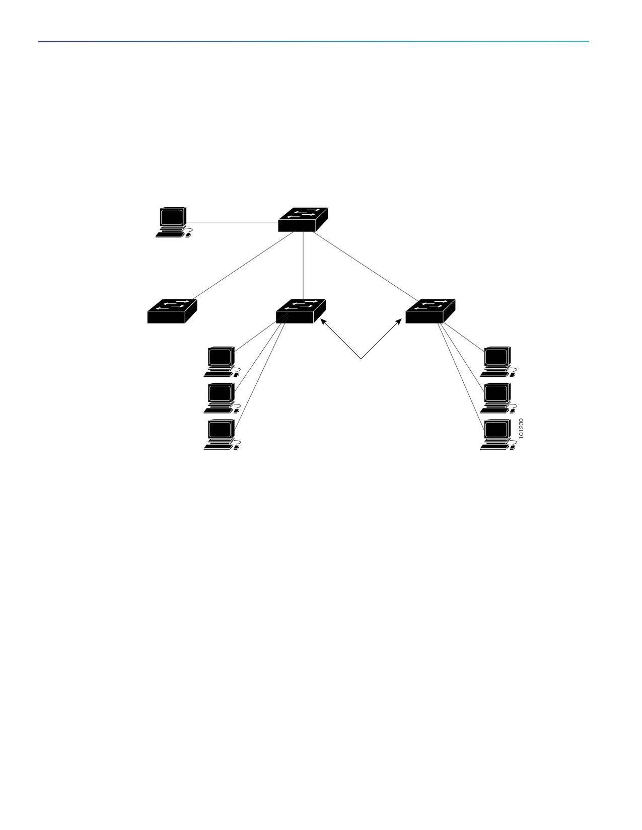
The goal of TACACS+ is to provide a method for managing multiple network access points from a single management
service. Your switch can be a network access server along with other Cisco routers and access servers. A network
access server provides connections to a single user, to a network or subnetwork, and to interconnected networks as
shown in Figure 16 on page 146.
Figure 16
Typical TACACS+ Network Configuration
UNIX workstation
(TACACS+
Catalyst 6500
server 1)
series switch
171.20.10.7
UNIX workstation
(TACACS+
server 2)
171.20.10.8
Configure the switches with the
TACACS+ server addresses.
Set an authentication key
(also configure the same key on
the TACACS+ servers).
Enable AAA.
Create a login authentication method list.
Apply the list to the terminal lines.
Create an authorization and accounting
Workstations
method list as required.
Workstations
TACACS+, administered through the AAA security services, can provide these services:
Authentication—Provides complete control of authentication through login and password dialog, challenge and
response, and messaging support.
The authentication facility can conduct a dialog with the user (for example, after a username and password are
provided, to challenge a user with several questions, such as home address, mother’s maiden name, service type,
and social security number). The TACACS+ authentication service can also send messages to user screens. For
example, a message could notify users that their passwords must be changed because of the company’s password
aging policy.
Authorization—Provides fine-grained control over user capabilities for the duration of the user’s session, including
but not limited to setting autocommands, access control, session duration, or protocol support. You can also enforce
restrictions on what commands a user can execute with the TACACS+ authorization feature.
Accounting—Collects and sends information used for billing, auditing, and reporting to the TACACS+ daemon.
Network managers can use the accounting facility to track user activity for a security audit or to provide information
for user billing. Accounting records include user identities, start and stop times, executed commands (such as PPP),
number of packets, and number of bytes.
The TACACS+ protocol provides authentication between the switch and the TACACS+ daemon, and it ensures
confidentiality because all protocol exchanges between the switch and the TACACS+ daemon are encrypted.
You need a system running the TACACS+ daemon software to use TACACS+ on your switch.
146
Configuring Switch-Based Authentication
Information About Configuring Switch-Based Authentication
TACACS+ Operation
When a user attempts a simple ASCII login by authenticating to a switch using TACACS+, this process occurs:
1.
When the connection is established, the switch contacts the TACACS+ daemon to obtain a username prompt to
show to the user. The user enters a username, and the switch then contacts the TACACS+ daemon to obtain a
password prompt. The switch displays the password prompt to the user, the user enters a password, and the
password is then sent to the TACACS+ daemon.
TACACS+ allows a dialog between the daemon and the user until the daemon receives enough information to
authenticate the user. The daemon prompts for a username and password combination, but can include other items,
such as the user’s mother’s maiden name.
2.
The switch eventually receives one of these responses from the TACACS+ daemon:
• ACCEPT—The user is authenticated and service can begin. If the switch is configured to require authorization,
authorization begins at this time.
• REJECT—The user is not authenticated. The user can be denied access or is prompted to retry the login
sequence, depending on the TACACS+ daemon.
• ERROR—An error occurred at some time during authentication with the daemon or in the network connection
between the daemon and the switch. If an ERROR response is received, the switch typically tries to use an
alternative method for authenticating the user.
• CONTINUE—The user is prompted for additional authentication information.
After authentication, the user undergoes an additional authorization phase if authorization has been enabled on the
switch. Users must first successfully complete TACACS+ authentication before proceeding to TACACS+
authorization.
3.
If TACACS+ authorization is required, the TACACS+ daemon is again contacted, and it returns an ACCEPT or REJECT
authorization response. If an ACCEPT response is returned, the response contains data in the form of attributes that
direct the EXEC or NETWORK session for that user and the services that the user can access:
• Telnet, Secure Shell (SSH), rlogin, or privileged EXEC services
• Connection parameters, including the host or client IP address, access list, and user timeouts
Default TACACS+ Configuration
TACACS+ and AAA are disabled by default.
To prevent a lapse in security, you cannot configure TACACS+ through a network management application. When
enabled, TACACS+ can authenticate users accessing the switch through the CLI.
Note: Although TACACS+ configuration is performed through the CLI, the TACACS+ server authenticates HTTP
connections that have been configured with a privilege level of 15.
TACACS+ Server Host and the Authentication Key
You can configure the switch to use a single server or AAA server groups to group existing server hosts for
authentication. You can group servers to select a subset of the configured server hosts and use them for a particular
service. The server group is used with a global server-host list and contains the list of IP addresses of the selected server
hosts.
147
Configuring Switch-Based Authentication
Information About Configuring Switch-Based Authentication
TACACS+ Login Authentication
To configure AAA authentication, you define a named list of authentication methods and then apply that list to various
ports. The method list defines the types of authentication to be performed and the sequence in which they are performed;
it must be applied to a specific port before any of the defined authentication methods are performed. The only exception
is the default method list (which, by coincidence, is named default). The default method list is automatically applied to
all ports except those that have a named method list explicitly defined. A defined method list overrides the default
method list.
A method list describes the sequence and authentication methods to be queried to authenticate a user. You can
designate one or more security protocols to be used for authentication, thus ensuring a backup system for authentication
in case the initial method fails. The software uses the first method listed to authenticate users; if that method fails to
respond, the software selects the next authentication method in the method list. This process continues until there is
successful communication with a listed authentication method or until all defined methods are exhausted. If
authentication fails at any point in this cycle—meaning that the security server or local username database responds by
denying the user access—the authentication process stops, and no other authentication methods are attempted.
TACACS+ Authorization for Privileged EXEC Access and Network Services
AAA authorization limits the services available to a user. When AAA authorization is enabled, the switch uses information
retrieved from the user’s profile, which is located either in the local user database or on the security server, to configure
the user’s session. The user is granted access to a requested service only if the information in the user profile allows it.
You can use the aaa authorization global configuration command with the tacacs+ keyword to set parameters that
restrict a user’s network access to privileged EXEC mode.
The aaa authorization exec tacacs+ local command sets these authorization parameters:
Use TACACS+ for privileged EXEC access authorization if authentication was performed by using TACACS+.
Use the local database if authentication was not performed by using TACACS+.
Note: Authorization is bypassed for authenticated users who log in through the CLI even if authorization has been
configured.
TACACS+ Accounting
The AAA accounting feature tracks the services that users are accessing and the amount of network resources that they
are consuming. When AAA accounting is enabled, the switch reports user activity to the TACACS+ security server in the
form of accounting records. Each accounting record contains accounting attribute-value (AV) pairs and is stored on the
security server. This data can then be analyzed for network management, client billing, or auditing.
Switch Access with RADIUS
This section describes how to enable and configure the RADIUS, which provides detailed accounting information and
flexible administrative control over authentication and authorization processes. RADIUS is facilitated through AAA and
can be enabled only through AAA commands.
RADIUS
RADIUS is a distributed client/server system that secures networks against unauthorized access. RADIUS clients run on
supported Cisco routers and switches. Clients send authentication requests to a central RADIUS server, which contains
all user authentication and network service access information. The RADIUS host is normally a multiuser system running
RADIUS server software from Cisco (Cisco Secure Access Control Server Version 3.0), Livingston, Merit, Microsoft, or
another software provider. For more information, see the RADIUS server documentation.
Use RADIUS in these network environments that require access security:
148
Configuring Switch-Based Authentication
Information About Configuring Switch-Based Authentication
Networks with multiple-vendor access servers, each supporting RADIUS. For example, access servers from several
vendors use a single RADIUS server-based security database. In an IP-based network with multiple vendors’ access
servers, dial-in users are authenticated through a RADIUS server that has been customized to work with the Kerberos
security system.
Turnkey network security environments in which applications support the RADIUS protocol, such as in an access
environment that uses a smart card access control system. In one case, RADIUS has been used with Enigma’s
security cards to validates users and to grant access to network resources.
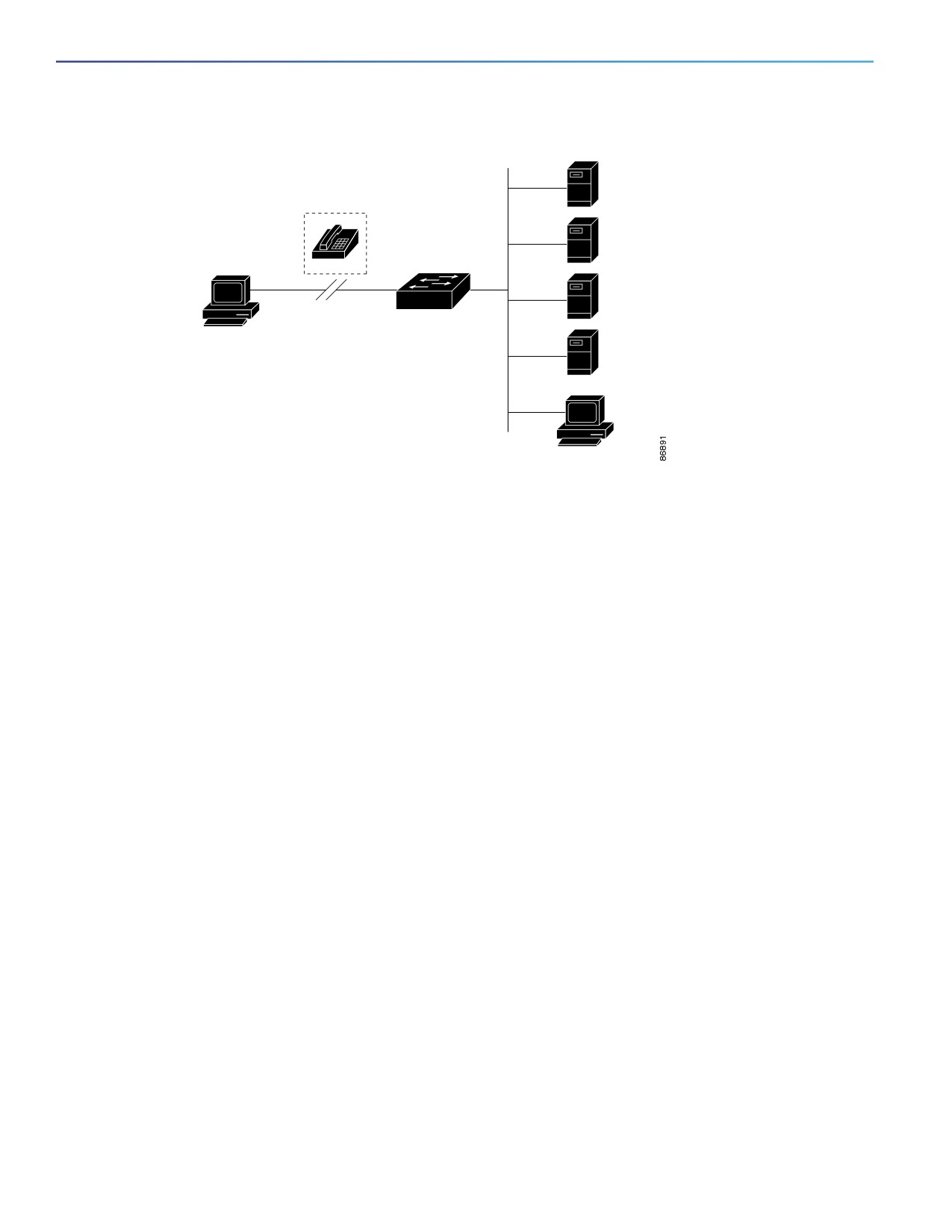
Networks already using RADIUS. You can add a Cisco switch containing a RADIUS client to the network. This might
be the first step when you make a transition to a TACACS+ server.
Network in which the user must only access a single service. Using RADIUS, you can control user access to a single
host, to a single utility such as Telnet, or to the network through a protocol such as IEEE 802.1x. For more information
about this protocol, see Configuring IEEE 802.1x Port-Based Authentication, page 189
Networks that require resource accounting. You can use RADIUS accounting independently of RADIUS
authentication or authorization. The RADIUS accounting functions allow data to be sent at the start and end of
services, showing the amount of resources (such as time, packets, bytes, and so forth) used during the session. An
Internet service provider might use a freeware-based version of RADIUS access control and accounting software to
meet special security and billing needs.
RADIUS is not suitable in these network security situations:
Multiprotocol access environments. RADIUS does not support AppleTalk Remote Access (ARA), NetBIOS Frame
Control Protocol (NBFCP), NetWare Asynchronous Services Interface (NASI), or X.25 PAD connections.
Switch-to-switch or router-to-router situations. RADIUS does not provide two-way authentication. RADIUS can be
used to authenticate from one device to a non-Cisco device if the non-Cisco device requires authentication.
Networks using a variety of services. RADIUS generally binds a user to one service model.
149
Configuring Switch-Based Authentication
Information About Configuring Switch-Based Authentication
Figure 17
Transitioning from RADIUS to TACACS+ Services
R1
RADIUS
server
R2
RADIUS
server
T1
TACACS+
server
Remote
T2
TACACS+
PC
server
Workstation
RADIUS Operation
When a user attempts to log in and authenticate to a switch that is access controlled by a RADIUS server, these events
occur:
1. The user is prompted to enter a username and password.
2. The username and encrypted password are sent over the network to the RADIUS server.
3. The user receives one of these responses from the RADIUS server:
a. ACCEPT—The user is authenticated.
b. REJECT—The user is either not authenticated and is prompted to re-enter the username and password, or access
is denied.
c. CHALLENGE—A challenge requires additional data from the user.
d. CHALLENGE PASSWORD—A response requests the user to select a new password.
The ACCEPT or REJECT response is bundled with additional data that is used for privileged EXEC or network
authorization. Users must first successfully complete RADIUS authentication before proceeding to RADIUS authorization,
if it is enabled. The additional data included with the ACCEPT or REJECT packets includes these items:
Telnet, SSH, rlogin, or privileged EXEC services
Connection parameters, including the host or client IP address, access list, and user timeouts
Default RADIUS Configuration
RADIUS and AAA are disabled by default.
To prevent a lapse in security, you cannot configure RADIUS through a network management application. When enabled,
RADIUS can authenticate users accessing the switch through the CLI.
RADIUS Change of Authorization
This section provides an overview of the RADIUS interface including available primitives and how they are used during a
Change of Authorization (CoA).
150
Configuring Switch-Based Authentication
Information About Configuring Switch-Based Authentication
Radius COA Overview
A standard RADIUS interface is typically used in a pulled model where the request originates from a network attached
device and the response come from the queried servers. Catalyst switches support the RADIUS Change of Authorization
(CoA) extensions defined in RFC 5176 that are typically used in a pushed model and allow for the dynamic reconfiguring
of sessions from external authentication, authorization, and accounting (AAA) or policy servers.
The switch supports these per-session CoA requests:
Session reauthentication
Session termination
Session termination with port shutdown
Session termination with port bounce
Change-of-Authorization Requests
Change of Authorization (CoA) requests, as described in RFC 5176, are used in a push model to allow for session
identification, host reauthentication, and session termination. The model is comprised of one request (CoA-Request) and
two possible response codes:
CoA acknowledgement (ACK) [CoA-ACK]
CoA non-acknowledgement (NAK) [CoA-NAK]
The request is initiated from a CoA client (typically a RADIUS or policy server) and directed to the switch that acts as a
listener.
RFC 5176 Compliance
The Disconnect Request message, which is also referred to as Packet of Disconnect (POD), is supported by the switch
for session termination.
151

Configuring Switch-Based Authentication
Information About Configuring Switch-Based Authentication
Attribute Number
Attribute Name
24
State
31
Calling-Station-ID
44
Acct-Session-ID
80
Message-Authenticator
101
Error-Cause
Value
Explanation
201
Residual Session Context Removed
202
Invalid EAP Packet (Ignored)
401
Unsupported Attribute
402
Missing Attribute
403
NAS Identification Mismatch
404
Invalid Request
405
Unsupported Service
406
Unsupported Extension
407
Invalid Attribute Value
501
Administratively Prohibited
502
Request Not Routable (Proxy)
503
Session Context Not Found
504
Session Context Not Removable
505
Other Proxy Processing Error
506
Resources Unavailable
507
Request Initiated
508
Multiple Session Selection Unsupported
CoA Request Response Code
The CoA Request response code can be used to convey a command to the switch. The supported commands are listed
in Table 26 on page 153.
CoA Session Identification
For disconnect and CoA requests targeted at a particular session, the switch locates the session based on one or more
of the following attributes:
Calling-Station-Id (IETF attribute 31 which contains the host MAC address)
Audit-Session-Id (Cisco VSA)
Acct-Session-Id (IETF attribute 44)
Unless all session identification attributes included in the CoA message match the session, the switch returns a
Disconnect-NAK or CoA-NAK with the Invalid Attribute Value error-code attribute.
For disconnect and CoA requests targeted to a particular session, any one of these session identifiers can be used:
Calling-Station-ID (IETF attribute 31, which should contain the MAC address)
152

Configuring Switch-Based Authentication
Information About Configuring Switch-Based Authentication
Audit-Session-ID (Cisco vendor-specific attribute)
Accounting-Session-ID (IETF attribute 44).
If more than one session identification attribute is included in the message, all the attributes must match the session or
the switch returns a Disconnect- negative acknowledgement (NAK) or CoA-NAK with the error code Invalid Attribute
Value.
The packet format for a CoA Request code as defined in RFC 5176 consists of the fields: Code, Identifier, Length,
Authenticator, and Attributes in Type:Length:Value (TLV) format.
0
1
2
3
0 1 2 3 4 5 6 7 8 9 0 1 2 3 4 5 6 7 8 9 0 1 2 3 4 5 6 7 8 9 0 1
+-+-+-+-+-+-+-+-+-+-+-+-+-+-+-+-+-+-+-+-+-+-+-+-+-+-+-+-+-+-+-+-+
|
Code
| Identifier
|
Length
|
+-+-+-+-+-+-+-+-+-+-+-+-+-+-+-+-+-+-+-+-+-+-+-+-+-+-+-+-+-+-+-+-+
|
|
|
Authenticator
|
|
|
|
|
+-+-+-+-+-+-+-+-+-+-+-+-+-+-+-+-+-+-+-+-+-+-+-+-+-+-+-+-+-+-+-+-+
| Attributes ...
+-+-+-+-+-+-+-+-+-+-+-+-+-
The attributes field is used to carry Cisco VSAs.
CoA ACK Response Code
If the authorization state is changed successfully, a positive acknowledgement (ACK) is sent. The attributes returned
within CoA ACK will vary based on the CoA Request and are discussed in individual CoA Commands.
CoA NAK Response Code
A negative acknowledgement (NAK) indicates a failure to change the authorization state and can include attributes that
indicate the reason for the failure. Use show commands to verify a successful CoA.
CoA Request Commands
Table 26
CoA Commands Supported on the Switch
Command1
Cisco VSA
Reauthenticate host
Cisco:Avpair=“subscriber:command=reauthenticate”
Terminate session
This is a standard disconnect request that does not require a VSA.
Bounce host port
Cisco:Avpair=“subscriber:command=bounce-host-port”
Disable host port
Cisco:Avpair=“subscriber:command=disable-host-port”
1. All CoA commands must include the session identifier between the switch and the CoA client.
CoA Session Reauthentication
The AAA server typically generates a session reauthentication request when a host with an unknown identity or posture
joins the network and is associated with a restricted access authorization profile (such as a guest VLAN). A
reauthentication request allows the host to be placed in the appropriate authorization group when its credentials are
known.
153
Configuring Switch-Based Authentication
Information About Configuring Switch-Based Authentication
To initiate session authentication, the AAA server sends a standard CoA-Request message which contains a Cisco
vendor-specific attribute (VSA) in this form: Cisco:Avpair=“subscriber:command=reauthenticate” and one or more
session identification attributes.
The current session state determines the switch response to the message. If the session is currently authenticated by
IEEE 802.1x, the switch responds by sending an Extensible Authentication Protocol over LAN (EAPoL) RequestId
message to the server.
If the session is currently authenticated by MAC authentication bypass (MAB), the switch sends an access-request to
the server, passing the same identity attributes used for the initial successful authentication.
If session authentication is in progress when the switch receives the command, the switch terminates the process, and
restarts the authentication sequence, starting with the method configured to be attempted first.
If the session is not yet authorized, or is authorized via guest VLAN, or critical VLAN, or similar policies, the
reauthentication message restarts the access control methods, beginning with the method configured to be attempted
first. The current authorization of the session is maintained until the reauthentication leads to a different authorization
result.
CoA Session Termination
There are three types of CoA requests that can trigger session termination. A CoA Disconnect-Request terminates the
session, without disabling the host port. This command causes reinitialization of the authenticator state machine for the
specified host, but does not restrict that host’s access to the network.
To restrict a host’s access to the network, use a CoA Request with the
Cisco:Avpair="subscriber:command=disable-host-port" VSA. This command is useful when a host is known to be
causing problems on the network, and you need to immediately block network access for the host. When you want to
restore network access on the port, reenable it using a non-RADIUS mechanism.
When a device with no supplicant, such as a printer, needs to acquire a new IP address (for example, after a VLAN
change), terminate the session on the host port with port-bounce (temporarily disable and then reenable the port).
CoA Disconnect-Request
This command is a standard Disconnect-Request. Because this command is session-oriented, it must be accompanied
by one or more of the session identification attributes described in the CoA Session Identification, page 152. If the
session cannot be located, the switch returns a Disconnect-NAK message with the “Session Context Not Found”
error-code attribute. If the session is located, the switch terminates the session. After the session has been completely
removed, the switch returns a Disconnect-ACK.
If the switch fails-over to a standby switch before returning a Disconnect-ACK to the client, the process is repeated on
the new active switch when the request is resent from the client. If the session is not found following resend, a
Disconnect-ACK is sent with the “Session Context Not Found” error-code attribute.
CoA Request: Disable Host Port
This command is carried in a standard CoA-Request message that has this new VSA:
Cisco:Avpair="subscriber:command=disable-host-port"
Because this command is session-oriented, it must be accompanied by one or more of the session identification
attributes described in the CoA Session Identification, page 152. If the session cannot be located, the switch returns a
CoA-NAK message with the “Session Context Not Found” error-code attribute. If the session is located, the switch
disables the hosting port and returns a CoA-ACK message.
If the switch fails before returning a CoA-ACK to the client, the process is repeated on the new active switch when the
request is resent from the client. If the switch fails after returning a CoA-ACK message to the client but before the
operation has completed, the operation is restarted on the new active switch.
154
Configuring Switch-Based Authentication
Information About Configuring Switch-Based Authentication
Note: A Disconnect-Request failure following command resend could be the result of either a successful session
termination before change-over (if the Disconnect-ACK was not sent) or a session termination by other means (for
example, a link failure) that occurred after the original command was issued and before the standby switch became
active.
CoA Request: Bounce-Port
This command is carried in a standard CoA-Request message that contains this VSA:
Cisco:Avpair="subscriber:command=bounce-host-port"
Because this command is session-oriented, it must be accompanied by one or more of the session identification
attributes described in the CoA Session Identification, page 152. If the session cannot be located, the switch returns a
CoA-NAK message with the “Session Context Not Found” error-code attribute. If the session is located, the switch
disables the hosting port for a period of 10 seconds, reenables it (port-bounce), and returns a CoA-ACK.
If the switch fails before returning a CoA-ACK to the client, the process is repeated on the new active switch when the
request is resent from the client. If the switch fails after returning a CoA-ACK message to the client but before the
operation has completed, the operation is restarted on the new active switch.
RADIUS Server Host
Switch-to-RADIUS-server communication involves several components:
Hostname or IP address
Authentication destination port
Accounting destination port
Key string
Timeout period
Retransmission value
You identify RADIUS security servers by their hostname or IP address, hostname and specific UDP port numbers, or their
IP address and specific UDP port numbers. The combination of the IP address and the UDP port number creates a unique
identifier, allowing different ports to be individually defined as RADIUS hosts providing a specific AAA service. This
unique identifier enables RADIUS requests to be sent to multiple UDP ports on a server at the same IP address.
If two different host entries on the same RADIUS server are configured for the same service—for example,
accounting—the second host entry configured acts as a fail-over backup to the first one. Using this example, if the first
host entry fails to provide accounting services, the %RADIUS-4-RADIUS_DEAD message appears, and then the switch tries
the second host entry configured on the same device for accounting services. (The RADIUS host entries are tried in the
order that they are configured.)
A RADIUS server and the switch use a shared secret text string to encrypt passwords and exchange responses. To
configure RADIUS to use the AAA security commands, you must specify the host running the RADIUS server daemon
and a secret text (key) string that it shares with the switch.
The timeout, retransmission, and encryption key values can be configured globally for all RADIUS servers, on a per-server
basis, or in some combination of global and per-server settings. To apply these settings globally to all RADIUS servers
communicating with the switch, use the three unique global configuration commands: radius-server timeout,
radius-server retransmit, and radius-server key. To apply these values on a specific RADIUS server, use the
radius-server host global configuration command.
155