Cisco Industrial Ethernet 4000, 4010 and 5000 Switch Software. Configuration Guide (2022) - page 5
Performing Switch Setup Configuration
Information About Performing Switch Setup Configuration
If the relay device is a Cisco router, enable IP routing (ip routing global configuration command), and configure helper
addresses by using the ip helper-address interface configuration command.
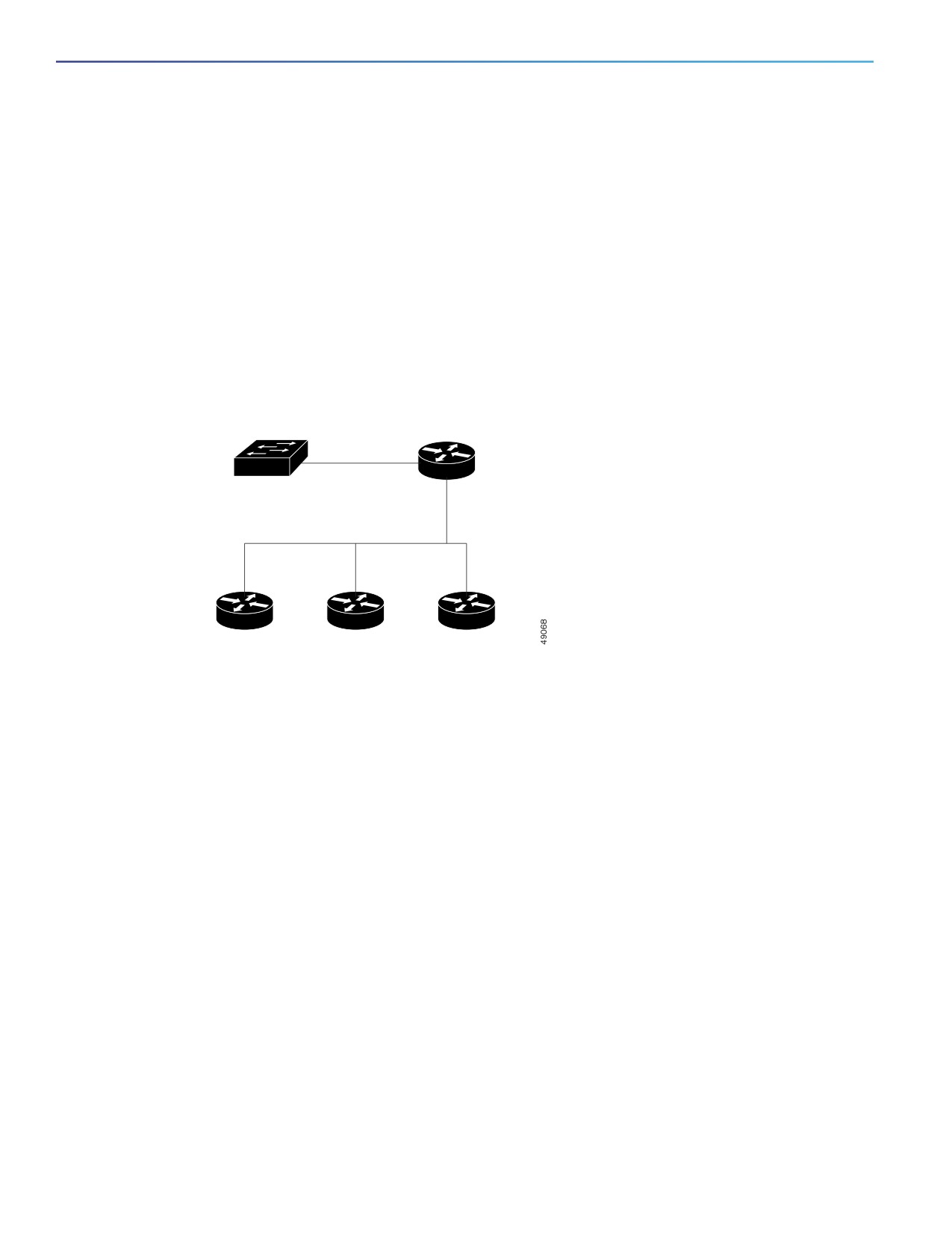
For example, in Figure 3 on page 66, configure the router interfaces as follows:
On interface 10.0.0.2:
router(config-if)# ip helper-address 20.0.0.2
router(config-if)# ip helper-address 20.0.0.3
router(config-if)# ip helper-address 20.0.0.4
On interface 20.0.0.1:
router(config-if)# ip helper-address 10.0.0.1
Figure 3
Relay Device Used in Autoconfiguration
Switch
Cisco router
(DHCP client)
(Relay)
10.0.0.2
10.0.0.1
20.0.0.1
20.0.0.2
20.0.0.3
20.0.0.4
DHCP server
TFTP server
DNS server
How to Obtain Configuration Files
Depending on the availability of the IP address and the configuration filename in the DHCP reserved lease, the switch
obtains its configuration information in these ways:
The IP address and the configuration filename is reserved for the switch and provided in the DHCP reply (one-file
read method).
The switch receives its IP address, subnet mask, TFTP server address, and the configuration filename from the DHCP
server. The switch sends a unicast message to the TFTP server to retrieve the named configuration file from the base
directory of the server and upon receipt, it completes its boot-up process.
The IP address and the configuration filename is reserved for the switch, but the TFTP server address is not provided
in the DHCP reply (one-file read method).
The switch receives its IP address, subnet mask, and the configuration filename from the DHCP server. The switch
sends a broadcast message to a TFTP server to retrieve the named configuration file from the base directory of the
server, and upon receipt, it completes its boot-up process.
Only the IP address is reserved for the switch and provided in the DHCP reply. The configuration filename is not
provided (two-file read method).
The switch receives its IP address, subnet mask, and the TFTP server address from the DHCP server. The switch
sends a unicast message to the TFTP server to retrieve the network-confg or cisconet.cfg default configuration file.
(If the network-confg file cannot be read, the switch reads the cisconet.cfg file.)
66
Performing Switch Setup Configuration
Information About Performing Switch Setup Configuration
The default configuration file contains the hostnames-to-IP-address mapping for the switch. The switch fills its host
table with the information in the file and obtains its hostname. If the hostname is not found in the file, the switch uses
the hostname in the DHCP reply. If the hostname is not specified in the DHCP reply, the switch uses the default
Switch as its hostname.
After obtaining its hostname from the default configuration file or the DHCP reply, the switch reads the configuration
file that has the same name as its hostname (hostname-confg or hostname.cfg, depending on whether
network-confg or cisconet.cfg was read earlier) from the TFTP server. If the cisconet.cfg file is read, the filename of
the host is truncated to eight characters.
If the switch cannot read the network-confg, cisconet.cfg, or the hostname file, it reads the router-confg file. If the
switch cannot read the router-confg file, it reads the ciscortr.cfg file.
Note: The switch broadcasts TFTP server requests if the TFTP server is not obtained from the DHCP replies, if all
attempts to read the configuration file through unicast transmissions fail, or if the TFTP server name cannot be resolved
to an IP address.
How to Control Environment Variables
With a normally operating switch, you enter the boot loader mode only through a switch console connection configured
for 9600 b/s. Unplug the switch power cord, and press the switch Mode button while reconnecting the power cord. You
can release the Mode button a second or two after the LED above port 1 turns off. Then the boot loader switch: prompt
appears.
The switch boot loader software provides support for nonvolatile environment variables, which can be used to control
how the boot loader or any other software running on the system behaves. Boot loader environment variables are similar
to environment variables that can be set on UNIX or DOS systems.
Environment variables that have values are stored in flash memory outside of the flash file system.
Each line in these files contains an environment variable name and an equal sign followed by the value of the variable. A
variable has no value if it is not listed in this file; it has a value if it is listed in the file even if the value is a null string. A
variable that is set to a null string (for example, “ ”) is a variable with a value. Many environment variables are predefined
and have default values.
Environment variables store two kinds of data:
Data that controls code, which does not read the Cisco IOS configuration file. For example, the name of a boot loader
helper file, which extends or patches the functionality of the boot loader can be stored as an environment variable.
Data that controls code, which is responsible for reading the Cisco IOS configuration file. For example, the name of
the Cisco IOS configuration file can be stored as an environment variable.
You can change the settings of the environment variables by accessing the boot loader or by using Cisco IOS commands.
Under normal circumstances, it is not necessary to alter the setting of the environment variables.
Common Environment Variables
Table 14 on page 68 describes the function of the most common environment variables.
67

Performing Switch Setup Configuration
Information About Performing Switch Setup Configuration
Table 14
Environment Variables
Variable
Boot Loader Command
Cisco IOS Global Configuration Command
BOOT
set BOOT filesystem:/file-url ...
boot system filesystem:/file-url ...
A semicolon-separated list of executable files to
Specifies the Cisco IOS image to load during the
try to load and execute when automatically
next boot cycle. This command changes the
booting. If the BOOT environment variable is not
setting of the BOOT environment variable.
set, the system attempts to load and execute the
first executable image it can find by using a
recursive, depth-first search through the flash
file system. If the BOOT variable is set but the
specified images cannot be loaded, the system
attempts to boot the first bootable file that it can
find in the flash file system.
MANUAL_BOOT
set MANUAL_BOOT yes
boot manual
Decides whether the switch automatically or
Enables manually booting up the switch during
manually boots up.
the next boot cycle and changes the setting of the
MANUAL_BOOT environment variable.
Valid values are 1, yes, 0, and no. If it is set to no
or 0, the boot loader attempts to automatically
The next time you reboot the system, the switch
boot up the system. If it is set to anything else,
is in boot loader mode. To boot up the system,
you must manually boot up the switch from the
use the boot flash:filesystem:/file-url boot loader
boot loader mode.
command, and specify the name of the bootable
image.
CONFIG_FILE
set CONFIG_FILE flash:/file-url
boot config-file flash:/file-url
Changes the filename that Cisco IOS uses to
Specifies the filename that Cisco IOS uses to read
read and write a nonvolatile copy of the system
and write a nonvolatile copy of the system
configuration.
configuration. This command changes the
CONFIG_FILE environment variable.
Scheduled Reload of the Software Image
You can schedule a reload of the software image to occur on the switch at a later time (for example, late at night or during
the weekend when the switch is used less), or you can synchronize a reload network-wide (for example, to perform a
software upgrade on all switches in the network).
Note: A scheduled reload must take place within approximately 24 days.
You have these reload options:
Software reload to take effect in the specified minutes or hours and minutes. The reload must take place within
approximately 24 days. You can specify the reason for the reload in a string up to 255 characters in length.
Software reload to take place at the specified time (using a 24-hour clock). If you specify the month and day, the
reload is scheduled to take place at the specified time and date. If you do not specify the month and day, the reload
takes place at the specified time on the current day (if the specified time is later than the current time) or on the next
day (if the specified time is earlier than the current time). Specifying 00:00 schedules the reload for midnight.
The reload command halts the system. If the system is not set to manually boot up, it reboots itself.
If your switch is configured for manual booting, do not reload it from a virtual terminal. This restriction prevents the switch
from entering the boot loader mode and thereby taking it from the remote user’s control.
68

Performing Switch Setup Configuration
How to Perform Switch Setup Configuration
If you modify your configuration file, the switch prompts you to save the configuration before reloading. During the save
operation, the system requests whether you want to proceed with the save if the CONFIG_FILE environment variable
points to a startup configuration file that no longer exists. If you proceed in this situation, the system enters setup mode
upon reload.
To cancel a previously scheduled reload, use the reload cancel privileged EXEC command.
How to Perform Switch Setup Configuration
Using DHCP to download a new image and a new configuration to a switch requires that you configure at least two
switches. One switch acts as a DHCP and TFTP server and the second switch (client) is configured to download either
a new configuration file or a new configuration file and a new image file.
Configuring DHCP Autoconfiguration (Only Configuration File)
This task describes how to configure DHCP autoconfiguration of the TFTP and DHCP settings on a new switch to
download a new configuration file.
Command
Purpose
1.
configure terminal
Enters global configuration mode.
2.
ip dhcp poolname
Creates a name for the DHCP Server address pool, and enters DHCP
pool configuration mode.
3.
bootfile filename
Specifies the name of the configuration file that is used as a boot
image.
4.
network network-number mask
Specifies the subnet network number and mask of the DHCP address
prefix-length
pool.
Note: The prefix length specifies the number of bits that comprise the
address prefix. The prefix is an alternative way of specifying the
network mask of the client. The prefix length must be preceded by a
forward slash (/).
5.
default-router address
Specifies the IP address of the default router for a DHCP client.
6.
option 150 address
Specifies the IP address of the TFTP server.
7.
exit
Returns to global configuration mode.
8.
tftp-server flash:filename.text
Specifies the configuration file on the TFTP server.
9.
interface interface-id
Specifies the address of the client that will receive the configuration
file.
10.
no switchport
Puts the interface into Layer 3 mode.
11.
ip address address mask
Specifies the IP address and mask for the interface.
12.
end
Returns to privileged EXEC mode.
13.
copy running-config startup-config
(Optional) Saves your entries in the configuration file.
Configuring DHCP Auto-Image Update (Configuration File and Image)
This task describes DHCP autoconfiguration to configure TFTP and DHCP settings on a new switch to download a new
image and a new configuration file.
69

Performing Switch Setup Configuration
How to Perform Switch Setup Configuration
Before You Begin
You must create a text file (for example, autoinstall_dhcp) that will be uploaded to the switch. In the text file, put the name
of the image that you want to download. This image must be a tar and not a bin file.
Command
Purpose
1.
configure terminal
Enters global configuration mode.
2.
ip dhcp pool name
Creates a name for the DHCP server address pool and enters DHCP pool
configuration mode.
3.
bootfile filename
Specifies the name of the file that is used as a boot image.
4.
network network-number mask
Specifies the subnet network number and mask of the DHCP address
prefix-length
pool.
Note: The prefix length specifies the number of bits that comprise the
address prefix. The prefix is an alternative way of specifying the network
mask of the client. The prefix length must be preceded by a forward slash
(/).
5.
default-router address
Specifies the IP address of the default router for a DHCP client.
6.
option 150 address
Specifies the IP address of the TFTP server.
7.
option 125 hex
Specifies the path to the text file that describes the path to the image file.
8.
copy tftp flash filename.txt
Uploads the text file to the switch.
9.
copy tftp flash imagename.tar
Uploads the tar file for the new image to the switch.
10.
exit
Returns to global configuration mode.
11.
tftp-server flash:config.text
Specifies the Cisco IOS configuration file on the TFTP server.
12.
tftp-server flash:imagename.tar
Specifies the image name on the TFTP server.
13.
tftp-server flash:filename.txt
Specifies the text file that contains the name of the image file to
download.
14.
interface interface-id
Specifies the address of the client that will receive the configuration file.
15.
no switchport
Puts the interface into Layer 3 mode.
16.
ip address address mask
Specifies the IP address and mask for the interface.
17.
end
Returns to privileged EXEC mode.
18.
copy running-config startup-config
(Optional) Saves your entries in the configuration file.
Configuring the Client
You should only configure and enable the Layer 3 interface. Do not assign an IP address or DHCP-based
autoconfiguration with a saved configuration.
Command
Purpose
1.
configure terminal
Enters global configuration mode.
2.
boot host dhcp
Enables autoconfiguration with a saved configuration.
3.
boot host retry timeout timeout-value
(Optional) Sets the amount of time the system tries to
download a configuration file.
Note: If you do not set a timeout, the system tries
indefinitely to obtain an IP address from the DHCP server.
70

Performing Switch Setup Configuration
How to Perform Switch Setup Configuration
Command
Purpose
4.
banner config-save ^C warning-message ^C
(Optional) Creates warning messages to be displayed
when you try to save the configuration file to NVRAM.
5.
end
Returns to privileged EXEC mode.
6.
show boot
Verifies the configuration.
Manually Assigning IP Information on a Routed Port
This task describes how to manually assign IP information on a Layer 3 routed port.
Command
Purpose
1.
configure terminal
Enters global configuration mode.
2.
interface type id
Enters interface configuration mode.
3.
no switchport
Configures an interface into Layer 3 mode.
4.
ip address address mask
Specifies the IP address and mask for the interface.
5.
exit
Returns to global configuration mode.
6.
ip default-gateway ip-address
Enters the IP address of the next-hop router interface that is directly
connected to the switch where a default gateway is being configured.
The default gateway receives IP packets with unresolved destination IP
addresses from the switch.
Once the default gateway is configured, the switch has connectivity to
the remote networks with which a host needs to communicate.
Note: When your switch is configured to route with IP, it does not need to
have a default gateway set.
7.
end
Returns to privileged EXEC mode.
8.
show ip redirects
Verifies the configured default gateway.
9.
copy running-config startup-config
(Optional) Saves your entries in the configuration file.
Manually Assigning IP Information to SVIs
This task describes how to manually assign IP information to multiple switched virtual interfaces (SVIs).
Command
Purpose
1.
configure terminal
Enters global configuration mode.
2.
interface vlan vlan-id
Enters interface configuration mode, and enters the VLAN to which the IP
information is assigned. The VLAN range is 1 to 4096.
3.
ip address ip-address subnet-mask
Enters the IP address and subnet mask.
4.
exit
Returns to global configuration mode.
71

Performing Switch Setup Configuration
How to Perform Switch Setup Configuration
Command
Purpose
5.
ip default-gateway ip-address
Enters the IP address of the next-hop router interface that is directly
connected to the switch where a default gateway is being configured.
The default gateway receives IP packets with unresolved destination IP
addresses from the switch.
Once the default gateway is configured, the switch has connectivity to
the remote networks with which a host needs to communicate.
Note: When your switch is configured to route with IP, it does not need to
have a default gateway set.
6.
end
Returns to privileged EXEC mode.
7.
show interfaces vlan vlan-id
Verifies the configured IP address.
8.
show ip redirects
Verifies the configured default gateway.
9.
copy running-config startup-config
(Optional) Saves your entries in the configuration file.
Modifying the Startup Configuration
Specifying the Filename to Read and Write the System Configuration
By default, the Cisco IOS software uses the config.text file to read and write a nonvolatile copy of the system
configuration. However, you can specify a different filename, which will be loaded during the next boot-up cycle.
Command
Purpose
1.
configure terminal
Enters global configuration mode.
2.
boot config-file flash:/file-url
Specifies the configuration file to load during the next boot-up
cycle.
For file-url, specify the path (directory) and the configuration
filename.
Filenames and directory names are case sensitive.
3.
end
Returns to privileged EXEC mode.
4.
show boot
Verifies your entries.
The boot config-file global configuration command changes the
setting of the CONFIG_FILE environment variable.
5.
copy running-config startup-config
(Optional) Saves your entries in the configuration file.
Manually Booting the Switch
By default, the switch automatically boots up; however, you can configure it to manually boot up.
Before You Begin
Use a standalone switch for this task.
72

Performing Switch Setup Configuration
How to Perform Switch Setup Configuration
Command
Purpose
1.
configure terminal
Enters global configuration mode.
2.
boot manual
Enables the switch to manually boot up during the next boot cycle.
3.
end
Returns to privileged EXEC mode.
4.
show boot
Verifies your entries.
The boot manual global command changes the setting of the
MANUAL_BOOT environment variable.
The next time you reboot the system, the switch is in boot loader
mode, shown by the switch: prompt. To boot up the system, use the
boot filesystem:/file-url boot loader command.
For filesystem:, use flash: for the system board flash device.
For file-url, specify the path (directory) and the name of the
bootable image.
Filenames and directory names are case sensitive.
5.
copy running-config startup-config
(Optional) Saves your entries in the configuration file.
Booting a Specific Software Image
By default, the switch attempts to automatically boot up the system using information in the BOOT environment variable.
If this variable is not set, the switch attempts to load and execute the first executable image it can by performing a
recursive, depth-first search throughout the flash file system. In a depth-first search of a directory, each encountered
subdirectory is completely searched before continuing the search in the original directory. However, you can specify a
specific image to boot up.
Command
Purpose
1.
configure terminal
Enters global configuration mode.
2.
boot system filesystem:/file-url
Configures the switch to boot a specific image in flash memory during the
next boot cycle.
For filesystem:, use flash: for the system board flash device.
For file-url, specify the path (directory) and the name of the bootable
image.
Filenames and directory names are case sensitive.
3.
end
Returns to privileged EXEC mode.
4.
show boot
Verifies your entries.
The boot system global command changes the setting of the BOOT
environment variable.
During the next boot cycle, the switch attempts to automatically boot up
the system using information in the BOOT environment variable.
5.
copy running-config startup-config
(Optional) Saves your entries in the configuration file.
73
Performing Switch Setup Configuration
Monitoring Switch Setup Configuration
Monitoring Switch Setup Configuration
Verifying the Switch Running Configuration
You can check the configuration settings that you entered or changes that you made by entering this privileged EXEC
command:
Switch# show running-config
Building configuration...
Current configuration: 1363 bytes
!
version 12.2
no service pad
service timestamps debug uptime
service timestamps log uptime
no service password-encryption
!
hostname Switch A
!
enable secret 5
$1$ej9.$DMUvAUnZOAmvmgqBEzIxE0
!
<output truncated>
interface GigabitEthernet1/17
no switchport
ip address 172.20.137.50 255.255.255.0
!
interface GigabitEthernet1/18
mvr type source
<output truncated>
...!
interface VLAN1
ip address 172.20.137.50 255.255.255.0
no ip directed-broadcast
!
ip default-gateway 172.20.137.1 !
!
snmp-server community private RW
snmp-server community public RO
snmp-server community private@es0 RW
snmp-server community public@es0 RO
snmp-server chassis-id 0x12
!
end
To store the configuration or changes you have made to your startup configuration in flash memory, enter this privileged
EXEC command:
Switch# copy running-config startup-config
Destination filename [startup-config]?
Building configuration...
This command saves the configuration settings that you made. If you fail to do this, your configuration will be lost the
next time you reload the system. To display information stored in the NVRAM section of flash memory, use the show
startup-config or more startup-config privileged EXEC command.
For more information about alternative locations from which to copy the configuration file, see Working with the Cisco
IOS File System, Configuration Files, and Software Images, page 1035
74
Performing Switch Setup Configuration
Configuration Examples for Performing Switch Setup Configuration
Configuration Examples for Performing Switch Setup
Configuration
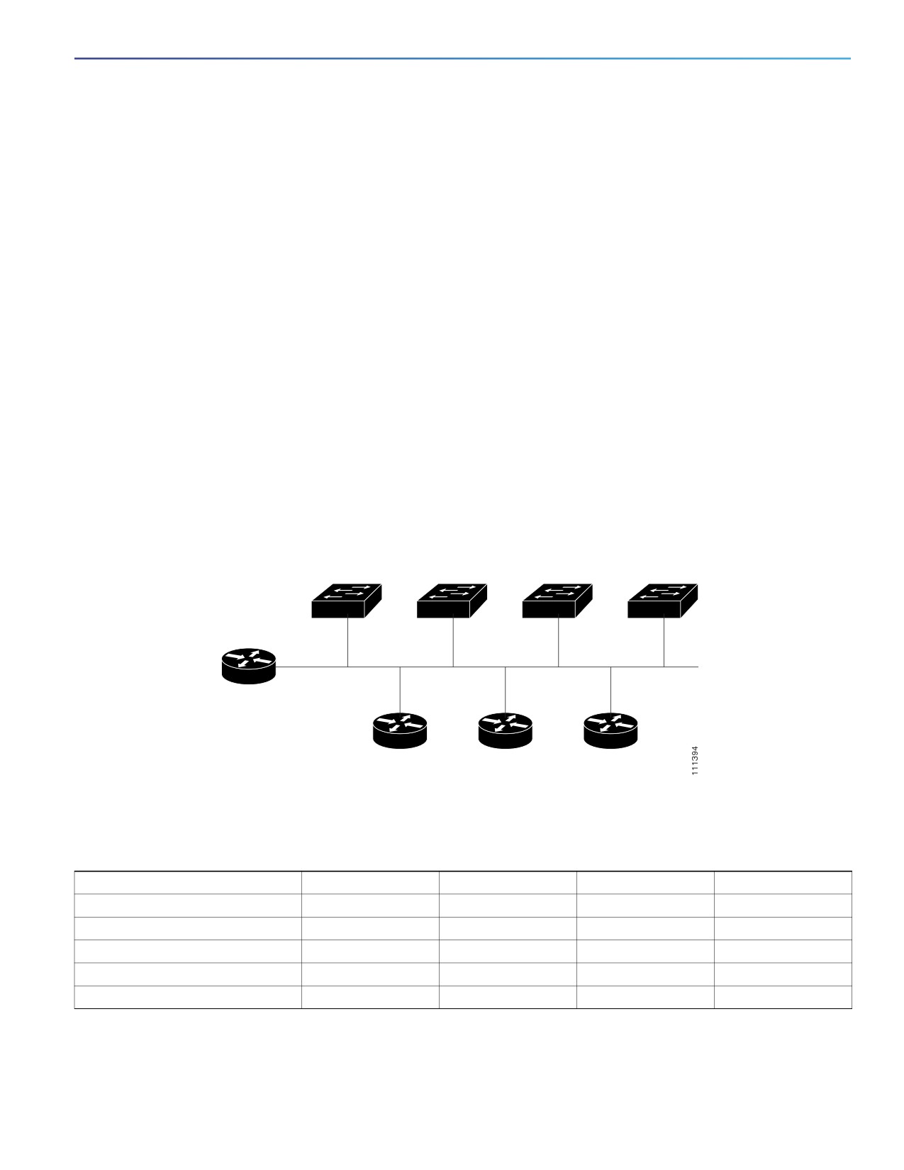
Retrieving IP Information Using DHCP-Based Autoconfiguration: Example
Switch A reads its configuration file as follows:
It obtains its IP address 10.0.0.21 from the DHCP server.
If no configuration filename is given in the DHCP server reply, Switch A reads the network-confg file from the base
directory of the TFTP server.
It adds the contents of the network-confg file to its host table.
It reads its host table by indexing its IP address 10.0.0.21 to its hostname (switcha).
It reads the configuration file that corresponds to its hostname; for example, it reads switch1-confg from the TFTP
server.
Switches B through D retrieve their configuration files and IP addresses in the same way.
Figure 4 on page 75 shows a sample network for retrieving IP information by using DHCP-based autoconfiguration.
Figure 4
DHCP-Based Autoconfiguration Network Example
Switch 1
Switch 2
Switch 3
Switch 4
00e0.9f1e.2001
00e0.9f1e.2002
00e0.9f1e.2003
00e0.9f1e.2004
Cisco router
10.0.0.10
10.0.0.1
10.0.0.2
10.0.0.3
DHCP server
DNS server
TFTP server
(tftpserver)
Table 15 on page 75 shows the configuration of the reserved leases on the DHCP server.
Table 15
DHCP Server Configuration
Switch A
Switch B
Switch C
Switch D
Binding key (hardware address)
00e0.9f1e.2001
00e0.9f1e.2002
00e0.9f1e.2003
00e0.9f1e.2004
IP address
10.0.0.21
10.0.0.22
10.0.0.23
10.0.0.24
Subnet mask
255.255.255.0
255.255.255.0
255.255.255.0
255.255.255.0
Router address
10.0.0.10
10.0.0.10
10.0.0.10
10.0.0.10
DNS server address
10.0.0.2
10.0.0.2
10.0.0.2
10.0.0.2
75

Performing Switch Setup Configuration
Configuration Examples for Performing Switch Setup Configuration
Table 15
DHCP Server Configuration (continued)
Switch A
Switch B
Switch C
Switch D
TFTP server name
tftpserver or
tftpserver or
tftpserver or
tftpserver or
10.0.0.3
10.0.0.3
10.0.0.3
10.0.0.3
Boot filename (configuration file)
switcha-confg
switchb-confg
switchc-confg
switchd-confg
(optional)
Hostname (optional)
switcha
switchb
switchc
switchd
DNS Server Configuration
The DNS server maps the TFTP server name tftpserver to IP address 10.0.0.3.
TFTP Server Configuration (on UNIX)
The TFTP server base directory is set to /tftpserver/work/. This directory contains the network-confg file used in the
two-file read method. This file contains the hostname to be assigned to the switch based on its IP address. The base
directory also contains a configuration file for each switch (switcha-confg, switchb-confg, and so forth) as shown in this
display:
prompt> cd /tftpserver/work/
prompt> ls
network-confg
switcha-confg
switchb-confg
switchc-confg
switchd-confg
prompt> cat network-confg
ip host switcha 10.0.0.21
ip host switchb 10.0.0.22
ip host switchc 10.0.0.23
ip host switchd 10.0.0.24
DHCP Client Configuration
No configuration file is present on Switch A through Switch D.
Scheduling Software Image Reload: Examples
This example shows how to reload the software on the switch on the current day at 7:30 p.m:
Switch# reload at 19:30
Reload scheduled for 19:30:00 UTC Wed Jun 5 1996 (in 2 hours and 25 minutes)
Proceed with reload? [confirm]
This example shows how to reload the software on the switch at a future time:
Switch# reload at 02:00 jun 20
Reload scheduled for 02:00:00 UTC Thu Jun 20 1996 (in 344 hours and 53 minutes)
Proceed with reload? [confirm]
To cancel a previously scheduled reload, use the reload cancel privileged EXEC command.
Configuring DHCP Auto-Image Update: Example
Switch# configure terminal
Switch(config)# ip dhcp pool pool1
Switch(dhcp-config)# network 10.10.10.0 255.255.255.0
Switch(dhcp-config)# bootfile config-boot.text
76
Performing Switch Setup Configuration
Configuration Examples for Performing Switch Setup Configuration
Switch(dhcp-config)# default-router 10.10.10.1
Switch(dhcp-config)# option 150 10.10.10.1
Switch(dhcp-config)# exit
Switch(config)# tftp-server flash:config-boot.text
Switch(config)# interface GigabitEthernet1/18
Switch(config-if)# no switchport
Switch(config-if)# ip address 10.10.10.1 255.255.255.0
Switch(config-if)# end
Configuring a Switch as a DHCP Server: Example
This example shows how to configure a switch as a DHCP server so it downloads a configuration file:
Switch# config terminal
Switch(config)# ip dhcp pool pool1
Switch(dhcp-config)# network 10.10.10.0 255.255.255.0
Switch(dhcp-config)# bootfile config-boot.text
Switch(dhcp-config)# default-router 10.10.10.1
Switch(dhcp-config)# option 150 10.10.10.1
Switch(dhcp-config)# option 125 hex 0000.0009.0a05.08661.7574.6f69.6e73.7461.6c6c.5f64.686370
Switch(dhcp-config)# exit
Switch(config)# tftp-server flash:config-boot.text
Switch(config)# tftp-server flash:c-ipservices-mz.122-44.3.SE.tar
Switch(config)# tftp-server flash:ies-lanbase-tar.122-44.EX.tar
Switch(config)# tftp-server flash:boot-config.text
Switch(config)# tftp-server flash: autoinstall_dhcp
Switch(config)# interface GigabitEthernet1/18
Switch(config-if)# no switchport
Switch(config-if)# ip address 10.10.10.1 255.255.255.0
Switch(config-if)# end
Configuring Client to Download Files from DHCP Server
This example uses a Layer 3 SVI interface on VLAN 99 to enable DHCP-based autoconfiguration with a saved
configuration:
Switch# configure terminal
Switch(conf)# boot host dhcp
Switch(conf)# boot host retry timeout 300
Switch(conf)# banner config-save ^C Caution - Saving Configuration File to NVRAM May Cause You to
Nolonger Automatically Download Configuration Files at Reboot^C
Switch(config)# vlan 99
Switch(config-vlan)# interface vlan 99
Switch(config-if)# no shutdown
Switch(config-if)# end
Switch# show boot
BOOT path-list:
Config file:
flash:/config.text
Private Config file:
flash:/private-config.text
Enable Break:
no
Manual Boot:
no
HELPER path-list:
NVRAM/Config file
buffer size:
32768
Timeout for Config
Download:
300 seconds
Config Download
via DHCP:
enabled (next boot: enabled)
Switch#
77

Performing Switch Setup Configuration
Additional References
Additional References
The following sections provide references related to switch administration:
Standards
Standards
Title
No new or modified standards are supported by this
—
feature, and support for existing standards has not
been modified by this feature.
MIBs
MIBs
MIBs Link
—
To locate and download MIBs using Cisco IOS XR software, use the
Cisco MIB Locator found at the following URL and choose a platform
under the Cisco Access Products menu:
RFCs
RFCs
Title
No new or modified RFCs are supported by this
—
feature, and support for existing RFCs has not been
modified by this feature.
Technical Assistance
Description
Link
The Cisco Technical Support website contains
thousands of pages of searchable technical content,
including links to products, technologies, solutions,
technical tips, and tools. Registered Cisco.com users
can log in from this page to access even more content.
78
Configuring Cisco IOS Configuration
Engine
Prerequisites for Configuring Cisco IOS Configuration
Engine
Set the CNS DeviceID
When using the Cisco Configuration Engine user interface, you must first set the DeviceID field to the hostname value
that the switch acquires after, not before, you use the cns config initial global configuration command at the switch.
Otherwise, subsequent cns config partial global configuration command operations malfunction.
Enable Automated CNS Configuration
To enable automated CNS configuration of the switch, you must first complete the prerequisites in Table 1. When
you complete them, power on the switch. At the setup prompt, you do not need to enter a command. The switch
begins the initial configuration as described in the Initial Configuration, page 83. When the full configuration file is
loaded on your switch, you do not need to do anything else.
79

Configuring Cisco IOS Configuration Engine
Information About Configuring Cisco IOS Configuration Engine
Device
Required Configuration
Access switch
Factory default (no configuration file)
Distribution switch
IP helper address
Enable DHCP relay agent
IP routing (if used as default gateway)
DHCP server
IP address assignment
TFTP server IP address
Path to bootstrap configuration file on the TFTP server
Default gateway IP address
TFTP server
A bootstrap configuration file that includes the CNS configuration
commands that enable the switch to communicate with the
Configuration Engine
The switch configured to use either the switch MAC address or the serial
number (instead of the default hostname) to generate the ConfigID and
EventID
The CNS event agent configured to push the configuration file to the
switch
CNS Configuration Engine
One or more templates for each type of device, with the ConfigID of the
device mapped to the template
Information About Configuring Cisco IOS Configuration Engine
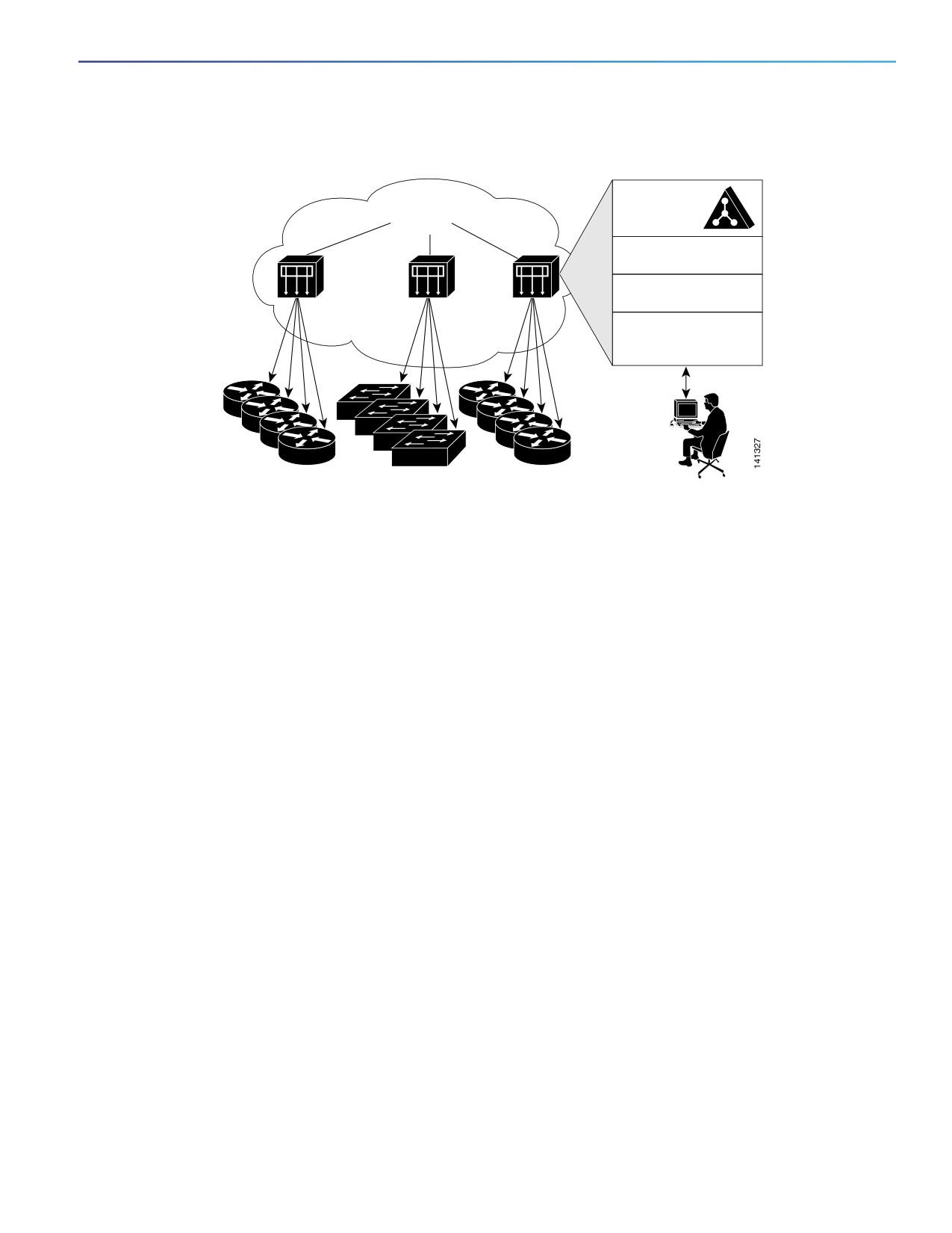
Cisco Configuration Engine is network management software that acts as a configuration service for automating the
deployment and management of network devices and services (see Figure 5 on page 81). Each Cisco Configuration
Engine service manages a group of Cisco devices (switches and routers) and the services that they deliver, storing their
configurations and delivering them as needed. Cisco Configuration Engine automates initial configurations and
configuration updates by generating device-specific configuration changes, sending them to the device, executing the
configuration change, and logging the results.
Cisco Configuration Engine supports standalone and server modes and has these CNS components:
Configuration service (web server, file manager, and namespace mapping server)
Event service (event gateway)
Data service directory (data models and schema)
In standalone mode, Cisco Configuration Engine supports an embedded directory service. In this mode, no external
directory or other data store is required. In server mode, Cisco Configuration Engine supports a user-defined external
directory.
80
Configuring Cisco IOS Configuration Engine
Information About Configuring Cisco IOS Configuration Engine
Figure 5
Configuration Engine Architectural Overview
Service provider network
Data service
Configuration
directory
engine
Configuration server
Event service
Web-based
user interface
Order entry
configuration management
Configuration Service
Configuration Service is the core component of Cisco Configuration Engine. It consists of a configuration server that
works with Cisco IOS CNS agents on the switch. Configuration Service delivers device and service configurations to the
switch for initial configuration and mass reconfiguration by logical groups. Switches receive their initial configuration from
the Configuration Service when they start up on the network for the first time.
Configuration Service uses CNS Event Service to send and receive configuration change events and to send success and
failure notifications.
The configuration server is a web server that uses configuration templates and the device-specific configuration
information stored in the embedded (standalone mode) or remote (server mode) directory.
Configuration templates are text files containing static configuration information in the form of CLI commands. In the
templates, variables are specified using Lightweight Directory Access Protocol (LDAP) URLs that reference the
device-specific configuration information stored in a directory.
The Cisco IOS agent can perform a syntax check on received configuration files and publish events to show the success
or failure of the syntax check. The configuration agent can either apply configurations immediately or delay the
application until receipt of a synchronization event from the configuration server.
Event Service
Cisco Configuration Engine uses Event Service for receipt and generation of configuration events. The event agent is on
the switch and facilitates the communication between the switch and the event gateway on Configuration Engine.
Event Service is a highly capable publish-and-subscribe communication method. Event Service uses subject-based
addressing to send messages to their destinations. Subject-based addressing conventions define a simple, uniform
namespace for messages and their destinations.
81
Configuring Cisco IOS Configuration Engine
Information About Configuring Cisco IOS Configuration Engine
NameSpace Mapper
Configuration Engine includes NameSpace Mapper (NSM), which provides a lookup service for managing logical groups
of devices based on application, device or group ID, and event.
Cisco IOS devices recognize only event subject names that match those configured in Cisco IOS software; for example,
cisco.cns.config.load. You can use the namespace mapping service to designate events by using any desired naming
convention. When you have populated your data store with your subject names, NSM changes your event subject-name
strings to those known by Cisco IOS.
For a subscriber, when given a unique device ID and event, the namespace mapping service returns a set of events to
which to subscribe. Similarly, for a publisher, when given a unique group ID, device ID, and event, the mapping service
returns a set of events on which to publish.
CNS IDs and Device Hostnames
Configuration Engine assumes that a unique identifier is associated with each configured switch. This unique identifier
can take on multiple synonyms, where each synonym is unique within a particular namespace. The event service uses
namespace content for subject-based addressing of messages.
Configuration Engine intersects two namespaces, one for the event bus and the other for the configuration server. Within
the scope of the configuration server namespace, the term ConfigID is the unique identifier for a device. Within the scope
of the event bus namespace, the term DeviceID is the CNS unique identifier for a device.
Because Configuration Engine uses both the event bus and the configuration server to provide configurations to devices,
you must define both ConfigID and Device ID for each configured switch.
Within the scope of a single instance of the configuration server, no two configured switches can share the same value
for ConfigID. Within the scope of a single instance of the event bus, no two configured switches can share the same value
for DeviceID.
ConfigID
Each configured switch has a unique ConfigID, which serves as the key into the Configuration Engine directory for the
corresponding set of switch CLI attributes. The ConfigID defined on the switch must match the ConfigID for the
corresponding switch definition on Configuration Engine.
The ConfigID is fixed at startup time and cannot be changed until the device restarts, even if the switch hostname is
reconfigured.
DeviceID
Each configured switch participating on the event bus has a unique DeviceID, which is analogous to the switch source
address so that the switch can be targeted as a specific destination on the bus. All switches configured with the cns
config partial global configuration command must access the event bus. Therefore, the DeviceID, as originated on the
switch, must match the DeviceID of the corresponding switch definition in Configuration Engine.
The origin of the DeviceID is defined by the Cisco IOS hostname of the switch. However, the DeviceID variable and its
usage reside within the event gateway adjacent to the switch.
The logical Cisco IOS termination point on the event bus is embedded in the event gateway, which in turn functions as a
proxy on behalf of the switch. The event gateway represents the switch and its corresponding DeviceID to the event bus.
The switch declares its hostname to the event gateway immediately after the successful connection to the event gateway.
The event gateway couples the DeviceID value to the Cisco IOS hostname each time this connection is established. The
event gateway caches this DeviceID value for the duration of its connection to the switch.
82
Configuring Cisco IOS Configuration Engine
Information About Configuring Cisco IOS Configuration Engine
Hostname and DeviceID Interaction
The DeviceID is fixed at the time of the connection to the event gateway and does not change even when the switch
hostname is reconfigured.
When changing the switch hostname on the switch, the only way to refresh the DeviceID is to break the connection
between the switch and the event gateway. Enter the no cns event global configuration command followed by the cns
event global configuration command.
When the connection is reestablished, the switch sends its modified hostname to the event gateway. The event gateway
redefines the DeviceID to the new value.
Using Hostname, DeviceID, and ConfigID
In standalone mode, when a hostname value is set for a switch, the configuration server uses the hostname as the
DeviceID when an event is sent on hostname. If the hostname has not been set, the event is sent on the cn=<value> of
the device.
In server mode, the hostname is not used. In this mode, the unique DeviceID attribute is always used for sending an event
on the bus. If this attribute is not set, you cannot update the switch.
These and other associated attributes (tag value pairs) are set when you run Setup on Configuration Engine.
Cisco IOS Agents
The CNS event agent feature allows the switch to publish and subscribe to events on the event bus and works with the
Cisco IOS agent.
Initial Configuration
When the switch first comes up, it attempts to get an IP address by broadcasting a DHCP request on the network.
Assuming there is no DHCP server on the subnet, the distribution switch acts as a DHCP relay agent and forwards the
request to the DHCP server. Upon receiving the request, the DHCP server assigns an IP address to the new switch and
includes the TFTP server IP address, the path to the bootstrap configuration file, and the default gateway IP address in
a unicast reply to the DHCP relay agent. The DHCP relay agent forwards the reply to the switch.
The switch automatically configures the assigned IP address on interface VLAN 1 (the default) and downloads the
bootstrap configuration file from the TFTP server. Upon successful download of the bootstrap configuration file, the
switch loads the file in its running configuration.
The Cisco IOS agents initiate communication with Configuration Engine by using the appropriate ConfigID and EventID.
Configuration Engine maps the ConfigID to a template and downloads the full configuration file to the switch.
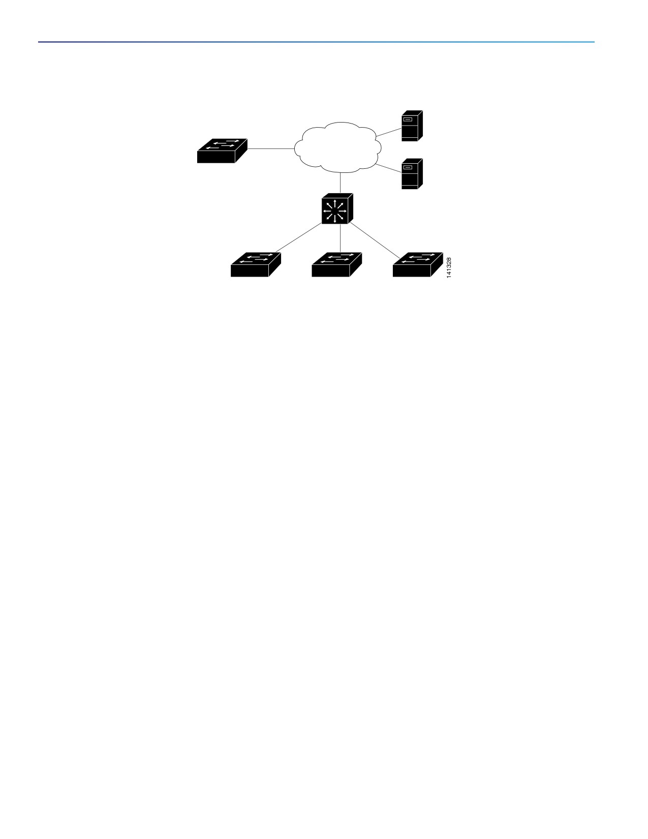
Figure 6 on page 84 shows a sample network configuration for retrieving the initial bootstrap configuration file by using
DHCP-based autoconfiguration.
83
Configuring Cisco IOS Configuration Engine
How to Configure Cisco IOS Configuration Engine
Figure 6
Initial Configuration Overview
TFTP
server
Configuration
WAN
Engine
V
DHCP
server
DHCP relay agent
Distribution layer
default gateway
Access layer
switches
Incremental (Partial) Configuration
After the network is running, new services can be added by using the Cisco IOS agent. Incremental (partial)
configurations can be sent to the switch. The actual configuration can be sent as an event payload by way of the event
gateway (push operation) or as a signal event that triggers the switch to initiate a pull operation.
The switch can check the syntax of the configuration before applying it. If the syntax is correct, the switch applies the
incremental configuration and publishes an event that signals success to the configuration server. If the switch does not
apply the incremental configuration, it publishes an event showing an error status. When the switch has applied the
incremental configuration, it can write it to NVRAM or wait until signaled to do so.
Synchronized Configuration
When the switch receives a configuration, it can defer application of the configuration upon receipt of a write-signal
event. The write-signal event tells the switch not to save the updated configuration into its NVRAM. The switch uses the
updated configuration as its running configuration. This ensures that the switch configuration is synchronized with other
network activities before saving the configuration in NVRAM for use at the next reboot.
How to Configure Cisco IOS Configuration Engine
Configuring Cisco IOS Agents
CNS Event Agent and Cisco IOS CNS Agent embedded in the Cisco IOS software on the switch allows the switch to be
connected and automatically configured. Both agents must be enabled and the CNS configuration can be initial or
partial. The partial configuration allows you to use Configuration Engine to remotely send incremental configuration to
the switch.
Enabling CNS Event Agent
Before You Begin
You must enable CNS Event Agent on the switch before you enable Cisco IOS CNS Agent.
84

Configuring Cisco IOS Configuration Engine
Configuring Cisco IOS Agents
Command
Purpose
1.
configure terminal
Enters global configuration mode.
2.
cns event {hostname | ip-address} [port-number]
Enables the event agent, and enters the gateway
[backup] [failover-time seconds] [keepalive seconds
parameters.
retry-count] [reconnect time] [source ip-address]
{hostname | ip-address}—Enters either the hostname
or the IP address of the event gateway.
(Optional) port number—Enters the port number for
the event gateway. The default port number is 11011.
(Optional) backup—Shows that this is the backup
gateway. (If omitted, this is the primary gateway.)
(Optional) failover-time seconds—Enters how long
the switch waits for the primary gateway route after
the route to the backup gateway is established.
(Optional) keepalive seconds—Enters how often the
switch sends keepalive messages. For retry-count,
enters the number of unanswered keepalive
messages that the switch sends before the
connection is terminated. The default for each is 0.
(Optional) reconnect time—Enters the maximum time
interval that the switch waits before trying to
reconnect to the event gateway.
(Optional) source ip-address—Enters the source IP
address of this device.
Note: Though visible in the command-line help string, the
encrypt and the clock-timeout time keywords are not
supported.
3.
end
Returns to privileged EXEC mode.
4.
show cns event connections
Verifies information about the event agent.
Enabling Cisco IOS CNS Agent and an Initial Configuration
Command
Purpose
1.
configure terminal
Enters global configuration mode.
2.
cns template connect name
Enters CNS template connect configuration mode, and specifies
the name of the CNS connect template.
3.
cli config-text
Enters a command line for the CNS connect template. Repeat
this step for each command line in the template.
4.
Repeat Steps 2 to 3 to configure another CNS connect template.
5.
exit
Returns to global configuration mode.
85

Configuring Cisco IOS Configuration Engine
Configuring Cisco IOS Agents
Command
Purpose
6.
cns connect name [retries number]
Enters CNS connect configuration mode, specifies the name of
[retry-interval seconds] [sleep seconds]
the CNS connect profile, and defines the profile parameters. The
[timeout seconds]
switch uses the CNS connect profile to connect to
Configuration Engine.
(Optional) retries number—Enters the number of connection
retries. The range is 1 to 30. The default is 3.
(Optional) retry-interval seconds—Enters the interval
between successive connection attempts to the
Configuration Engine. The range is 1 to 40 seconds. The
default is 10 seconds.
(Optional) sleep seconds—Enters the amount of time before
which the first connection attempt occurs. The range is 0 to
250 seconds. The default is 0.
(Optional) timeout seconds—Enters the amount of time after
which the connection attempts end. The range is 10 to 2000
seconds. The default is 120.
7.
discover {controller controller-type | dlci
Specifies the interface parameters in the CNS connect profile.
[subinterface subinterface-number] |
interface [interface-type] | line line-type}
controller controller-type—Enters the controller type.
dlci—Enters the active data-link connection identifiers
(DLCIs).
(Optional) subinterface subinterface-number—Specifies the
point-to-point subinterface number that is used to search
for active DLCIs.
interface [interface-type]—Enters the type of interface.
line line-type—Enters the line type.
8.
template name [ ... name]
Specifies the list of CNS connect templates in the CNS connect
profile to be applied to the switch configuration. You can specify
more than one template.
9.
Repeat Steps 7 to 8 to specify more interface parameters and
CNS connect templates in the CNS connect profile.
10.
exit
Returns to global configuration mode.
11.
hostname name
Enters the hostname for the switch.
12.
ip route network-number
(Optional) Establishes a static route to Configuration Engine
whose IP address is network-number.
86
Configuring Cisco IOS Configuration Engine
Configuring Cisco IOS Agents
Command
Purpose
13.
cns id interface num {dns-reverse | ipaddress
(Optional) Sets the unique EventID or ConfigID used by the
| mac-address} [event] [image]
Configuration Engine.
or
interface num—Enters the type of interface for example,
ethernet, group-async, loopback, or virtual-template. This
cns id {hardware-serial | hostname | string
setting specifies from which interface the IP or MAC address
string | udi} [event] [image]
should be retrieved to define the unique ID.
dns-reverse—Retrieves the hostname and assigns it as the
unique ID.
ipaddress—Uses the IP address.
mac-address—Uses the MAC address as the unique ID.
(Optional) event—Sets the ID to be the eventID value used to
identify the switch.
(Optional) image—Sets the ID to be the imageID value used
to identify the switch.
Note: If the event and image keywords are omitted, the imageID
value is used to identify the switch.
hardware-serial—Sets the switch serial number as the
unique ID.
hostname (the default)—Selects the switch hostname as the
unique ID, uses an arbitrary text string string string as the
unique ID and udi sets the unique device identifier (UDI) as
the unique ID.
87

Configuring Cisco IOS Configuration Engine
Configuring Cisco IOS Agents
Command
Purpose
14.
cns config initial {hostname | ip-address}
Enables the Cisco IOS agent and initiates an initial configuration.
[port-number] [event] [no-persist] [page
page] [source ip-address] [syntax-check]
{hostname | ip-address}—Enters the hostname or the
IP address of the configuration server.
(Optional) port-number—Enters the port number of the
configuration server. The default port number is 80.
(Optional) event—Enables configuration success, failure, or
warning messages when the configuration is finished.
(Optional) no-persist—Suppresses the automatic writing to
NVRAM of the configuration pulled as a result of entering the
cns config initial global configuration command. If the
no-persist keyword is not entered, using the cns config
initial command causes the resultant configuration to be
automatically written to NVRAM.
(Optional) page page—Enters the web page of the initial
configuration. The default is /Config/config/asp.
(Optional) source ip-address—Enters the source IP address.
(Optional) syntax-check—Checks the syntax when this
parameter is entered.
Note: Though visible in the command-line help string, the
encrypt, status url, and inventory keywords are not
supported.
15.
end
Returns to privileged EXEC mode.
Enabling a Partial Configuration
Command
Purpose
1.
configure terminal
Enters global configuration mode.
2.
cns config partial {ip-address | hostname}
Enables the configuration agent, and initiates a partial
[port-number] [source ip-address]
configuration.
{ip-address | hostname}—Enters the IP address or the
hostname of the configuration server.
(Optional) port-number—Enters the port number of the
configuration server. The default port number is 80.
(Optional) source ip-address—Enters the source IP
address.
Note: Though visible in the command-line help string, the
encrypt keyword is not supported.
3.
end
Returns to privileged EXEC mode.
88

Configuring Cisco IOS Configuration Engine
Monitoring and Maintaining Cisco IOS Configuration Engine
Monitoring and Maintaining Cisco IOS Configuration Engine
Command
Purpose
show cns config connections
Displays the status of the CNS Cisco IOS agent connections.
show cns config outstanding
Displays information about incremental (partial) CNS configurations that
have started but are not yet completed.
show cns config stats
Displays statistics about the Cisco IOS agent.
show cns event connections
Displays the status of the CNS event agent connections.
show cns event stats
Displays statistics about the CNS event agent.
show cns event subject
Displays a list of event agent subjects that are subscribed to by
applications.
Configuration Examples for Cisco IOS Configuration Engine
Enabling the CNS Event Agent: Example
This example shows how to enable the CNS event agent, set the IP address gateway to 10.180.1.27, set 120 seconds
as the keepalive interval, and set 10 as the retry count.
Switch(config)# cns event 10.180.1.27 keepalive 120 10
Configuring an Initial CNS Configuration: Examples
This example shows how to configure an initial configuration on a remote switch when the switch configuration is
unknown (the CNS Zero Touch feature).
Switch(config)# cns template connect template-dhcp
Switch(config-tmpl-conn)# cli ip address dhcp
Switch(config-tmpl-conn)# exit
Switch(config)# cns template connect ip-route
Switch(config-tmpl-conn)# cli ip route 0.0.0.0 0.0.0.0
${next-hop}
Switch(config-tmpl-conn)# exit
Switch(config)# cns connect dhcp
Switch(config-cns-conn)# discover interface gigabitethernet
Switch(config-cns-conn)# template template-dhcp
Switch(config-cns-conn)# template ip-route
Switch(config-cns-conn)# exit
Switch(config)# hostname RemoteSwitch
RemoteSwitch(config)# cns config initial 10.1.1.1 no-persist
This example shows how to configure an initial configuration on a remote switch when the switch IP address is known.
The Configuration Engine IP address is 172.28.129.22.
Switch(config)# cns template connect template-dhcp
Switch(config-tmpl-conn)# cli ip address dhcp
Switch(config-tmpl-conn)# exit
Switch(config)# cns template connect ip-route
Switch(config-tmpl-conn)# cli ip route 0.0.0.0 0.0.0.0
${next-hop}
Switch(config-tmpl-conn)# exit
Switch(config)# cns connect dhcp
Switch(config-cns-conn)# discover interface gigabitethernet
Switch(config-cns-conn)# template template-dhcp
Switch(config-cns-conn)# template ip-route
89

Configuring Cisco IOS Configuration Engine
Additional References
Switch(config-cns-conn)# exit
Switch(config)# hostname RemoteSwitch
RemoteSwitch(config)# ip route 172.28.129.22 255.255.255.255 11.11.11.1
RemoteSwitch(config)# cns id ethernet 0 ipaddress
RemoteSwitch(config)# cns config initial 172.28.129.22 no-persist
Additional References
The following sections provide references related to switch administration:
Related Documents
Related Topic
Document Title
Network management commands
Cisco IOS Network Management Command Reference
Standards
Standards
Title
No new or modified standards are supported by this
—
feature, and support for existing standards has not
been modified by this feature.
MIBs
MIBs
MIBs Link
—
To locate and download MIBs using Cisco IOS XR software, use the
Cisco MIB Locator found at the following URL and choose a platform
under the Cisco Access Products menu:
RFCs
RFCs
Title
No new or modified RFCs are supported by this
—
feature, and support for existing RFCs has not been
modified by this feature.
Technical Assistance
Description
Link
The Cisco Technical Support website contains
thousands of pages of searchable technical content,
including links to products, technologies, solutions,
technical tips, and tools. Registered Cisco.com users
can log in from this page to access even more content.
90
Configuring Switch Clusters
This chapter provides the concepts and procedures to create and manage switch clusters on your switch. You can create
and manage switch clusters by using the command-line interface (CLI), Cisco Network Assistant (CNA) or SNMP. For
information about CNA, see the online help for CNA.
This chapter provides information about switch clusters. It also includes guidelines and limitations for clusters mixed with
other cluster-capable Catalyst switches, but it does not provide complete descriptions of the cluster features for
switches in the cluster. For complete cluster information for a specific Catalyst platform, refer to the software
configuration guide for that switch.
Cluster Command Switch Characteristics
A cluster command switch must meet these requirements:
Has an IP address.
Has Cisco Discovery Protocol (CDP) version 2 enabled (the default).
Is not a command or cluster member switch of another cluster.
Is connected to the standby cluster command switches through the management VLAN and to the cluster member
switches through a common VLAN.
Standby Cluster Command Switch Characteristics
A standby cluster command switch must meet these requirements:
Has an IP address.
Has CDP version 2 enabled.
Is connected to the command switch and to other standby command switches through its management VLAN.
Is connected to all other cluster member switches (except the cluster command and standby command switches)
through a common VLAN.
Is redundantly connected to the cluster so that connectivity to cluster member switches is maintained.
Is not a command or member switch of another cluster.
Candidate Switch and Cluster Member Switch Characteristics
Candidate switches are cluster-capable switches that have not yet been added to a cluster. Cluster member switches
are switches that have actually been added to a switch cluster. Although not required, a candidate or cluster member
switch can have its own IP address and password (for related considerations, see IP Addresses, page 99 and Passwords,
page 100).
To join a cluster, a candidate switch must meet these requirements:
Is running cluster-capable software.
91
Configuring Switch Clusters
Restrictions for Configuring Switch Clusters
Has CDP version 2 enabled.
Is not a command or cluster member switch of another cluster.
If a cluster standby group exists, the switch is connected to every standby cluster command switch through at least
one common VLAN. The VLAN to each standby cluster command switch can be different.
Is connected to the cluster command switch through at least one common VLAN.
Catalyst 1900, Catalyst 2820, Catalyst 2900 XL, Catalyst 2950, and Catalyst 3500 XL candidate and cluster
member switches must be connected through their management VLAN to the cluster command switch and
standby cluster command switches. For complete information about these switches in a switch-cluster
environment, refer to the software configuration guide for that specific switch.
This requirement does not apply if you have a Catalyst 2970, Catalyst 3550, Catalyst 3560, or Catalyst 3750
cluster command switch. Candidate and cluster member switches can connect through any VLAN in common
with the cluster command switch.
Restrictions for Configuring Switch Clusters
We do not recommend using the ip http access-class global configuration command to limit access to specific hosts
or networks. Access should be controlled through the cluster command switch or by applying access control lists (ACLs)
on interfaces that are configured with IP address. For more information on ACLs, see Configuring Network Security with
ACLs, page 575
Information About Configuring Switch Clusters
A switch cluster is a set of up to 16 connected, cluster-capable Catalyst switches that are managed as a single entity.
The switches in the cluster use the switch clustering technology so that you can configure and troubleshoot a group of
different Catalyst desktop switch platforms through a single IP address.
In a switch cluster, one switch must be the cluster command switch and up to 15 other switches can be cluster member
switches. The total number of switches in a cluster cannot exceed 16 switches. The cluster command switch is the single
point of access used to configure, manage, and monitor the cluster member switches. Cluster members can belong to
only one cluster at a time.
Benefits of Clustering Switches
Management of switches regardless of their interconnection media and their physical locations. The switches can
be in the same location, or they can be distributed across a Layer 2 or Layer 3 (if your cluster is using a
Catalyst 3550, Catalyst 3560, or Catalyst 3750 switch as a Layer 3 router between the Layer 2 switches in the
cluster) network.
Cluster members are connected to the cluster command switch according to the connectivity guidelines described
in the Automatic Discovery of Cluster Candidates and Members, page 94. This section includes management VLAN
considerations for the Catalyst 1900, Catalyst 2820, Catalyst 2900 XL, Catalyst 2950, and Catalyst 3500 XL
switches. For complete information about these switches in a switch-cluster environment, refer to the software
configuration guide for that specific switch.
Command-switch redundancy if a cluster command switch fails. One or more switches can be designated as
standby cluster command switches to avoid loss of contact with cluster members. A cluster standby group is a group
of standby cluster command switches.
Management of a variety of switches through a single IP address. This preserves IP addresses, especially if you have
a limited number of them. All communication with the switch cluster is through the cluster command switch IP
address.
92

Configuring Switch Clusters
How to Plan for Switch Clustering
Eligible Cluster Switches
Table 1 lists the switches eligible for switch clustering, including which ones can be cluster command switches and
which ones can only be cluster member switches, and the required software versions.
Table 16
Eligible Switch Clusters
Switch
Cisco IOS Release
Cluster Capability
IE 2000
15.0(2)EA1 or later
Member or command switch
IE 3010
12.2(53)EZ or later
Member or command switch
IE 3000
12.2(40)EX or later
Member or command switch
IE 4000
15.2(2)EA or later
Member or command switch
IE 4010
15.2(4)EC or later
Member or command switch
IE 5000
15.2(2)EB or later
Member or command switch
Catalyst 3750-E or Catalyst 3560-E
12.2(35)SE2 or later
Member or command switch
Catalyst 3750
12.1(11)AX or later
Member or command switch
Catalyst 3560
12.1(19)EA1b or later
Member or command switch
Catalyst 3550
12.1(4)EA1 or later
Member or command switch
Catalyst 2975
12.2(46)EX or later
Member or command switch
Catalyst 2970
12.1(11)AX or later
Member or command switch
Catalyst 2960-S
12.2(53)SE or later
Member or command switch
Catalyst 2960
12.2(25)FX or later
Member or command switch
Catalyst 2955
12.1(12c)EA1 or later
Member or command switch
Catalyst 2950
12.0(5.2)WC(1) or later
Member or command switch
Catalyst 2950 LRE
12.1(11)JY or later
Member or command switch
Catalyst 2940
12.1(13)AY or later
Member or command switch
Catalyst 3500 XL
12.0(5.1)XU or later
Member or command switch
Catalyst 2900 XL (8-MB switches)
12.0(5.1)XU or later
Member or command switch
Catalyst 2900 XL (4-MB switches)
11.2(8.5)SA6 (recommended)
Member switch only
Catalyst 1900 and 2820
9.00(-A or -EN) or later
Member switch only
How to Plan for Switch Clustering
Anticipating conflicts and compatibility issues is a high priority when you manage several switches through a cluster. This
section describes the guidelines, requirements, and caveats that you should understand before you create the cluster:
Automatic Discovery of Cluster Candidates and Members, page 94
IP Addresses, page 99
Hostnames, page 99
Passwords, page 100
SNMP Community Strings, page 100
TACACS+ and RADIUS, page 100
93
Configuring Switch Clusters
How to Plan for Switch Clustering
LRE Profiles, page 100
Refer to the release notes for the list of Catalyst switches eligible for switch clustering, including which ones can be
cluster command switches and which ones can only be cluster member switches, and for the required software versions
and browser and Java plug-in configurations.
Automatic Discovery of Cluster Candidates and Members
The cluster command switch uses Cisco Discovery Protocol (CDP) to discover cluster member switches, candidate
switches, neighboring switch clusters, and edge devices across multiple VLANs and in star or cascaded topologies.
Note: Do not disable CDP on the cluster command switch, on cluster members, or on any cluster-capable switches that
you might want a cluster command switch to discover. For more information about CDP, see Configuring CDP, page 529
Following these connectivity guidelines ensures automatic discovery of the switch cluster, cluster candidates, connected
switch clusters, and neighboring edge devices:
Discovery Through CDP Hops, page 94
Discovery Through Non-CDP-Capable and Noncluster-Capable Devices, page 95
Discovery Through Different VLANs, page 96
Discovery Through Different Management VLANs, page 97
Discovery Through Routed Ports, page 97
Discovery of Newly Installed Switches, page 98
Discovery Through CDP Hops
By using CDP, a cluster command switch can discover switches up to seven CDP hops away (the default is three hops)
from the edge of the cluster. The edge of the cluster is where the last cluster member switches are connected to the
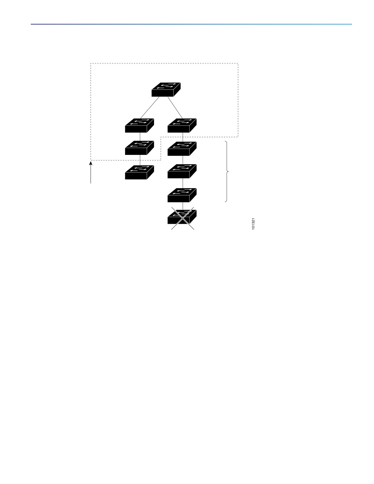
cluster and to candidate switches. For example, cluster member switches 9 and 10 in Figure 7 on page 95 are at the
edge of the cluster.
In Figure 7 on page 95, the cluster command switch has ports assigned to VLANs 16 and 62. The CDP hop count is three.
The cluster command switch discovers switches 11, 12, 13, and 14 because they are within three hops from the edge
of the cluster. It does not discover switch 15 because it is four hops from the edge of the cluster.
94
Configuring Switch Clusters
How to Plan for Switch Clustering
Figure 7
Discovery Through CDP Hops
Command device
VLAN 16
VLAN 62
Member
Member
device 8
device 10
Member
Device 12
device 9
Device 11
candidate
Device 13
Candidate
device
devices
Edge of
cluster
Device 14
Device 15
Discovery Through Non-CDP-Capable and Noncluster-Capable Devices
If a cluster command switch is connected to a non-CDP-capable third-party hub (such as a non-Cisco hub), it can
discover cluster-enabled devices connected to that third-party hub. However, if the cluster command switch is
connected to a noncluster-capable Cisco device, it cannot discover a cluster-enabled device connected beyond the
noncluster-capable Cisco device.
Figure 8 on page 96 shows that the cluster command switch discovers the switch that is connected to a third-party hub.
However, the cluster command switch does not discover the switch that is connected to a Catalyst 5000 switch.
95