Cisco Industrial Ethernet 4000, 4010 and 5000 Switch Software. Configuration Guide (2022) - page 6

Configuring Switch Clusters
How to Plan for Switch Clustering
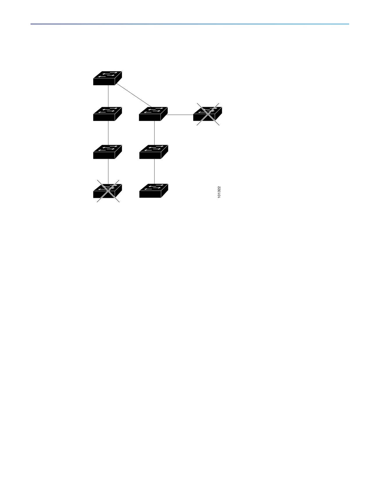
Figure 8
Discovery Through Non-CDP-Capable and Noncluster-Capable Devices
Command device
Third-party hub
Catalyst 6500 switch
(non-CDP-capable)
(noncluster-capable)
Candidate device
Candidate device
Discovery Through Different VLANs
If the cluster command switch is a Catalyst 2970, Catalyst 3550, Catalyst 3560, or Catalyst 3750 switch, the cluster can
have cluster member switches in different VLANs. As cluster member switches, they must be connected through at least
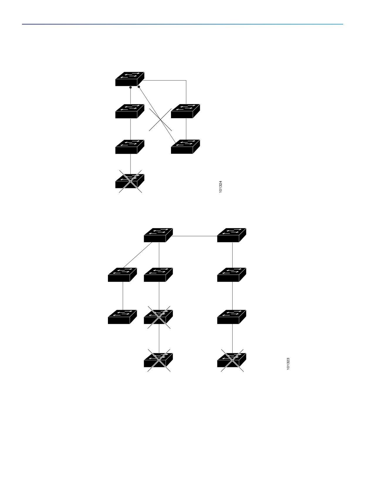
one VLAN in common with the cluster command switch. The cluster command switch in Figure 9 on page 97 has ports
assigned to VLANs 9, 16, and 62 and therefore discovers the switches in those VLANs. It does not discover the switch
in VLAN 50. It also does not discover the switch in VLAN 16 in the first column because the cluster command switch has
no VLAN connectivity to it.
Catalyst 2900 XL, Catalyst 2950, and Catalyst 3500 XL cluster member switches must be connected to the cluster
command switch through their management VLAN. For information about discovery through management VLANs, see
Discovery Through Different Management VLANs, page 97.
96
Configuring Switch Clusters
How to Plan for Switch Clustering
Figure 9
Discovery Through Different VLANs
Command device
VLAN 62
VLAN trunk 9,16
VLAN 50
VLAN 62
VLAN trunk 9,16
VLAN 16
VLAN trunk 4,16
Discovery Through Different Management VLANs
Catalyst 2970, Catalyst 3550, Catalyst 3560, or Catalyst 3750 cluster command switches can discover and manage
cluster member switches in different VLANs and different management VLANs. As cluster member switches, they must
be connected through at least one VLAN in common with the cluster command switch. They do not need to be connected
to the cluster command switch through their management VLAN. The default management VLAN is VLAN 1.
Note: If the switch cluster has a Catalyst 3750 or 2975 switch or has a switch stack, that switch or switch stack must be
the cluster command switch.
The cluster command switch and standby command switch in Figure 11 on page 98 (assuming they are Catalyst 2960,
Catalyst 2970, Catalyst 2975, Catalyst 3550, Catalyst 3560, or Catalyst 3750 cluster command switches) have ports
assigned to VLANs 9, 16, and 62. The management VLAN on the cluster command switch is VLAN 9. Each cluster
command switch discovers the switches in the different management VLANs except these:
Switches 7 and 10 (switches in management VLAN 4) because they are not connected through a common VLAN
(meaning VLANs 62 and 9) with the cluster command switch
Switch 9 because automatic discovery does not extend beyond a noncandidate device, which is switch 7
Discovery Through Routed Ports
Note: The LAN Base image supports static routing.
If the cluster command switch has a routed port (RP) configured, it discovers only candidate and cluster member
switches in the same VLAN as the routed port.
The Layer 3 cluster command switch in Figure 10 on page 98 can discover the switches in VLANs 9 and 62 but not the
switch in VLAN 4. If the routed port path between the cluster command switch and cluster member switch 7 is lost,
connectivity with cluster member switch 7 is maintained because of the redundant path through VLAN 9.
97
Configuring Switch Clusters
How to Plan for Switch Clustering
Figure 10
Discovery Through Routed Ports
Command device
VLAN 9
RP
RP
VLAN 62
VLAN
9
VLAN 62
VLAN 9
(management
Member
VLAN 62)
device 7
VLAN 4
Figure 11
Discovery Through Different Management VLANs with a Layer 3 Cluster Command Switch
Command
Standby command
device
device
VLAN 9
VLAN 16
VLAN 62
VLAN 9
Device 3
(management
VLAN 16)
Device 5
Device 6
(management
(management
VLAN 62)
VLAN 9)
VLAN 16
VLAN trunk 4, 62
VLAN 9
Device 7
Device 8
(management
(management
VLAN 4)
VLAN 9)
Device 4
(management
VLAN 62
VLAN 4
VLAN 16)
Device 9
Device 10
(management
(management
VLAN 62)
VLAN 4)
Discovery of Newly Installed Switches
To join a cluster, the new, out-of-the-box switch must be connected to the cluster through one of its access ports. An
access port (AP) carries the traffic of and belongs to only one VLAN. By default, the new switch and its access ports are
assigned to VLAN 1.
When the new switch joins a cluster, its default VLAN changes to the VLAN of the immediately upstream neighbor. The
new switch also configures its access port to belong to the VLAN of the immediately upstream neighbor.
98
Configuring Switch Clusters
How to Plan for Switch Clustering
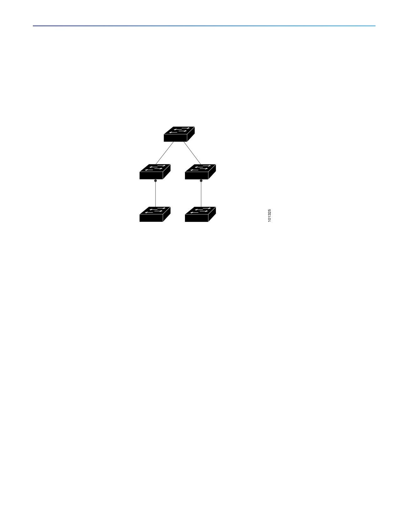
The cluster command switch in Figure 12 on page 99 belongs to VLANs 9 and 16. When new cluster-capable switches
join the cluster:
One cluster-capable switch and its access port are assigned to VLAN 9.
The other cluster-capable switch and its access port are assigned to management VLAN 16.
Figure 12
Discovery of Newly Installed Switches
Command device
VLAN 9
VLAN 16
Device A
Device B
AP
AP
VLAN 9
VLAN 16
New (out-of-box)
New (out-of-box)
candidate device
candidate device
IP Addresses
You must assign IP information to a cluster command switch. You can assign more than one IP address to the cluster
command switch, and you can access the cluster through any of the command-switch IP addresses. If you configure a
cluster standby group, you must use the standby-group virtual IP address to manage the cluster from the active cluster
command switch. Using the virtual IP address ensures that you retain connectivity to the cluster if the active cluster
command switch fails and that a standby cluster command switch becomes the active cluster command switch.
If the active cluster command switch fails and the standby cluster command switch takes over, you must either use the
standby-group virtual IP address or any of the IP addresses available on the new active cluster command switch to
access the cluster.
You can assign an IP address to a cluster-capable switch, but it is not necessary. A cluster member switch is managed
and communicates with other cluster member switches through the command-switch IP address. If the cluster member
switch leaves the cluster and it does not have its own IP address, you must assign an IP address to manage it as a
standalone switch.
For more information about IP addresses, see Performing Switch Setup Configuration, page 59
Hostnames
You do not need to assign a hostname to either a cluster command switch or an eligible cluster member. However, a
hostname assigned to the cluster command switch can help to identify the switch cluster. The default hostname for the
switch is Switch.
If a switch joins a cluster and it does not have a hostname, the cluster command switch appends a unique member
number to its own hostname and assigns it sequentially as each switch joins the cluster. The number means the order in
which the switch was added to the cluster. For example, a cluster command switch named eng-cluster could name the
fifth cluster member eng-cluster-5.
If a switch has a hostname, it retains that name when it joins a cluster and when it leaves the cluster.
99
Configuring Switch Clusters
How to Plan for Switch Clustering
If a switch received its hostname from the cluster command switch, was removed from a cluster, was then added to a
new cluster, and kept the same member number (such as 5), the switch overwrites the old hostname (such as
eng-cluster-5) with the hostname of the cluster command switch in the new cluster (such as mkg-cluster-5). If the
switch member number changes in the new cluster (such as 3), the switch retains the previous name (eng-cluster-5).
Passwords
You do not need to assign passwords to an individual switch if it will be a cluster member. When a switch joins a cluster,
it inherits the command-switch password and retains it when it leaves the cluster. If no command-switch password is
configured, the cluster member switch inherits a null password. Cluster member switches only inherit the
command-switch password.
If you change the member-switch password to be different from the command-switch password and save the change,
the switch is not manageable by the cluster command switch until you change the member-switch password to match
the command-switch password. Rebooting the member switch does not revert the password back to the
command-switch password. We recommend that you do not change the member-switch password after it joins a
cluster.
For more information about passwords, see Prevention for Unauthorized Switch Access, page 143.
For password considerations specific to the Catalyst 1900 and Catalyst 2820 switches, refer to the installation and
configuration guides for those switches.
SNMP Community Strings
A cluster member switch inherits the command-switch first read-only (RO) and read-write (RW) community strings with
@esN appended to the community strings:
command-switch-readonly-community-string@esN, where N is the member-switch number.
command-switch-readwrite-community-string@esN, where N is the member-switch number.
If the cluster command switch has multiple read-only or read-write community strings, only the first read-only and
read-write strings are propagated to the cluster member switch.
The switches support an unlimited number of community strings and string lengths. For more information about SNMP
and community strings, see Configuring SNMP, page 557
For SNMP considerations specific to the Catalyst 1900 and Catalyst 2820 switches, refer to the installation and
configuration guides specific to those switches.
TACACS+ and RADIUS
If TACACS+ is configured on a cluster member, it must be configured on all cluster members. Similarly, if RADIUS is
configured on a cluster member, it must be configured on all cluster members.The same switch cluster cannot have some
members configured with TACACS+ and other members configured with RADIUS.
For more information about TACACS+, see Switch Access with TACACS+, page 145. For more information about
RADIUS, see Configuring Radius Server Communication, page 172.
LRE Profiles
A configuration conflict occurs if a switch cluster has Long-Reach Ethernet (LRE) switches that use both private and
public profiles. If one LRE switch in a cluster is assigned a public profile, all LRE switches in that cluster must have that
same public profile. Before you add an LRE switch to a cluster, make sure that you assign it the same public profile used
by other LRE switches in the cluster.
A cluster can have a mix of LRE switches that use different private profiles.
100
Configuring Switch Clusters
Managing Switch Clusters
Managing Switch Clusters
Using the CLI to Manage Switch Clusters
You can configure cluster member switches from the CLI by first logging into the cluster command switch. Enter the
rcommand user EXEC command and the cluster member switch number to start a Telnet session (through a console or
Telnet connection) and to access the cluster member switch CLI. The command mode changes, and the Cisco IOS
commands operate as usual. Enter the exit privileged EXEC command on the cluster member switch to return to the
command-switch CLI.
This example shows how to log into member-switch 3 from the command-switch CLI:
switch# rcommand 3
If you do not know the member-switch number, enter the show cluster members privileged EXEC command on the
cluster command switch.
The Telnet session accesses the member-switch CLI at the same privilege level as on the cluster command switch. The
Cisco IOS commands then operate as usual.
Catalyst 1900 and Catalyst 2820 CLI Considerations
If your switch cluster has Catalyst 1900 and Catalyst 2820 switches running standard edition software, the Telnet session
accesses the management console (a menu-driven interface) if the cluster command switch is at privilege level 15. If the
cluster command switch is at privilege level 1 to 14, you are prompted for the password to access the menu console.
Command-switch privilege levels map to the Catalyst 1900 and Catalyst 2820 cluster member switches running
standard and Enterprise Edition Software as follows:
If the command-switch privilege level is 1 to 14, the cluster member switch is accessed at privilege level 1.
If the command-switch privilege level is 15, the cluster member switch is accessed at privilege level 15.
Note: The Catalyst 1900 and Catalyst 2820 CLI is available only on switches running Enterprise Edition Software.
For more information about the Catalyst 1900 and Catalyst 2820 switches, refer to the installation and configuration
guides for those switches.
Using SNMP to Manage Switch Clusters
When you first power on the switch, SNMP is enabled if you enter the IP information by using the setup program and
accept its proposed configuration.
When you create a cluster, the cluster command switch manages the exchange of messages between cluster member
switches and an SNMP application. The cluster software on the cluster command switch appends the cluster member
switch number (@esN, where N is the switch number) to the first configured read-write and read-only community strings
on the cluster command switch and propagates them to the cluster member switch. The cluster command switch uses
this community string to control the forwarding of gets, sets, and get-next messages between the SNMP management
station and the cluster member switches.
Note: When a cluster standby group is configured, the cluster command switch can change without your knowledge. Use
the first read-write and read-only community strings to communicate with the cluster command switch if there is a
cluster standby group configured for the cluster.
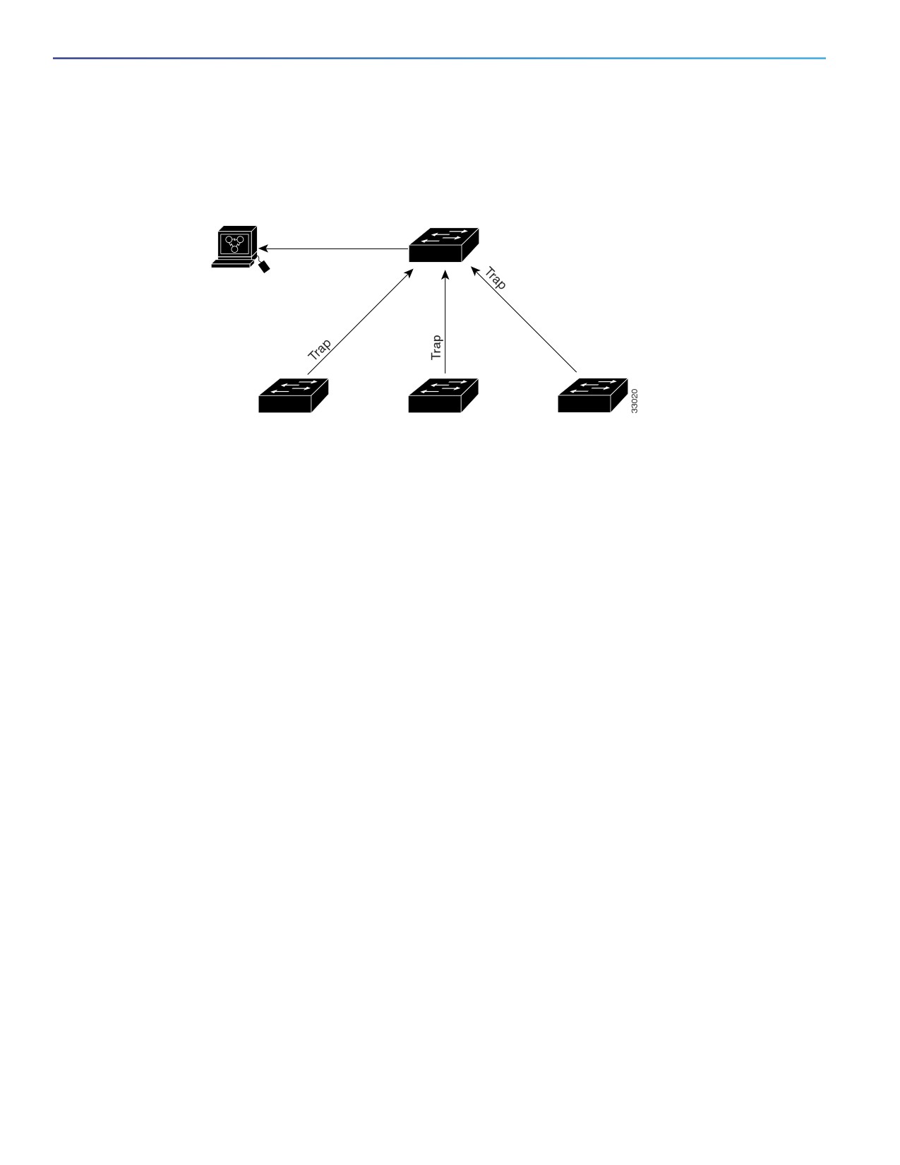
If the cluster member switch does not have an IP address, the cluster command switch redirects traps from the cluster
member switch to the management station, as shown in Figure 13 on page 102. If a cluster member switch has its own
IP address and community strings, the cluster member switch can send traps directly to the management station, without
going through the cluster command switch.
101
Configuring Switch Clusters
Additional References
If a cluster member switch has its own IP address and community strings, they can be used in addition to the access
provided by the cluster command switch.
Figure 13
SNMP Management for a Cluster
SNMP Manager
Command switch
Trap 1, Trap 2, Trap 3
Member 1
Member 2
Member 3
Additional References
The following sections provide references related to switch administration:
102

Configuring Switch Clusters
Additional References
Related Documents
Related Topic
Document Title
Cisco IOS basic commands
Cisco IOS Configuration Fundamentals Command Reference
Standards
Standards
Title
No new or modified standards are supported by this
—
feature, and support for existing standards has not
been modified by this feature.
MIBs
MIBs
MIBs Link
—
To locate and download MIBs using Cisco IOS XR software, use the
Cisco MIB Locator found at the following URL and choose a platform
under the Cisco Access Products menu:
RFCs
RFCs
Title
No new or modified RFCs are supported by this
—
feature, and support for existing RFCs has not been
modified by this feature.
Technical Assistance
Description
Link
The Cisco Technical Support website contains
thousands of pages of searchable technical content,
including links to products, technologies, solutions,
technical tips, and tools. Registered Cisco.com users
can log in from this page to access even more content.
103
Configuring Switch Clusters
Additional References
104
Performing Switch Administration
This chapter describes how to perform one-time operations to administer your switch.
Information About Performing Switch Administration
System Time and Date Management
You can manage the system time and date on your switch using automatic configuration, such as the Network Time
Protocol (NTP), or manual configuration methods.
System Clock
The basis of time service is the system clock. This clock runs from the moment the system starts up and keeps track of
the date and time.
The system clock can then be set from these sources:
NTP
Manual configuration
The system clock can provide time to these services:
User show commands
Logging and debugging messages
The system clock keeps track of time internally based on Universal Time Coordinated (UTC), also known as Greenwich
Mean Time (GMT). You can configure information about the local time zone and summer time (daylight saving time) so
that the time appears correctly for the local time zone.
The system clock keeps track of whether the time is authoritative or not (that is, whether it has been set by a time source
considered to be authoritative). If it is not authoritative, the time is available only for display purposes and is not
redistributed. For configuration information, see Configuring Time and Date Manually, page 111.
Network Time Protocol
NTP is designed to time-synchronize a network of devices. NTP runs over User Datagram Protocol (UDP), which runs
over IP. NTP is documented in RFC 1305.
An NTP network usually gets its time from an authoritative time source, such as a radio clock or an atomic clock attached
to a time server. NTP then distributes this time across the network. NTP is extremely efficient; no more than one packet
per minute is necessary to synchronize two devices to within a millisecond of one another.
NTP uses the concept of a stratum to describe how many NTP hops away a device is from an authoritative time source.
A stratum 1 time server has a radio or atomic clock directly attached, a stratum 2 time server receives its time through
NTP from a stratum 1 time server, and so on. A device running NTP automatically chooses as its time source the device
with the lowest stratum number with which it communicates through NTP. This strategy effectively builds a
self-organizing tree of NTP speakers.
105
Performing Switch Administration
Information About Performing Switch Administration
NTP avoids synchronizing to a device whose time might not be accurate by never synchronizing to a device that is not
synchronized. NTP also compares the time reported by several devices and does not synchronize to a device whose time
is significantly different than the others, even if its stratum is lower.
The communications between devices running NTP (known as associations) are usually statically configured; each device
is given the IP address of all devices with which it should form associations. Accurate timekeeping is possible by
exchanging NTP messages between each pair of devices with an association. However, in a LAN environment, NTP can
be configured to use IP broadcast messages instead. This alternative reduces configuration complexity because each
device can simply be configured to send or receive broadcast messages. However, in that case, information flow is
one-way only.
The time kept on a device is a critical resource; you should use the security features of NTP to avoid the accidental or
malicious setting of an incorrect time. Two mechanisms are available: an access list-based restriction scheme and an
encrypted authentication mechanism.
Cisco’s implementation of NTP does not support stratum 1 service; it is not possible to connect to a radio or atomic clock.
We recommend that the time service for your network be derived from the public NTP servers available on the IP Internet.
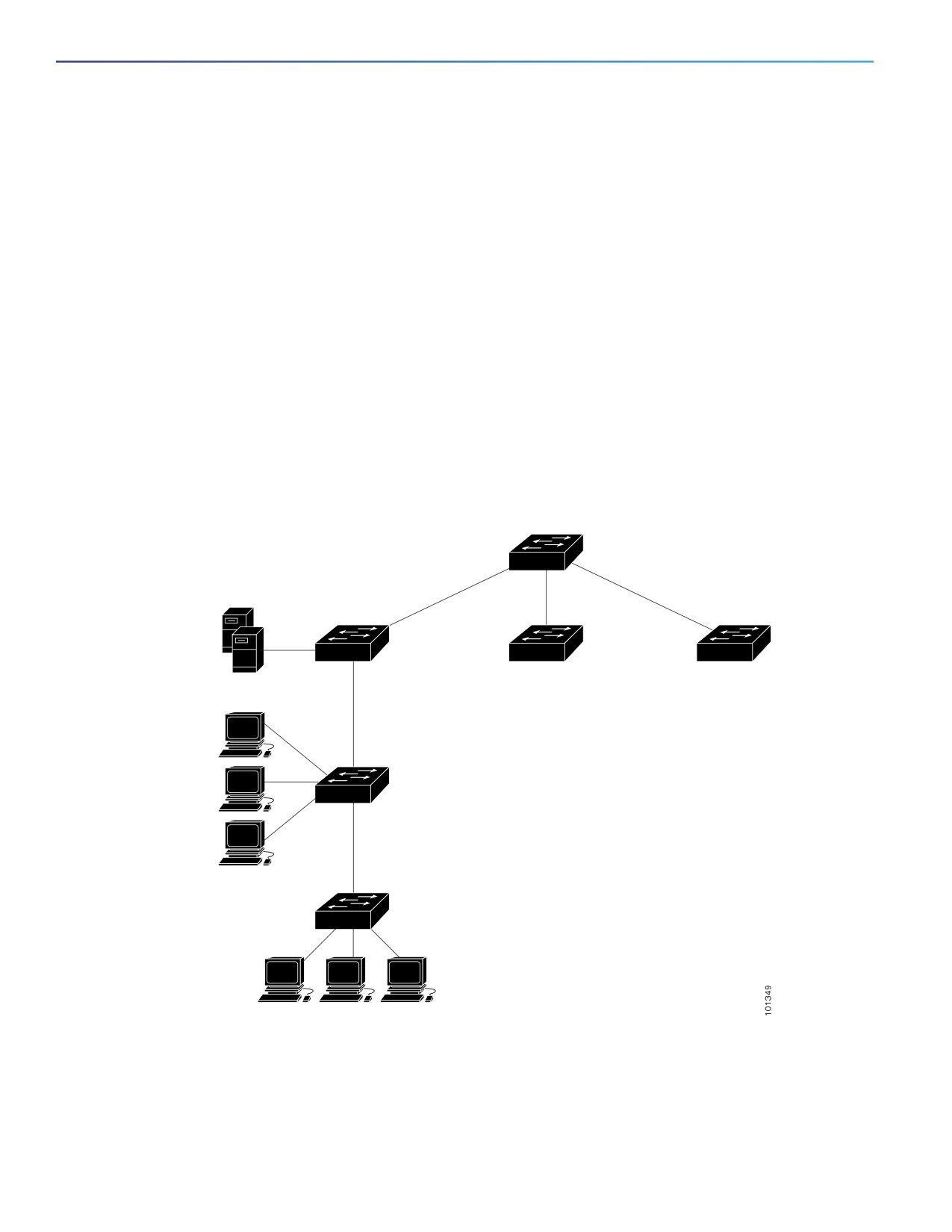
Figure 14 on page 106 shows a typical network example using NTP. Switch A is the NTP master, with Switches B, C, and
D configured in NTP server mode, in server association with Switch A. Switch E is configured as an NTP peer to the
upstream and downstream switches, Switch B and Switch F.
Figure 14
Typical NTP Network Configuration
Switch A
Local
workgroup
servers
Switch B
Switch C
Switch D
Switch E
Workstations
Switch F
Workstations
If the network is isolated from the Internet, Cisco’s implementation of NTP allows a device to act as if it is synchronized
through NTP, when in fact it has learned the time by using other means. Other devices then synchronize to that device
through NTP.
106

Performing Switch Administration
Information About Performing Switch Administration
When multiple sources of time are available, NTP is always considered to be more authoritative. NTP time overrides the
time set by any other method.
Several manufacturers include NTP software for their host systems, and a publicly available version for systems running
UNIX and its various derivatives is also available. This software allows host systems to be time-synchronized as well.
NTP Version 4
NTP version 4 is implemented on the switch. NTPv4 is an extension of NTP version 3. NTPv4 supports both IPv4 and IPv6
and is backward-compatible with NTPv3.
NTPv4 provides these capabilities:
Support for IPv6.
Improved security compared to NTPv3. The NTPv4 protocol provides a security framework based on public key
cryptography and standard X509 certificates.
Automatic calculation of the time-distribution hierarchy for a network. Using specific multicast groups, NTPv4
automatically configures the hierarchy of the servers to achieve the best time accuracy for the lowest bandwidth
cost. This feature leverages site-local IPv6 multicast addresses.
For details about configuring NTPv4, see Cisco IOS IPv6 Configuration Guide on Cisco.com.
DNS
The DNS protocol controls the Domain Name System (DNS), a distributed database with which you can map hostnames
to IP addresses. When you configure DNS on your switch, you can substitute the hostname for the IP address with all IP
commands, such as ping, telnet, connect, and related Telnet support operations.
IP defines a hierarchical naming scheme that allows a device to be identified by its location or domain. Domain names
are pieced together with periods (.) as the delimiting characters. For example, Cisco Systems is a commercial
organization that IP identifies by a com domain name, so its domain name is cisco.com. A specific device in this domain,
for example, the File Transfer Protocol (FTP) system is identified as ftp.cisco.com.
To keep track of domain names, IP has defined the concept of a domain name server, which holds a cache (or database)
of names mapped to IP addresses. To map domain names to IP addresses, you must first identify the hostnames, specify
the name server that is present on your network, and enable the DNS.
Default DNS Configuration
Feature
Default Setting
DNS enable state
Enabled.
DNS default domain name
None configured.
DNS servers
No name server addresses are configured.
Login Banners
You can configure a message-of-the-day (MOTD) and a login banner. The MOTD banner displays on all connected
terminals at login and is useful for sending messages that affect all network users (such as impending system
shutdowns).
The login banner also displays on all connected terminals. It appears after the MOTD banner and before the login
prompts.
107
Performing Switch Administration
Information About Performing Switch Administration
The MOTD and login banners are not configured.
System Name and Prompt
You configure the system name on the switch to identify it. By default, the system name and prompt are Switch.
If you have not configured a system prompt, the first 20 characters of the system name are used as the system prompt.
A greater-than symbol [>] is appended. The prompt is updated whenever the system name changes.
MAC Address Table
The MAC address table contains address information that the switch uses to forward traffic between ports. All MAC
addresses in the address table are associated with one or more ports. The address table includes these types of
addresses:
Dynamic address—A source MAC address that the switch learns and then ages when it is not in use.
Static address—A manually entered unicast address that does not age and that is not lost when the switch resets.
The address table lists the destination MAC address, the associated VLAN ID, and port number associated with the
address and the type (static or dynamic).
Address Table
With multiple MAC addresses supported on all ports, you can connect any port on the switch to individual workstations,
repeaters, switches, routers, or other network devices. The switch provides dynamic addressing by learning the source
address of packets it receives on each port and adding the address and its associated port number to the address table.
As stations are added or removed from the network, the switch updates the address table, adding new dynamic
addresses and aging out those that are not in use.
The aging interval is globally configured. However, the switch maintains an address table for each VLAN, and STP can
accelerate the aging interval on a per-VLAN basis.
The switch sends packets between any combination of ports, based on the destination address of the received packet.
Using the MAC address table, the switch forwards the packet only to the port associated with the destination address.
If the destination address is on the port that sent the packet, the packet is filtered and not forwarded. The switch always
uses the store-and-forward method: complete packets are stored and checked for errors before transmission.
MAC Addresses and VLANs
All addresses are associated with a VLAN. An address can exist in more than one VLAN and have different destinations
in each. Unicast addresses, for example, could be forwarded to port 1 in VLAN 1 and ports 9, 10, and 1 in VLAN 5.
Each VLAN maintains its own logical address table. A known address in one VLAN is unknown in another until it is learned
or statically associated with a port in the other VLAN.
When private VLANs are configured, address learning depends on the type of MAC address:
Dynamic MAC addresses learned in one VLAN of a private VLAN are replicated in the associated VLANs. For
example, a MAC address learned in a private-VLAN secondary VLAN is replicated in the primary VLAN.
Static MAC addresses configured in a primary or secondary VLAN are not replicated in the associated VLANs. When
you configure a static MAC address in a private VLAN primary or secondary VLAN, you should also configure the
same static MAC address in all associated VLANs.
108

Performing Switch Administration
Information About Performing Switch Administration
Default MAC Address Table Configuration
Feature
Default Setting
Aging time
300 seconds
Dynamic addresses
Automatically learned
Static addresses
None configured
Address Aging Time for VLANs
Dynamic addresses are source MAC addresses that the switch learns and then ages when they are not in use. You can
change the aging time setting for all VLANs or for a specified VLAN.
Setting too short an aging time can cause addresses to be prematurely removed from the table. Then when the switch
receives a packet for an unknown destination, it floods the packet to all ports in the same VLAN as the receiving port.
This unnecessary flooding can impact performance. Setting too long an aging time can cause the address table to be
filled with unused addresses, which prevents new addresses from being learned. Flooding results, which can impact
switch performance.
MAC Address Change Notification Traps
MAC address change notification tracks users on a network by storing the MAC address change activity. When the switch
learns or removes a MAC address, an SNMP notification trap can be sent to the NMS. If you have many users coming
and going from the network, you can set a trap-interval time to bundle the notification traps to reduce network traffic.
The MAC notification history table stores MAC address activity for each port for which the trap is set. MAC address
change notifications are generated for dynamic and secure MAC addresses. Notifications are not generated for self
addresses, multicast addresses, or other static addresses.
Static Addresses
A static address has these characteristics:
Is manually entered in the address table and must be manually removed.
Can be a unicast or multicast address.
Does not age and is retained when the switch restarts.
You can add and remove static addresses and define the forwarding behavior for them. The forwarding behavior defines
how a port that receives a packet forwards it to another port for transmission. Because all ports are associated with at
least one VLAN, the switch acquires the VLAN ID for the address from the ports that you specify. You can specify a
different list of destination ports for each source port.
A packet with a static address that arrives on a VLAN where it has not been statically entered is flooded to all ports and
not learned.
You add a static address to the address table by specifying the destination MAC unicast address and the VLAN from
which it is received. Packets received with this destination address are forwarded to the interface specified with the
interface-id option.
When you configure a static MAC address in a private-VLAN primary or secondary VLAN, you should also configure the
same static MAC address in all associated VLANs. Static MAC addresses configured in a private-VLAN primary or
secondary VLAN are not replicated in the associated VLAN.
109
Performing Switch Administration
Information About Performing Switch Administration
Unicast MAC Address Filtering
When unicast MAC address filtering is enabled, the switch drops packets with specific source or destination MAC
addresses. This feature is disabled by default and only supports unicast static addresses.
Follow these guidelines when using this feature:
Multicast MAC addresses, broadcast MAC addresses, and router MAC addresses are not supported. If you specify
one of these addresses when entering the mac address-table static mac-addr vlan vlan-id drop global
configuration command, one of these messages appears:
% Only unicast addresses can be configured to be dropped
% CPU destined address cannot be configured as drop address
Packets that are forwarded to the CPU are also not supported.
If you add a unicast MAC address as a static address and configure unicast MAC address filtering, the switch either
adds the MAC address as a static address or drops packets with that MAC address, depending on which command
was entered last. The second command that you entered overrides the first command.
For example, if you enter the mac address-table static mac-addr vlan vlan-id interface interface-id global
configuration command followed by the mac address-table static mac-addr vlan vlan-id drop command, the
switch drops packets with the specified MAC address as a source or destination.
If you enter the mac address-table static mac-addr vlan vlan-id drop global configuration command followed by
the mac address-table static mac-addr vlan vlan-id interface interface-id command, the switch adds the MAC
address as a static address.
You enable unicast MAC address filtering and configure the switch to drop packets with a specific address by specifying
the source or destination unicast MAC address and the VLAN from which it is received.
MAC Address Learning on a VLAN
By default, MAC address learning is enabled on all VLANs on the switch. You can control MAC address learning on a
VLAN to manage the available MAC address table space by controlling which VLANs, and therefore which ports, can
learn MAC addresses. Before you disable MAC address learning, be sure that you are familiar with the network topology
and the switch system configuration. Disabling MAC address learning on a VLAN could cause flooding in the network.
Follow these guidelines when disabling MAC address learning on a VLAN:
Use caution before disabling MAC address learning on a VLAN with a configured switch virtual interface (SVI). The
switch then floods all IP packets in the Layer 2 domain.
You can disable MAC address learning on a single VLAN ID (for example, no mac address-table learning vlan 223)
or on a range of VLAN IDs (for example, no mac address-table learning vlan 1-20, 15).
We recommend that you disable MAC address learning only in VLANs with two ports. If you disable MAC address
learning on a VLAN with more than two ports, every packet entering the switch is flooded in that VLAN domain.
You cannot disable MAC address learning on a VLAN that is used internally by the switch. If the VLAN ID that you
enter is an internal VLAN, the switch generates an error message and rejects the command. To view internal VLANs
in use, enter the show vlan internal usage privileged EXEC command.
If you disable MAC address learning on a VLAN configured as a private-VLAN primary VLAN, MAC addresses are
still learned on the secondary VLAN that belongs to the private VLAN and are then replicated on the primary VLAN.
If you disable MAC address learning on the secondary VLAN, but not the primary VLAN of a private VLAN, MAC
address learning occurs on the primary VLAN and is replicated on the secondary VLAN.
You cannot disable MAC address learning on an RSPAN VLAN. The configuration is not allowed.
110
Performing Switch Administration
How to Perform Switch Administration
If you disable MAC address learning on a VLAN that includes a secure port, MAC address learning is not disabled
on that port. If you disable port security, the configured MAC address learning state is enabled.
To reenable MAC address learning on a VLAN, use the default mac address-table learning vlan vlan-id global
configuration command. You can also reenable MAC address learning on a VLAN by entering the mac address-table
learning vlan vlan-id global configuration command. The first (default) command returns to a default condition and
therefore does not appear in the output from the show running-config command. The second command causes the
configuration to appear in the show running-config privileged EXEC command display.
ARP Table Management
To communicate with a device (over Ethernet, for example), the software first must learn the 48-bit MAC address or the
local data link address of that device. The process of learning the local data link address from an IP address is called
address resolution.
The Address Resolution Protocol (ARP) associates a host IP address with the corresponding media or MAC addresses
and the VLAN ID. Using an IP address, ARP finds the associated MAC address. When a MAC address is found, the
IP-MAC address association is stored in an ARP cache for rapid retrieval. Then the IP datagram is encapsulated in a
link-layer frame and sent over the network. Encapsulation of IP datagrams and ARP requests and replies on IEEE 802
networks other than Ethernet is specified by the Subnetwork Access Protocol (SNAP). By default, standard Ethernet-style
ARP encapsulation (represented by the arpa keyword) is enabled on the IP interface.
ARP entries added manually to the table do not age and must be manually removed.
How to Perform Switch Administration
Configuring Time and Date Manually
If no other source of time is available, you can manually configure the time and date after the system is restarted. The
time remains accurate until the next system restart. We recommend that you use manual configuration only as a last
resort. If you have an outside source to which the switch can synchronize, you do not need to manually set the system
clock.
Setting the System Clock
If you have an outside source on the network that provides time services, such as an NTP server, you do not need to
manually set the system clock.
Beginning in privileged EXEC mode, follow these steps to set the system clock:
Command
Purpose
1.
clock set hh:mm:ss day month year
Manually sets the system clock using one of these formats:
or
hh:mm:ss—Specifies the time in hours (24-hour format), minutes, and
seconds. The time specified is relative to the configured time zone.
clock set hh:mm:ss month day year
day—Specifies the day by date in the month.
month—Specifies the month by name.
year—Specifies the year (no abbreviation).
111

Performing Switch Administration
How to Perform Switch Administration
Configuring the Time Zone
The minutes-offset variable in the clock timezone global configuration command is available for those cases where a
local time zone is a percentage of an hour different from UTC. For example, the time zone for some sections of Atlantic
Canada (AST) is UTC-3.5, where the 3 means 3 hours and .5 means 50 percent. In this case, the necessary command
is clock timezone AST -3 30.
Command
Purpose
1.
configure terminal
Enters global configuration mode.
2.
clock timezone zone hours-offset
Sets the time zone.
[minutes-offset]
The switch keeps internal time in universal time coordinated (UTC), so this
command is used only for display purposes and when the time is
manually set.
zone—Enters the name of the time zone to be displayed when
standard time is in effect. The default is UTC.
hours-offset—Enters the hours offset from UTC.
(Optional) minutes-offset—Enters the minutes offset from UTC.
3.
end
Returns to privileged EXEC mode.
Configuring Summer Time (Daylight Saving Time)
To configure summer time (daylight saving time) in areas where it starts and ends on a particular day of the week each
year, perform this task:
Command
Purpose
1.
configure terminal
Enters global configuration mode.
2.
clock summer-time zone recurring
Configures summer time to start and end on the specified days every
[week day month hh:mm week day
year.
month hh:mm [offset]]
Summer time is disabled by default. If you specify clock summer-time
zone recurring without parameters, the summer time rules default to the
United States rules.
zone—Specifies the name of the time zone (for example, PDT) to be
displayed when summer time is in effect.
(Optional) week—Specifies the week of the month (1 to 5 or last).
(Optional) day—Specifies the day of the week (Sunday, Monday...).
(Optional) month—Specifies the month (January, February...).
(Optional) hh:mm—Specifies the time (24-hour format) in hours and
minutes.
(Optional) offset—Specifies the number of minutes to add during
summer time. The default is 60.
3.
end
Returns to privileged EXEC mode.
112

Performing Switch Administration
How to Perform Switch Administration
Configuring Summer Time (Exact Date and Time)
To configure summer time when it does not follow a recurring pattern (configure the exact date and time of the next
summer time events), perform this task:
Command
Purpose
1.
configure terminal
Enters global configuration mode.
2.
clock summer-time zone date [month
Configures summer time to start on the first date and end on the second
date year hh:mm month date year
date.
hh:mm [offset]]
Summer time is disabled by default.
or
zone—Specifies the name of the time zone (for example, PDT) to be
clock summer-time zone date [date
displayed when summer time is in effect.
month year hh:mm date month year
hh:mm [offset]]
(Optional) week—Specifies the week of the month (1 to 5 or last).
(Optional) day—Specifies the day of the week (Sunday, Monday...).
(Optional) month—Specifies the month (January, February...).
(Optional) hh:mm—Specifies the time (24-hour format) in hours and
minutes.
(Optional) offset—Specifies the number of minutes to add during
summer time. The default is 60.
3.
end
Returns to privileged EXEC mode.
Configuring a System Name
Command
Purpose
1.
configure terminal
Enters global configuration mode.
2.
hostname name
Manually configures a system name.
The default setting is switch.
The name must follow the rules for ARPANET hostnames. They must start
with a letter, end with a letter or digit, and have as interior characters only
letters, digits, and hyphens. Names can be up to 63 characters.
3.
end
Returns to privileged EXEC mode.
Setting Up DNS
If you use the switch IP address as its hostname, the IP address is used and no DNS query occurs. If you configure a
hostname that contains no periods (.), a period followed by the default domain name is appended to the hostname before
the DNS query is made to map the name to an IP address. The default domain name is the value set by the ip
domain-name global configuration command. If there is a period (.) in the hostname, the Cisco IOS software looks up
the IP address without appending any default domain name to the hostname.
113

Performing Switch Administration
How to Perform Switch Administration
Command
Purpose
1.
configure terminal
Enters global configuration mode.
2.
ip domain-name name
Defines a default domain name that the software uses to complete unqualified
hostnames (names without a dotted-decimal domain name).
Do not include the initial period that separates an unqualified name from the
domain name.
At boot-up time, no domain name is configured; however, if the switch
configuration comes from a BOOTP or Dynamic Host Configuration Protocol
(DHCP) server, then the default domain name might be set by the BOOTP or
DHCP server (if the servers were configured with this information).
3.
ip name-server server-address1
Specifies the address of one or more name servers to use for name and address
[server-address2 ...
resolution.
server-address6]
You can specify up to six name servers. Separate each server address with a
space. The first server specified is the primary server. The switch sends DNS
queries to the primary server first. If that query fails, the backup servers are
queried.
4.
ip domain-lookup
(Optional) Enables DNS-based hostname-to-address translation on your
switch. This feature is enabled by default.
If your network devices require connectivity with devices in networks for which
you do not control name assignment, you can dynamically assign device names
that uniquely identify your devices by using the global Internet naming scheme
(DNS).
5.
end
Returns to privileged EXEC mode.
Configuring Login Banners
Configuring a Message-of-the-Day Login Banner
You can create a single or multiline message banner that appears on the screen when someone logs in to the switch.
Command
Purpose
1.
configure terminal
Enters global configuration mode.
2.
banner motd c message c
Specifies the message of the day.
c—Enters the delimiting character of your choice, for example, a
pound sign (#), and press the Return key. The delimiting character
signifies the beginning and end of the banner text. Characters after
the ending delimiter are discarded.
message—Enters a banner message up to 255 characters. You
cannot use the delimiting character in the message.
3.
end
Returns to privileged EXEC mode.
Configuring a Login Banner
You can configure a login banner to be displayed on all connected terminals. This banner appears after the MOTD banner
and before the login prompt.
114

Performing Switch Administration
How to Perform Switch Administration
Command
Purpose
1.
configure terminal
Enters global configuration mode.
2.
banner login c message c
Specifies the login message.
c—Enters the delimiting character of your choice, for example, a pound
sign (#), and press the Return key. The delimiting character signifies the
beginning and end of the banner text. Characters after the ending
delimiter are discarded.
message—Enters a login message up to 255 characters. You cannot use
the delimiting character in the message.
3.
end
Returns to privileged EXEC mode.
Managing the MAC Address Table
Changing the Address Aging Time
Command
Purpose
1.
configure terminal
Enters global configuration mode.
2.
mac address-table aging-time [0 |
Sets the length of time that a dynamic entry remains in the MAC
10-1000000] [vlan vlan-id]
address table after the entry is used or updated.
The range is 10 to 1000000 seconds. The default is 300. You can
also enter 0, which disables aging. Static address entries are never
aged or removed from the table.
vlan-id—Valid IDs are 1 to 4096.
3.
end
Returns to privileged EXEC mode.
115

Performing Switch Administration
How to Perform Switch Administration
Configuring MAC Address Change Notification Traps
Command
Purpose
1.
configure terminal
Enters global configuration mode.
2.
snmp-server host host-addr {traps | informs} {version {1 |
Specifies the recipient of the trap message.
2c | 3}} community-string notification-type
host-addr—Specifies the name or address of the
NMS.
traps (the default)—Sends SNMP traps to the
host.
informs—Sends SNMP informs to the host.
Specifies the SNMP version to support. Version
1, the default, is not available with informs.
community-string—Specifies the string to send
with the notification operation. You can set this
string by using the snmp-server host
command, but we recommend that you define
this string by using the snmp-server
community command before using the
snmp-server host command.
notification-type—Uses the mac-notification
keyword.
3.
snmp-server enable traps mac-notification change
Enables the switch to send MAC address change
notification traps to the NMS.
4.
mac address-table notification change
Enables the MAC address change notification
feature.
5.
mac address-table notification change [interval value]
Enters the trap interval time and the history table
[history-size value]
size.
(Optional) interval value—Specifies the
notification trap interval in seconds between
each set of traps that are generated to the NMS.
The range is 0 to 2147483647 seconds; the
default is 1 second.
(Optional) history-size value—Specifies the
maximum number of entries in the MAC
notification history table. The range is 0 to 500;
the default is 1.
6.
interface interface-id
Enters interface configuration mode, and specifies
the Layer 2 interface on which to enable the SNMP
MAC address notification trap.
7.
snmp trap mac-notification change {added | removed}
Enables the MAC address change notification trap
on the interface.
Enables the trap when a MAC address is added
on this interface.
Enables the trap when a MAC address is
removed from this interface.
8.
end
Returns to privileged EXEC mode.
116

Performing Switch Administration
How to Perform Switch Administration
Configuring MAC Address Move Notification Traps
When you configure MAC-move notification, an SNMP notification is generated and sent to the network management
system whenever a MAC address moves from one port to another within the same VLAN.
Command
Purpose
1.
configure terminal
Enters global configuration mode.
2.
snmp-server host host-addr {traps | informs} {version {1 |
Specifies the recipient of the trap message.
2c | 3}} community-string notification-type
host-addr—Specifies the name or address of the
NMS.
traps (the default)—Sends SNMP traps to the
host.
informs—Sends SNMP informs to the host.
version—Specifies the SNMP version to
support. Version 1, the default, is not available
with informs.
community-string—Specifies the string to send
with the notification operation. You can set this
string by using the snmp-server host
command, but we recommend that you define
this string by using the snmp-server
community command before using the
snmp-server host command.
notification-type—Uses the mac-notification
keyword.
3.
snmp-server enable traps mac-notification move
Enables the switch to send MAC address move
notification traps to the NMS.
4.
mac address-table notification mac-move
Enables the MAC address move notification feature.
5.
end
Returns to privileged EXEC mode.
Configuring MAC Threshold Notification Traps
When you configure MAC threshold notification, an SNMP notification is generated and sent to the network management
system when a MAC address table threshold limit is reached or exceeded.
117

Performing Switch Administration
How to Perform Switch Administration
Command
Purpose
1.
configure terminal
Enters global configuration mode.
2.
snmp-server host host-addr {traps | informs} {version {1 |
Specifies the recipient of the trap message.
2c | 3}} community-string notification-type
host-addr—Specifies the name or address of the
NMS.
traps (the default)—Sends SNMP traps to the
host.
informs—Sends SNMP informs to the host.
version—Specifies the SNMP version to
support. Version 1, the default, is not available
with informs.
community-string—Specifies the string to send
with the notification operation. You can set this
string by using the snmp-server host
command, but we recommend that you define
this string by using the snmp-server
community command before using the
snmp-server host command.
notification-type—Uses the mac-notification
keyword.
3.
snmp-server enable traps mac-notification threshold
Enables the switch to send MAC threshold
notification traps to the NMS.
4.
mac address-table notification threshold
Enables the MAC address threshold notification
feature.
5.
mac address-table notification threshold [limit
Enters the threshold value for the MAC address
percentage] | [interval time]
threshold usage monitoring.
(Optional) limit percentage—Specifies the
percentage of the MAC address table use; valid
values are from 1 to 100 percent. The default is
50 percent.
(Optional) interval time—Specifies the time
between notifications; valid values are greater
than or equal to 120 seconds. The default is 120
seconds.
6.
end
Returns to privileged EXEC mode.
118

Performing Switch Administration
How to Perform Switch Administration
Adding and Removing Static Address Entries
Command
Purpose
1.
configure terminal
Enters global configuration mode.
2.
mac address-table static mac-addr
Adds a static address to the MAC address table.
vlan vlan-id interface interface-id
mac-addr—Specifies the destination MAC unicast address to add to
the address table. Packets with this destination address received in
the specified VLAN are forwarded to the specified interface.
vlan-id—Specifies the VLAN for which the packet with the specified
MAC address is received. Valid VLAN IDs are 1 to 4096.
interface-id—Specifies the interface to which the received packet is
forwarded. Valid interfaces include physical ports or port channels.
For static multicast addresses, you can enter multiple interface IDs.
For static unicast addresses, you can enter only one interface at a
time, but you can enter the command multiple times with the same
MAC address and VLAN ID.
3.
end
Returns to privileged EXEC mode.
Configuring Unicast MAC Address Filtering
Command
Purpose
1.
configure terminal
Enters global configuration mode.
2.
mac address-table static mac-addr
Enables unicast MAC address filtering and configures the switch to drop
vlan vlan-id drop
a packet with the specified source or destination unicast static address.
mac-addr—Specifies a source or destination unicast MAC address.
Packets with this MAC address are dropped.
vlan-id—Specifies the VLAN for which the packet with the specified
MAC address is received. Valid VLAN IDs are 1 to 4096.
3.
end
Returns to privileged EXEC mode.
Disabling MAC Address Learning on a VLAN
Command
Purpose
1.
configure terminal
Enters global configuration mode.
2.
no mac address-table learning vlan
Disables MAC address learning on the specified VLAN or VLANs. You can
vlan-id
specify a single VLAN ID or a range of VLAN IDs separated by a hyphen
or comma. Valid VLAN IDs are 1 to 4096.
3.
end
Returns to privileged EXEC mode.
119

Performing Switch Administration
Monitoring and Maintaining Switch Administration
Monitoring and Maintaining Switch Administration
Command
Purpose
clear mac address-table dynamic
Removes all dynamic entries.
clear mac address-table dynamic address mac-address
Removes a specific MAC address.
clear mac address-table dynamic interface interface-id
Removes all addresses on the specified physical port or port
channel.
clear mac address-table dynamic vlan vlan-id
Removes all addresses on a specified VLAN.
show clock [detail]
Displays the time and date configuration.
show ip igmp snooping groups
Displays the Layer 2 multicast entries for all VLANs or the
specified VLAN.
show mac address-table address
Displays MAC address table information for the specified
MAC address.
show mac address-table aging-time
Displays the aging time in all VLANs or the specified VLAN.
show mac address-table count
Displays the number of addresses present in all VLANs or the
specified VLAN.
show mac address-table dynamic
Displays only dynamic MAC address table entries.
show mac address-table interface
Displays the MAC address table information for the specified
interface.
show mac address-table learning
Displays MAC address learning status of all VLANs or the
specified VLAN.
show mac address-table notification
Displays the MAC notification parameters and history table.
show mac address-table static
Displays only static MAC address table entries.
show mac address-table vlan
Displays the MAC address table information for the specified
VLAN.
Configuration Examples for Performing Switch Admininistration
Setting the System Clock: Example
This example shows how to manually set the system clock to 1:32 p.m. on July 23, 2001:
Switch# clock set 13:32:00 23 July 2001
Configuring Summer Time: Examples
The first part of the clock summer-time global configuration command specifies when summer time begins, and the
second part specifies when it ends. All times are relative to the local time zone. The start time is relative to standard time.
The end time is relative to summer time. If the starting month is after the ending month, the system assumes that you are
in the southern hemisphere.
This example (for daylight savings time) shows how to specify that summer time starts on the first Sunday in April
at 02:00 and ends on the last Sunday in October at 02:00:
Switch(config)# clock summer-time PDT recurring 1 Sunday April 2:00 last Sunday October 2:00
This example shows how to set summer time to start on October 12, 2000, at 02:00, and end on April 26, 2001, at 02:00:
Switch(config)# clock summer-time pdt date 12 October 2000 2:00 26 April 2001 2:00
120
Performing Switch Administration
Configuration Examples for Performing Switch Admininistration
Configuring a MOTD Banner: Examples
This example shows how to configure a MOTD banner for the switch by using the pound sign (#) symbol as the beginning
and ending delimiter:
Switch(config)# banner motd #
This is a secure site. Only authorized users are allowed.
For access, contact technical support.
#
Switch(config)#
This example shows the banner that appears from the previous configuration:
Unix> telnet 172.2.5.4
Trying 172.2.5.4...
Connected to 172.2.5.4.
Escape character is '^]'.
This is a secure site. Only authorized users are allowed.
For access, contact technical support.
User Access Verification
Password:
Configuring a Login Banner: Example
This example shows how to configure a login banner for the switch by using the dollar sign ($) symbol as the beginning
and ending delimiter:
Switch(config)# banner login $
Access for authorized users only. Please enter your username and password.
$
Switch(config)#
Configuring MAC Address Change Notification Traps: Example
This example shows how to specify 172.20.10.10 as the NMS, enable the switch to send MAC address notification traps
to the NMS, enable the MAC address-change notification feature, set the interval time to 123 seconds, set the
history-size to 100 entries, and enable traps whenever a MAC address is added on the specified port.
Switch(config)# snmp-server host 172.20.10.10 traps private mac-notification
Switch(config)# snmp-server enable traps mac-notification change
Switch(config)# mac address-table notification change
Switch(config)# mac address-table notification change interval 123
Switch(config)# mac address-table notification change history-size 100
Switch(config)# interface GigabitEthernet1/18
Switch(config-if)# snmp trap mac-notification change added
Sending MAC Address Move Notification Traps: Example
This example shows how to specify 172.20.10.10 as the NMS, enable the switch to send MAC address move notification
traps to the NMS, enable the MAC address move notification feature, and enable traps when a MAC address moves from
one port to another.
Switch(config)# snmp-server host 172.20.10.10 traps private mac-notification
Switch(config)# snmp-server enable traps mac-notification move
Switch(config)# mac address-table notification mac-move
121
Performing Switch Administration
Additional References
Configuring MAC Threshold Notification Traps: Example
This example shows how to specify 172.20.10.10 as the NMS, enable the MAC address threshold notification feature,
set the interval time to 123 seconds, and set the limit to 78 per cent.
Switch(config)# snmp-server host 172.20.10.10 traps private mac-notification
Switch(config)# snmp-server enable traps mac-notification threshold
Switch(config)# mac address-table notification threshold
Switch(config)# mac address-table notification threshold interval 123
Switch(config)# mac address-table notification threshold limit 78
Adding the Static Address to the MAC Address Table: Example
This example shows how to add the static address c2f3.220a.12f4 to the MAC address table. When a packet is received
in VLAN 4 with this MAC address as its destination address, the packet is forwarded to the specified port:
Switch(config)# mac address-table static c2f3.220a.12f4 vlan 4 interface GigabitEthernet1/17
Configuring Unicast MAC Address Filtering: Example
This example shows how to enable unicast MAC address filtering and to configure the switch to drop packets that have
a source or destination address of c2f3.220a.12f4. When a packet is received in VLAN 4 with this MAC address as its
source or destination, the packet is dropped:
Switch(config)# mac address-table static c2f3.220a.12f4 vlan 4 drop
Additional References
The following sections provide references related to switch administration:
122

Performing Switch Administration
Additional References
Related Documents
Related Topic
Document Title
Cisco IOS basic commands
Cisco IOS Configuration Fundamentals Command Reference
Cisco IOS routing commands.
Cisco IOS IP Command Reference, Volume 2 of 3: Routing Protocols
Standards
Standards
Title
No new or modified standards are supported by this
—
feature, and support for existing standards has not
been modified by this feature.
MIBs
MIBs
MIBs Link
—
To locate and download MIBs using Cisco IOS XR software, use the
Cisco MIB Locator found at the following URL and choose a platform
under the Cisco Access Products menu:
RFCs
RFCs
Title
No new or modified RFCs are supported by this
—
feature, and support for existing RFCs has not been
modified by this feature.
Technical Assistance
Description
Link
The Cisco Technical Support website contains
thousands of pages of searchable technical content,
including links to products, technologies, solutions,
technical tips, and tools. Registered Cisco.com users
can log in from this page to access even more content.
123
Performing Switch Administration
Additional References
124
Configuring PTP
Precision Time Protocol (PTP) is defined in IEEE 1588 as Precision Clock Synchronization for Networked Measurements
and Control Systems, and was developed to synchronize the clocks in packet-based networks that include distributed
device clocks of varying precision and stability. PTP is designed specifically for industrial, networked measurement and
control systems, and is optimal for use in distributed systems because it requires minimal bandwidth and little processing
overhead.
For information about configuring PTP on Cisco Industrial Ethernet switches, see Precision Time Protocol Software
Configuration Guide for IE 4000, IE 4010 and IE 5000 Switches.
125