Cisco Industrial Ethernet 4000, 4010 and 5000 Switch Software. Configuration Guide (2022) - page 3
Configuration Overview
Default Settings After Initial Switch Configuration
RADIUS is disabled.
The standard HTTP server and Secure Socket Layer (SSL) HTTPS server are both enabled.
IEEE 802.1x is disabled.
Port parameters
— Interface speed and duplex mode is autonegotiate.
— Auto-MDIX is enabled.
— Flow control is off.
VLANs
— Default VLAN is VLAN 1.
— VLAN trunking setting is dynamic auto (DTP).
— Trunk encapsulation is negotiate.
— VTP mode is server.
— VTP version is Version 1.
— Voice VLAN is disabled.
STP, PVST+ is enabled on VLAN 1.
MSTP is disabled.
Optional spanning-tree features are disabled.
FlexLinks are not configured.
DHCP snooping is disabled.
IP source guard is disabled.
DHCP server port-based address allocation is disabled.
Dynamic ARP inspection is disabled on all VLANs.
IGMP snooping is enabled. No IGMP filters are applied.
IGMP throttling setting is deny.
The IGMP snooping querier feature is disabled.
MVR is disabled.
Port-based traffic
— Broadcast, multicast, and unicast storm control is disabled.
— No protected ports are defined.
— Unicast and multicast traffic flooding is not blocked.
— No secure ports are configured.
CDP is enabled.
6
Configuration Overview
Default Settings After Initial Switch Configuration
UDLD is disabled.
LLDP is disabled.
SPAN and RSPAN are disabled.
RMON is disabled.
Syslog messages are enabled and appear on the console.
SNMP is enabled (Version 1).
No ACLs are configured.
QoS is enabled.
No EtherChannels are configured.
IP unicast routing is disabled.
7
Configuration Overview
Default Settings After Initial Switch Configuration
8
Using the Command-Line Interface
Information About Using the Command-Line Interface
This chapter describes the Cisco IOS command-line interface (CLI) and how to use it to configure your switch.
Command Modes
The Cisco IOS user interface is divided into many different modes. The commands available to you depend on which
mode you are currently in. Enter a question mark (?) at the system prompt to obtain a list of commands available for each
command mode.
When you start a session on the switch, you begin in user mode, often called user EXEC mode. Only a limited subset of
the commands are available in user EXEC mode. For example, most of the user EXEC commands are one-time
commands, such as show commands, which show the current configuration status, and clear commands, which clear
counters or interfaces. The user EXEC commands are not saved when the switch reboots.
To have access to all commands, you must enter privileged EXEC mode. You must enter a password to enter privileged
EXEC mode. From this mode, you can enter any privileged EXEC command or enter global configuration mode.
Using the configuration modes (global, interface, and line), you can make changes to the running configuration. If you
save the configuration, these commands are stored and used when the switch reboots. To access the various
configuration modes, you must start at global configuration mode. From global configuration mode, you can enter
interface configuration mode and line configuration mode.
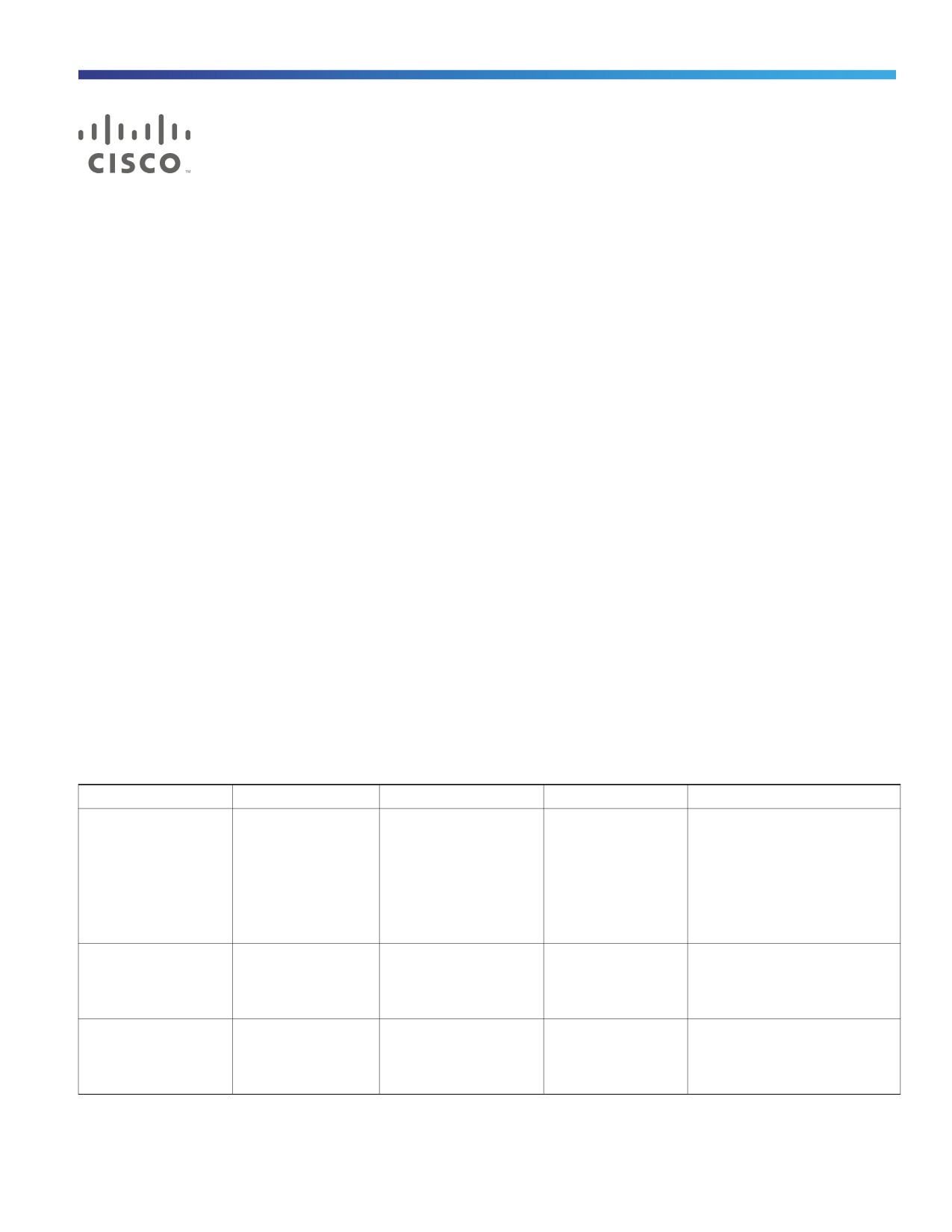
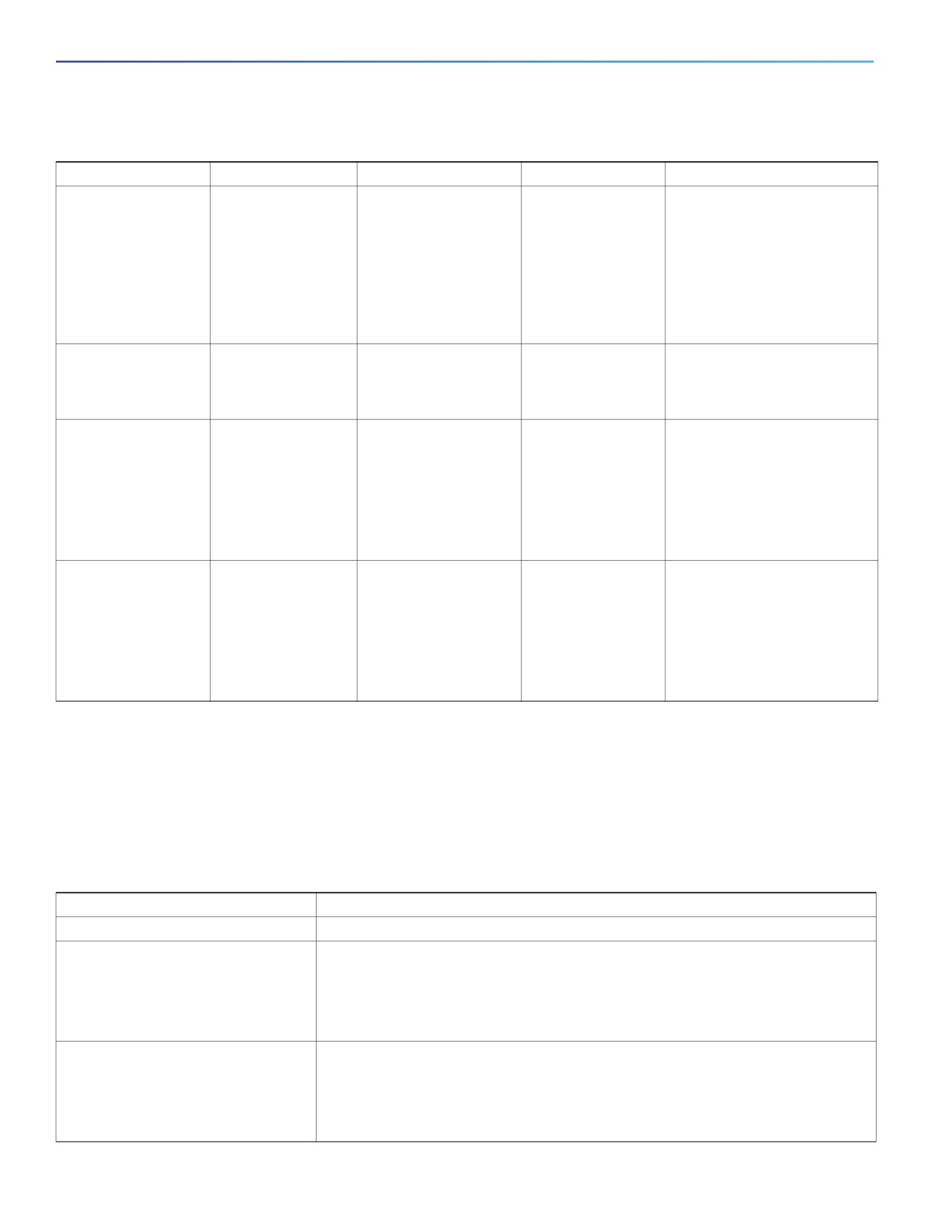
Table 1 on page 9 describes the main command modes, how to access each one, the prompt you see in that mode, and
how to exit the mode. The examples in the table use the hostname Switch.
Table 1
Command Mode Summary
Mode
Access Method
Prompt
Exit Method
About This Mode
Switch>
User EXEC
Begin a session with
Enter logout or
Use this mode to
your switch.
quit.
Change terminal settings.
Perform basic tests.
Display system
information.
Switch#
Privileged EXEC
While in user EXEC
Enter disable to
Use this mode to verify
mode, enter the
exit.
commands that you have
enable command.
entered. Use a password to
protect access to this mode.
Switch(config)#
Global configuration
While in privileged
To exit to privileged
Use this mode to configure
EXEC mode, enter
EXEC mode, enter
parameters that apply to the
the configure
exit or end, or
entire switch.
command.
press Ctrl-Z.
9
Using the Command-Line Interface
Information About Using the Command-Line Interface
Table 1
Command Mode Summary (continued)
Mode
Access Method
Prompt
Exit Method
About This Mode
Switch(config-vlan)
Config-vlan
While in global
To exit to global
Use this mode to configure
#
configuration mode,
configuration
VLAN parameters. When VTP
enter the
mode, enter the
mode is transparent, you can
vlan vlan-id
exit command.
create extended-range VLANs
command.
(VLAN IDs greater than 1005)
To return to
and save configurations in the
privileged EXEC
switch startup configuration
mode, press Ctrl-Z
file.
or enter end.
Switch(vlan)#
VLAN configuration
While in privileged
To exit to privileged
Use this mode to configure
EXEC mode, enter
EXEC mode, enter
VLAN parameters for VLANs 1
the vlan database
exit.
to 1005 in the VLAN database.
command.
Switch(config-if)#
Interface
While in global
To exit to global
Use this mode to configure
configuration
configuration mode,
configuration
parameters for the Ethernet
enter the interface
mode, enter exit.
ports.
command (with a
specific interface).
To return to
privileged EXEC
mode, press Ctrl-Z
or enter end.
Switch(config-line)
Line configuration
While in global
To exit to global
Use this mode to configure
#
configuration mode,
configuration
parameters for the terminal
specify a line with
mode, enter exit.
line.
the line vty or line
console command.
To return to
privileged EXEC
mode, press Ctrl-Z
or enter end.
Help System
You can enter a question mark (?) at the system prompt to display a list of commands available for each command mode.
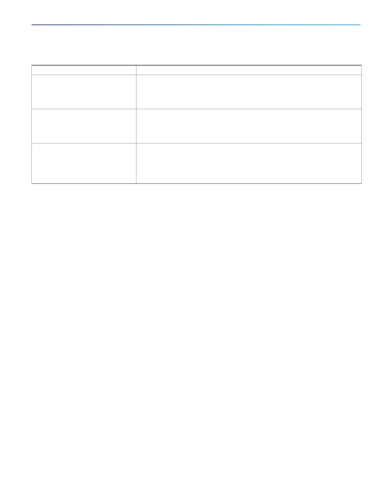
You can also obtain a list of associated keywords and arguments for any command, as shown in Table 2 on page 10.
Table 2
Help Summary
Command
Purpose
help
Obtain a brief description of the help system in any command mode.
abbreviated-command-entry?
Obtain a list of commands that begin with a particular character string.
For example:
Switch# di?
dir disable disconnect
abbreviated-command-entry<Tab>
Complete a partial command name.
For example:
Switch# sh conf<tab>
Switch# show configuration
10
Using the Command-Line Interface
CLI Error Messages
Table 2
Help Summary (continued)
Command
Purpose
?
List all commands available for a particular command mode.
For example:
Switch> ?
command ?
List the associated keywords for a command.
For example:
Switch> show ?
command keyword ?
List the associated arguments for a keyword.
For example:
Switch(config)# cdp holdtime ?
<10-255> Length of time (in sec) that receiver must keep this packet
Understanding Abbreviated Commands
You need to enter only enough characters for the switch to recognize the command as unique.
This example shows how to enter the show configuration privileged EXEC command in an abbreviated form:
Switch# show conf
No and default Forms of Commands
Almost every configuration command also has a no form. In general, use the no form to disable a feature or function or
reverse the action of a command. For example, the no shutdown interface configuration command reverses the
shutdown of an interface. Use the command without the keyword no to reenable a disabled feature or to enable a feature
that is disabled by default.
Configuration commands can also have a default form. The default form of a command returns the command setting to
its default. Most commands are disabled by default, so the default form is the same as the no form. However, some
commands are enabled by default and have variables set to certain default values. In these cases, the default command
enables the command and sets variables to their default values.
CLI Error Messages
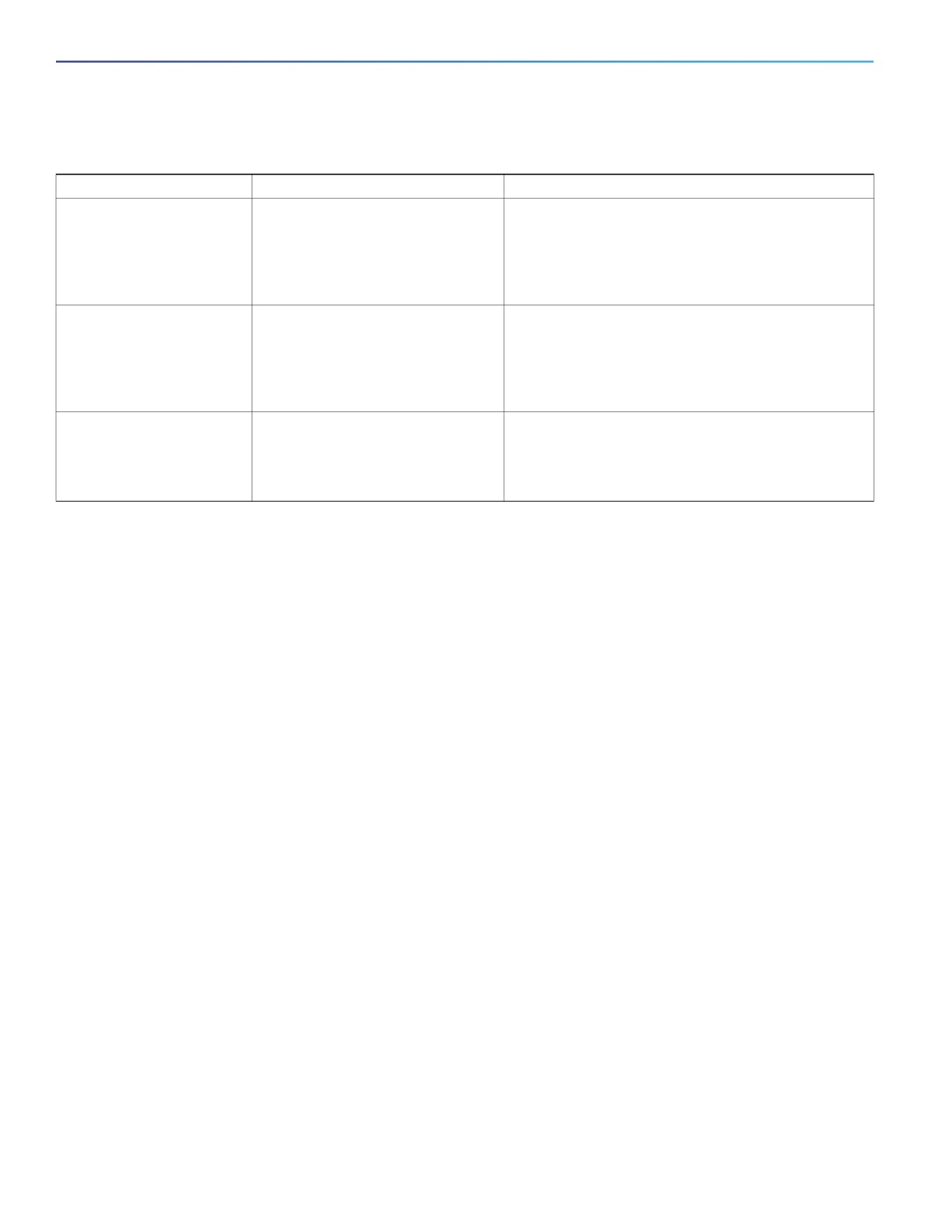
Table 3 on page 12 lists some error messages that you might encounter while using the CLI to configure your switch.
11
Using the Command-Line Interface
How to Use the CLI to Configure Features
Table 3
Common CLI Error Messages
Error Message
Meaning
How to Get Help
% Ambiguous command:
You did not enter enough characters
Reenter the command followed by a question mark (?)
"show con"
for your switch to recognize the
with a space between the command and the question
command.
mark.
The possible keywords that you can enter with the
command appear.
% Incomplete command.
You did not enter all the keywords or
Reenter the command followed by a question mark (?)
values required by this command.
with a space between the command and the question
mark.
The possible keywords that you can enter with the
command appear.
% Invalid input detected
You entered the command
Enter a question mark (?) to display all the commands
at ‘^’ marker.
incorrectly. The caret (^) marks the
that are available in this command mode.
point of the error.
The possible keywords that you can enter with the
command appear.
Configuration Logging
You can log and view changes to the switch configuration. You can use the Configuration Change Logging and
Notification feature to track changes on a per-session and per-user basis. The logger tracks each configuration
command that is applied, the user who entered the command, the time that the command was entered, and the parser
return code for the command. This feature includes a mechanism for asynchronous notification to registered applications
whenever the configuration changes. You can choose to have the notifications sent to the syslog.
Note: Only CLI or HTTP changes are logged.
How to Use the CLI to Configure Features
Configuring the Command History
The software provides a history or record of commands that you have entered. The command history feature is
particularly useful for recalling long or complex commands or entries, including access lists. You can customize this
feature to suit your needs as described in these sections:
Changing the Command History Buffer Size, page 12 (optional)
Recalling Commands, page 13 (optional)
Disabling the Command History Feature, page 13 (optional)
Changing the Command History Buffer Size
By default, the switch records ten command lines in its history buffer. You can alter this number for a current terminal
session or for all sessions on a particular line. These procedures are optional.
Beginning in privileged EXEC mode, enter this command to change the number of command lines that the switch records
during the current terminal session:
Switch# terminal history [size number-of-lines]
12
Using the Command-Line Interface
How to Use the CLI to Configure Features
The range is from 0 to 256.
Beginning in line configuration mode, enter this command to configure the number of command lines the switch records
for all sessions on a particular line:
Switch(config-line)# history [size number-of-lines]
The range is from 0 to 256.
Recalling Commands
To recall commands from the history buffer, perform one of the actions listed in Table 4 on page 13. These actions are
optional.
Table 4
Recalling Commands
Action1
Result
Press Ctrl-P or the up arrow key.
Recall commands in the history buffer, beginning with the most recent command.
Repeat the key sequence to recall successively older commands.
Press Ctrl-N or the down arrow key.
Return to more recent commands in the history buffer after recalling commands
with Ctrl-P or the up arrow key. Repeat the key sequence to recall successively
more recent commands.
show history
While in privileged EXEC mode, list the last several commands that you just
entered. The number of commands that appear is controlled by the setting of the
terminal history global configuration command and the history line configuration
command.
1. The arrow keys function only on ANSI-compatible terminals such as VT100s.
Disabling the Command History Feature
The command history feature is automatically enabled. You can disable it for the current terminal session or for the
command line. These procedures are optional.
To disable the feature during the current terminal session, enter the terminal no history privileged EXEC command.
To disable command history for the line, enter the no history line configuration command.
Using Editing Features
This section describes the editing features that can help you manipulate the command line. It contains these sections:
Enabling and Disabling Editing Features, page 13 (optional)
Editing Commands Through Keystrokes, page 14 (optional)
Editing Command Lines That Wrap, page 15 (optional)
Enabling and Disabling Editing Features
Although enhanced editing mode is automatically enabled, you can disable it, reenable it, or configure a specific line to
have enhanced editing. These procedures are optional.
To globally disable enhanced editing mode, enter this command in line configuration mode:
13

Using the Command-Line Interface
How to Use the CLI to Configure Features
Switch (config-line)# no editing
To reenable the enhanced editing mode for the current terminal session, enter this command in privileged EXEC mode:
Switch# terminal editing
To reconfigure a specific line to have enhanced editing mode, enter this command in line configuration mode:
Switch(config-line)# editing
Editing Commands Through Keystrokes
Table 5 on page 14 shows the keystrokes that you need to edit command lines. These keystrokes are optional.
Table 5
Editing Commands through Keystrokes
Capability
Keystroke1
Purpose
Move around the command line to
Press Ctrl-B, or press the
Move the cursor back one character.
make changes or corrections.
left arrow key.
Press Ctrl-F, or press the
Move the cursor forward one character.
right arrow key.
Press Ctrl-A.
Move the cursor to the beginning of the command line.
Press Ctrl-E.
Move the cursor to the end of the command line.
Press Esc B.
Move the cursor back one word.
Press Esc F.
Move the cursor forward one word.
Press Ctrl-T.
Transpose the character to the left of the cursor with the
character located at the cursor.
Recall commands from the buffer
Press Ctrl-Y.
Recall the most recent entry in the buffer.
and paste them in the command line.
The switch provides a buffer with the
last ten items that you deleted.
Press Esc Y.
Recall the next buffer entry.
The buffer contains only the last 10 items that you have
deleted or cut. If you press Esc Y more than ten times, you
cycle to the first buffer entry.
Delete entries if you make a mistake
Press the Delete or
Erase the character to the left of the cursor.
or change your mind.
Backspace key.
Press Ctrl-D.
Delete the character at the cursor.
Press Ctrl-K.
Delete all characters from the cursor to the end of the
command line.
Press Ctrl-U or Ctrl-X.
Delete all characters from the cursor to the beginning of
the command line.
Press Ctrl-W.
Delete the word to the left of the cursor.
Press Esc D.
Delete from the cursor to the end of the word.
Capitalize or lowercase words or
Press Esc C.
Capitalize at the cursor.
capitalize a set of letters.
Press Esc L.
Change the word at the cursor to lowercase.
Press Esc U.
Capitalize letters from the cursor to the end of the word.
14
Using the Command-Line Interface
How to Use the CLI to Configure Features
Table 5
Editing Commands through Keystrokes (continued)
Capability
Keystroke1
Purpose
Designate a particular keystroke as
Press Ctrl-V or Esc Q.
an executable command, perhaps as
a shortcut.
Scroll down a line or screen on
Press the Return key.
Scroll down one line.
displays that are longer than the
terminal screen can display.
Note: The More prompt is used for
any output that has more lines than
can be displayed on the terminal
screen, including show command
output. You can use the Return and
Space bar keystrokes whenever you
see the More prompt.
Press the Space bar.
Scroll down one screen.
Redisplay the current command line
Press Ctrl-L or Ctrl-R.
Redisplay the current command line.
if the switch suddenly sends a
message to your screen.
1. The arrow keys function only on ANSI-compatible terminals such as VT100s.
Editing Command Lines That Wrap
You can use a wraparound feature for commands that extend beyond a single line on the screen. When the cursor
reaches the right margin, the command line shifts ten spaces to the left. You cannot see the first ten characters of the
line, but you can scroll back and check the syntax at the beginning of the command. The keystroke actions are optional.
To scroll back to the beginning of the command entry, press Ctrl-B or the left arrow key repeatedly. You can also press
Ctrl-A to immediately move to the beginning of the line.
The arrow keys function only on ANSI-compatible terminals such as VT100s.
In this example, the access-list global configuration command entry extends beyond one line. When the cursor first
reaches the end of the line, the line is shifted ten spaces to the left and redisplayed. The dollar sign ($) shows that the
line has been scrolled to the left. Each time the cursor reaches the end of the line, the line is again shifted ten spaces to
the left.
Switch(config)# access-list 101 permit tcp 131.108.2.5 255.255.255.0 131.108.1
Switch(config)# $ 101 permit tcp 131.108.2.5 255.255.255.0 131.108.1.20 255.25
Switch(config)# $t tcp 131.108.2.5 255.255.255.0 131.108.1.20 255.255.255.0 eq
Switch(config)# $108.2.5 255.255.255.0 131.108.1.20 255.255.255.0 eq 45
After you complete the entry, press Ctrl-A to check the complete syntax before pressing the Return key to execute the
command. The dollar sign ($) appears at the end of the line to show that the line has been scrolled to the right:
Switch(config)# access-list 101 permit tcp 131.108.2.5 255.255.255.0 131.108.1$
The software assumes you have a terminal screen that is 80 columns wide. If you have a different width, use the terminal
width privileged EXEC command to set the width of your terminal.
Use line wrapping with the command history feature to recall and modify previous complex command entries. For
information about recalling previous command entries, see Editing Commands Through Keystrokes, page 14.
15
Using the Command-Line Interface
How to Use the CLI to Configure Features
Searching and Filtering Output of show and more Commands
You can search and filter the output for show and more commands. This is useful when you need to sort through large
amounts of output or if you want to exclude output that you do not need to see. Using these commands is optional.
To use this functionality, enter a show or more command followed by the pipe character (|), one of the keywords begin,
include, or exclude, and an expression that you want to search for or filter out:
command | {begin | include | exclude} regular-expression
Expressions are case sensitive. For example, if you enter | exclude output, the lines that contain output are not
displayed, but the lines that contain Output appear.
This example shows how to include in the output display only lines where the expression protocol appears:
Switch# show interfaces | include protocol
Vlan1 is up, line protocol is up
Vlan10 is up, line protocol is down
Accessing the CLI
You can access the CLI through a console connection, through Telnet, or by using the browser.
Accessing the CLI through a Console Connection or through Telnet
To understand the boot process and the options available for assigning IP information, see Performing Switch Setup
Configuration, page 59
If your switch is already configured, you can access the CLI through a local console connection or through a remote Telnet
session, but your switch must first be configured for this type of access. For more information, see Setting the Telnet
Password for a Terminal Line: Example, page 184.
You can use one of these methods to establish a connection with the switch:
Connect the switch console port to a management station or dial-up modem. For information about connecting to
the console port, see the Hardware Installation Guide Hardware Technical Guide.
Use any Telnet TCP/IP or encrypted Secure Shell (SSH) package from a remote management station. The switch
must have network connectivity with the Telnet or SSH client, and the switch must have an enable secret password
configured.
The switch supports up to 16 simultaneous Telnet sessions. Changes made by one Telnet user are reflected in all
other Telnet sessions.
For information about configuring the switch for SSH, see Configuring the SSH Server, page 179. The switch
supports up to five simultaneous secure SSH sessions.
After you connect through the console port, through a Telnet session or through an SSH session, the user EXEC prompt
appears on the management station.
16
Configuring Interfaces
This chapter defines the types of interfaces and describes how to configure them.
Understanding Interface Types, page 17
Using the Switch USB Port, page 26
Using Interface Configuration Mode, page 27
Configuring Ethernet Interfaces, page 31
Configuring Layer 3 Interfaces, page 42
Configuring the System MTU, page 43
Monitoring and Maintaining the Interfaces, page 45
Understanding Interface Types
This section describes the different types of interfaces supported by the switch with references to chapters that contain
more detailed information about configuring these interface types. The rest of the chapter describes configuration
procedures for physical interface characteristics.
UNI, NNI, and ENI Port Types, page 17
Port-Based VLANs, page 18
Switch Ports, page 19
Routed Ports, page 20
Switch Virtual Interfaces, page 20
EtherChannel Port Groups, page 20
Power over Ethernet Ports, page 21
Connecting Interfaces, page 25
UNI, NNI, and ENI Port Types
The switch supports user-network interfaces (UNIs), network node interfaces (NNIs), and enhanced network interfaces
(ENIs). UNIs are typically connected to a host, such as a PC or a Cisco IP phone. NNIs are typically connected to a router
or to another switch. ENIs have the same functionality as UNIs, but can be configured to support protocol control packets
for Cisco Discovery Protocol (CDP), Spanning-Tree Protocol (STP), Link Layer Discovery Protocol (LLDP), and
EtherChannel Link Aggregation Control Protocol (LACP) or Port Aggregation Protocol (PAgP).
By default, all ports are enabled as NNI.
All ports on the switch can be configured as UNIs or ENIs.
17
Configuring Interfaces
Understanding Interface Types
The default state for a UNI or ENI is administratively down to prevent unauthorized users from gaining access to other
ports as you configure the switch. Traffic is not switched between these ports, and all arriving traffic at UNIs or ENIs must
leave on NNIs to prevent a user from gaining access to another user’s private network. If it is appropriate for two or more
UNIs or ENIs to exchange traffic within the switch, the UNIs and ENIs can be assigned to a community VLAN. See
Chapter 20, “Configuring VLANs,” for instructions on how to configure community VLANs.
Note: Even though the default state for a UNI or ENI is shutdown, entering the default interface interface-id command
changes the port to the enabled state.
The default status for an NNI is administratively up to allow a service provider remote access to the switch during initial
configuration.
A port can be reconfigured from UNI to NNI or ENI and the reverse. When a port is reconfigured as another interface type,
it inherits all the characteristics of that interface type. When you reconfigure a UNI or ENI to be an NNI, you must enable
the port before it becomes active.
Changing the port type from UNI to ENI does not affect the administrative state of the port. If the UNI status is shut down,
it remains shut down when reconfigured as an ENI; if the port is in a no shutdown state, it remains in the no shutdown
state. At any time, all ports on the switch are either UNI, NNI, or ENI.
Port-Based VLANs
A VLAN is a switched network that is logically segmented by function, team, or application, without regard to the physical
location of the users. Packets received on a port are forwarded only to ports that belong to the same VLAN as the
receiving port. Network devices in different VLANs cannot communicate with one another without a Layer 3 device to
route traffic between the VLANs.
VLAN partitions provide hard firewalls for traffic in the VLAN, and each VLAN has its own MAC address table. A VLAN
comes into existence when a local port is associated with the VLAN ID or when a user creates te VLAN ID.
To isolate VLANs of different customers in a service-provider network, the switch uses UNI-ENI VLANs. UNI-ENI VLANs
isolate user network interfaces (UNIs) or enhanced network interfaces (ENIs) on the switch from UNIs or ENIs that belong
to other customer VLANs. There are two types of UNI-ENI VLANs:
UNI-ENI isolated VLAN—This is the default VLAN state for all VLANs created on the switch. Local switching does not
occur among UNIs or ENIs on the switch that belong to the same UNI-ENI isolated VLAN.
UNI-ENI community VLAN—Local switching is allowed among UNIs and ENIs on the switch that belong to the same
UNI community VLAN. If UNIs or ENIs belong to the same customer, and you want to switch packets between the
ports, you can configure the common VLAN as a UNI-ENI community VLAN.
Note: Local switching takes place between ENIs and UNIs in the same community VLAN. Because you can enable
spanning tree on ENIs, but not on UNIs, you should use caution when configuring ENIs and UNIs in the same
community VLAN. UNIs are always in the forwarding state.
To configure VLANs, use the vlan vlan-id global configuration command to enter VLAN configuration mode. The VLAN
configurations for VLAN IDs 1 to 1005 are saved in the VLAN database. Extended-range VLANs (VLAN IDs 1006 to 4094)
are not added to the VLAN database. VLAN configuration is saved in the switch running configuration, and you can save
it in the switch startup configuration file by entering the copy running-config startup-config privileged EXEC command.
Add ports to a VLAN by using the switchport interface configuration commands:
Identify the interface.
For a trunk port, set trunk characteristics, and if desired, define the VLANs to which it can belong.
For an access port, set and define the VLAN to which it belongs.
For a tunnel port, set and define the VLAN ID for the customer-specific VLAN tag.
18
Configuring Interfaces
Understanding Interface Types
Switch Ports
Switch ports are Layer 2 only interfaces associated with a physical port. Switch ports belong to one or more VLANs. A
switch port can be an access port, a trunk port, a private-VLAN port, or a tunnel port. You can configure a port as an
access port or trunk port. You configure a private VLAN port as a host or promiscuous port that belongs to a private-VLAN
primary or secondary VLAN. (Only NNIs can be configured as promiscuous ports.) You must manually configure tunnel
ports as part of an asymmetric link connected to an IEEE 802.1Q trunk port. Switch ports are used for managing the
physical interface and associated Layer 2 protocols and do not handle routing or bridging.
Configure switch ports by using the switchport interface configuration commands. Use the switchport command with
no keywords to put an interface that is in Layer 3 mode into Layer 2 mode.
Note: When you put an interface that is in Layer 3 mode into Layer 2 mode, the previous configuration information related
to the affected interface might be lost, and the interface is returned to its default configuration.
Access Ports
An access port belongs to and carries the traffic of only one VLAN. Traffic is received and sent in native formats with no
VLAN tagging. Traffic arriving on an access port is assumed to belong to the VLAN assigned to the port. If an access port
receives an 802.1Q tagged packet, the packet is dropped, and the source address is not learned. 802.1x can also be
used for VLAN assignment.
Two types of access ports are supported:
Static access ports are manually assigned to a VLAN.
VLAN membership of dynamic access ports is learned through incoming packets. By default, a dynamic access port
is a member of no VLAN, and forwarding to and from the port is enabled only when the VLAN membership of the
port is discovered. UNIs begin forwarding packets as soon as they are enabled. Dynamic access ports on the switch
are assigned to a VLAN by a VLAN Membership Policy Server (VMPS). Dynamic access ports for VMPS are only
supported on UNIs and ENIs.
Trunk Ports
An 802.1Q trunk port carries the traffic of multiple VLANs and by default is a member of all VLANs in the VLAN database.
A trunk port supports simultaneous tagged and untagged traffic. An 802.1Q trunk port is assigned a default Port VLAN
ID (PVID), and all untagged traffic travels on the port default PVID. All untagged traffic and tagged traffic with a NULL
VLAN ID are assumed to belong to the port default PVID. A packet with a VLAN ID equal to the outgoing port default PVID
is sent untagged. All other traffic is sent with a VLAN tag.
Although by default a trunk port is a member of multiple VLANs, you can limit VLAN membership by configuring an
allowed list of VLANs for each trunk port. The list of allowed VLANs does not affect any other port but the associated
trunk port. By default, all possible VLANs (VLAN ID 1 to 4094) are in the allowed list. A trunk port can become a member
of a VLAN only if the VLAN is in the enabled state.
For more information about trunk ports, see Configuring VLANs, page 289
Tunnel Ports
Tunnel ports are used in 802.1Q tunneling to segregate the traffic of customers in a service-provider network from other
customers who are using the same VLAN number. You configure an asymmetric link from a tunnel port on a
service-provider edge switch to an 802.1Q trunk port on the customer switch. Packets entering the tunnel port on the
edge switch, already IEEE 802.1Q-tagged with the customer VLANs, are encapsulated with another layer of an 802.1Q
tag (called the metro tag), containing a VLAN ID unique in the service-provider network, for each customer. The
double-tagged packets go through the service-provider network keeping the original customer VLANs separate from
those of other customers. At the outbound interface, also a tunnel port, the metro tag is removed, and the original VLAN
numbers from the customer network are retrieved.
19
Configuring Interfaces
Understanding Interface Types
Note: IEEE 802.1Q tunneling is only supported when the switch is running the IP Services license.
Tunnel ports cannot be trunk ports or access ports and must belong to a VLAN unique to each customer.
Routed Ports
A routed port is a physical port that acts like a port on a router; it does not have to be connected to a router. A routed
port is not associated with a particular VLAN, as is an access port. A routed port behaves like a regular router interface,
except that it does not support VLAN subinterfaces. Routed ports can be configured with a Layer 3 routing protocol. A
routed port is a Layer 3 interface only and does not support Layer 2 protocols, such as STP.
Configure routed ports by putting the interface into Layer 3 mode with the no switchport interface configuration
command. Then assign an IP address to the port, enable routing, and assign routing protocol characteristics by using the
ip routing and router protocol global configuration commands.
Note: Entering a no switchport interface configuration command shuts down the interface and then re-enables it, which
might generate messages on the device to which the interface is connected. When you put an interface that is in Layer
2 mode into Layer 3 mode, the previous configuration information related to the affected interface might be lost.
The number of routed ports that you can configure is not limited by software. However, the interrelationship between this
number and the number of other features being configured might impact CPU performance because of hardware
limitations. See Configuring Layer 3 Interfaces, page 42 for information about what happens when hardware resource
limitations are reached.
Note: For full Layer 3 routing, you must have the IP services image installed on the switch
Switch Virtual Interfaces
A switch virtual interface (SVI) represents a VLAN of switch ports as one interface to the routing or bridging function in
the system. Only one SVI can be associated with a VLAN, but you need to configure an SVI for a VLAN only when you
wish to route between VLANs or to provide IP host connectivity to the switch. By default, an SVI is created for the default
VLAN (VLAN 1) to permit remote switch administration. Additional SVIs must be explicitly configured.
Note: You cannot delete interface VLAN 1.
SVIs provide IP host connectivity only to the system; in Layer 3 mode, you can configure routing across SVIs.
Although the switch supports a total of 1005 VLANs (and SVIs), the interrelationship between the number of SVIs and
routed ports and the number of other features being configured might impact CPU performance because of hardware
limitations. See Configuring Layer 3 Interfaces, page 42 for information about what happens when hardware resource
limitations are reached.
SVIs are created the first time that you enter the vlan interface configuration command for a VLAN interface. The VLAN
corresponds to the VLAN tag associated with data frames on an IEEE 802.1Q encapsulated trunk or the VLAN ID
configured for an access port. Configure a VLAN interface for each VLAN for which you want to route traffic, and assign
it an IP address. For more information, see Manually Assigning IP Information to SVIs, page 71.
Note: When you create an SVI, it does not become active until it is associated with a physical port.
SVIs support routing protocols.
Note: Routed ports (or SVIs) are supported only when the IP services image is installed on the switch.
EtherChannel Port Groups
EtherChannel port groups treat multiple switch ports as one switch port. These port groups act as a single logical port
for high-bandwidth connections between switches or between switches and servers. An EtherChannel balances the
traffic load across the links in the channel. If a link within the EtherChannel fails, traffic previously carried over the failed
link changes to the remaining links. You can group multiple trunk ports into one logical trunk port, group multiple access
20
Configuring Interfaces
Understanding Interface Types
ports into one logical access port, group multiple tunnel ports into one logical tunnel port, or group multiple routed ports
into one logical routed port. Most protocols operate over either single ports or aggregated switch ports and do not
recognize the physical ports within the port group. Exceptions are the Cisco Discovery Protocol (CDP), Link Aggregation
Control Protocol (LACP), and the Port Aggregation Protocol (PAgP), which operate only on physical NNI or ENI ports.
When you configure an EtherChannel, you create a port-channel logical interface and assign an interface to the
EtherChannel. For Layer 3 interfaces, you manually create the logical interface by using the interface port-channel
global configuration command. Then you manually assign an interface to the EtherChannel by using the channel-group
interface configuration command. For Layer 2 interfaces, use the channel-group interface configuration command to
dynamically create the port-channel logical interface. This command binds the physical and logical ports together. For
more information, see Configuring EtherChannels, page 1069
Power over Ethernet Ports
PoE-capable switch ports automatically supply power to these connected devices (if the switch senses that there is no
power on the circuit):
Cisco pre-standard powered devices (such as Cisco IP Phones and Cisco Aironet access points)
802.3af/802.3at-compliant powered devices
A powered device can receive redundant power when it is connected only to a PoE switch port and to an AC power
source.
After the switch detects a powered device, it determines the device power requirements and then grants or denies power
to the device. The switch can also sense the real-time power consumption of the device by monitoring and policing the
power usage.
This section has this PoE information:
Supported Protocols and Standards, page 21
Powered-Device Detection and Initial Power Allocation, page 22
Power Management Modes, page 22
Supported Protocols and Standards
The switch uses these protocols and standards to support PoE:
CDP with power consumption—The powered device notifies the switch of the amount of power it is consuming. The
switch does not reply to the power-consumption messages. The switch can only supply power to or remove power
from the PoE port.
Cisco intelligent power management—The powered device and the switch negotiate through power-negotiation CDP
messages for an agreed power-consumption level. The negotiation allows a high-power Cisco powered device,
which consumes more than 7 W, to operate at its highest power mode. The powered device first boots up in
low-power mode, consumes less than 7 W, and negotiates to obtain enough power to operate in high-power mode.
The device changes to high-power mode only when it receives confirmation from the switch.
High-power devices can operate in low-power mode on switches that do not support power-negotiation CDP.
Cisco intelligent power management is backward-compatible with CDP with power consumption; the switch
responds according to the CDP message that it receives. CDP is not supported on third-party powered devices;
therefore, the switch uses the IEEE classification to determine the power usage of the device.
IEEE 802.3af/802.3at—The major features of this standard are powered-device discovery, power administration,
disconnect detection, and optional powered-device power classification. For more information, see the standard.
21

Configuring Interfaces
Understanding Interface Types
Powered-Device Detection and Initial Power Allocation
The switch detects a Cisco pre-standard or an IEEE-compliant powered device when the PoE-capable port is in the
no-shutdown state, PoE is enabled (the default), and the connected device is not being powered by an AC adaptor.
After device detection, the switch determines the device power requirements based on its type:
A Cisco pre-standard powered device does not provide its power requirement when the switch detects it, so the
switch allocates 15.4 W as the initial allocation for power budgeting.
The initial power allocation is the maximum amount of power that a powered device requires. The switch initially
allocates this amount of power when it detects and powers the powered device. As the switch receives CDP
messages from the powered device and as the powered device negotiates power levels with the switch through CDP
power-negotiation messages, the initial power allocation might be adjusted.
The switch classifies the detected IEEE device within a power consumption class. Based on the available power in
the power budget, the switch determines if a port can be powered. Table 1 lists these levels.
Class
Maximum Power Level Required from the Switch
0 (class status unknown)
15.4 W
1
4 W
2
7 W
3
15.4 W
4 (POE+)
30 W (requires LLDP)
Note: Prior to release 15.2(6)E1, if a rack mounted, IE4010 or IE5000 series switch, was powered by 2
PWR-RGD-AC-DC-250 power supplies, the correct total PoE budget (385W) as indicated in the Data Sheet, would not
be displayed. If the proper total power budget isn’t displayed on your switch, upgrade to release 15.2(6)E1 or later.
The switch monitors and tracks requests for power and grants power only when it is available. The switch tracks its power
budget (the amount of power available on the switch for PoE). The switch performs power-accounting calculations when
a port is granted or denied power to keep the power budget up to date.
After power is applied to the port, the switch uses CDP to determine the actual power consumption requirement of the
connected Cisco powered devices, and the switch adjusts the power budget accordingly. This does not apply to
third-party PoE devices. The switch processes a request and either grants or denies power. If the request is granted, the
switch updates the power budget. If the request is denied, the switch ensures that power to the port is turned off,
generates a syslog message, and updates the LEDs. Powered devices can also negotiate with the switch for more power.
If the switch detects a fault caused by an undervoltage, overvoltage, overtemperature, oscillator-fault, or short-circuit
condition, it turns off power to the port, generates a syslog message, and updates the power budget and LEDs.
Note: IE switches may show occasional PoE controller error messages on the console, for example:
%ILPOWER-3-CONTROLLER_ERR: Controller error, Controller number 0: accessing failed
This can occur when there are no powered devices connected and all ports continue to function normally. There are no
workarounds. These messages can be ignored.
If these or any other errors seen cause performance issues, contact Cisco support.
Power Management Modes
To limit the overall PoE budget of DIN rail switches such as the IE-4000, use the global configuration command power
inline wattage max <4-125>.
22
Configuring Interfaces
Understanding Interface Types
Note - This command does not apply to rack-mount switches with integrated power supplies, such as the IE-4010 and
IE-5000.
The switch supports these PoE modes:
auto—The switch automatically detects if the connected device requires power. If the switch discovers a powered
device connected to the port and if the switch has enough power, it grants power, updates the power budget, turns
on power to the port on a first-come, first-served basis, and updates the LEDs. For LED information, see the
hardware installation guide.
If the switch has enough power for all the powered devices, they all come up. If enough power is available for all
powered devices connected to the switch, power is turned on to all devices. If there is not enough available PoE, or
if a device is disconnected and reconnected while other devices are waiting for power, it cannot be determined
which devices are granted or are denied power.
If granting power would exceed the system power budget, the switch denies power, ensures that power to the port
is turned off, generates a syslog message, and updates the LEDs. After power has been denied, the switch
periodically rechecks the power budget and continues to attempt to grant the request for power.
If a device being powered by the switch is then connected to wall power, the switch might continue to power the
device. The switch might continue to report that it is still powering the device whether the device is being powered
by the switch or receiving power from an AC power source.
If a powered device is removed, the switch automatically detects the disconnect and removes power from the port.
You can connect a nonpowered device without damaging it.
You can specify the maximum wattage that is allowed on the port. If the IEEE class maximum wattage of the powered
device is greater than the configured maximum value, the switch does not provide power to the port. If the switch
powers a powered device, but the powered device later requests through CDP messages more than the configured
maximum value, the switch removes power to the port. The power that was allocated to the powered device is
reclaimed into the global power budget. If you do not specify a wattage, the switch delivers the maximum value. Use
the auto setting on any PoE port. The auto mode is the default setting.
static—The switch pre-allocates power to the port (even when no powered device is connected) and guarantees
that power will be available for the port. The switch allocates the port configured maximum wattage, and the amount
is never adjusted through the IEEE class or by CDP messages from the powered device. Because power is
pre-allocated, any powered device that uses less than or equal to the maximum wattage is guaranteed to be
powered when it is connected to the static port. The port no longer participates in the first-come, first-served model.
However, if the powered-device IEEE class is greater than the maximum wattage, the switch does not supply power
to it. If the switch learns through CDP messages that the powered device needs more than the maximum wattage,
the powered device is shutdown.
If you do not specify a wattage, the switch pre-allocates the maximum value. The switch powers the port only if it
discovers a powered device. Use the static setting on a high-priority interface.
never—The switch disables powered-device detection and never powers the PoE port even if an unpowered device
is connected. Use this mode only when you want to make sure power is never applied to a PoE-capable port, making
the port a data-only port.
For information on configuring a PoE port, see Configuring a Power Management Mode on a PoE Port, page 36.
Power Monitoring and Power Policing
When policing of the real-time power consumption is enabled, the switch takes action when a powered device consumes
more power than the maximum amount allocated, also referred to as the cutoff-power value.
23
Configuring Interfaces
Understanding Interface Types
When PoE is enabled, the switch senses the real-time power consumption of the powered device. The switch monitors
the real-time power consumption of the connected powered device; this is called power monitoring or power sensing.
The switch also polices the power usage with the power policing feature.
Power monitoring is backward-compatible with Cisco intelligent power management and CDP-based power
consumption. It works with these features to ensure that the PoE port can supply power to the powered device. For more
information about these PoE features, see Supported Protocols and Standards, page 21.
The switch senses the real-time power consumption of the connected device as follows:
1. The switch monitors the real-time power consumption on individual ports.
2. The switch records the power consumption, including peak power usage. The switch reports the information through
the CISCO-POWER-ETHERNET-EXT-MIB.
3. If power policing is enabled, the switch polices power usage by comparing the real-time power consumption to the
maximum power allocated to the device. For more information about the maximum power consumption, also
referred to as the cutoff power, on a PoE port, see Maximum Power Allocation (Cutoff Power) on a PoE Port, page 24.
If the device uses more than the maximum power allocation on the port, the switch can either turn off power to the
port, or the switch can generate a syslog message and update the LEDs (the port LED is now blinking amber) while
still providing power to the device based on the switch configuration. By default, power-usage policing is disabled
on all PoE ports.
If error recovery from the PoE error-disabled state is enabled, the switch automatically takes the PoE port out of the
error-disabled state after the specified amount of time.
If error recovery is disabled, you can manually re-enable the PoE port by using the shutdown and no shutdown
interface configuration commands.
4. If policing is disabled, no action occurs when the powered device consumes more than the maximum power
allocation on the PoE port, which could adversely affect the switch.
Maximum Power Allocation (Cutoff Power) on a PoE Port
When power policing is enabled, the switch determines one of the these values as the cutoff power on the PoE port in
this order:
1. Manually when you set the user-defined power level that the switch budgets for the port by using the power inline
consumption default wattage global or interface configuration command
2. Manually when you set the user-defined power level that limits the power allowed on the port by using the power
inline auto max max-wattage or the power inline static max max-wattage interface configuration command
3. Automatically when the switch sets the power usage of the device by using CDP power negotiation or by the IEEE
classification
4. Automatically when the switch sets the power usage to be the default value of 15400 mW
Use the first or second method in the previous list to manually configure the cutoff-power value by entering the power
inline consumption default wattage or the power inline [auto | static max] max-wattage command. If you are not
manually configuring the cutoff-power value, the switch automatically determines the value by using CDP power
negotiation or the device IEEE classification, which is the third method in the previous list. If the switch cannot determine
the value by using one of these methods, it uses the default value of 15400 mW (the fourth method in the previous list).
Power Consumption Values
You can configure the initial power allocation and the maximum power allocation on a port. However, these values are
only the configured values that determine when the switch should turn on or turn off power on the PoE port. The maximum
power allocation is not the same as the actual power consumption of the powered device. The actual cutoff power value
that the switch uses for power policing is not equal to the configured power value.
24
Configuring Interfaces
Understanding Interface Types
When power policing is enabled, the switch polices the power usage at the switch port, which is greater than the power
consumption of the device. When you are manually set the maximum power allocation, you must consider the power loss
over the cable from the switch port to the powered device. The cutoff power is the sum of the rated power consumption
of the powered device and the worst-case power loss over the cable.
The actual amount of power consumed by a powered device on a PoE port is the cutoff-power value plus a calibration
factor of 500 mW (0.5 W). The actual cutoff value is approximate and varies from the configured value by a percentage
of the configured value. For example, if the configured cutoff power is 12 W, the actual cutoff-value is 11.4 W, which is
5% less than the configured value.
We recommend that you enable power policing when PoE is enabled on your switch. For example, if policing is disabled
and you set the cutoff-power value by using the power inline auto max 6300 interface configuration command, the
configured maximum power allocation on the PoE port is 6.3 W (6300 mW). The switch provides power to the connected
devices on the port if the device needs up to 6.3 W. If the CDP-power negotiated value or the IEEE classification value
exceeds the configured cutoff value, the switch does not provide power to the connected device. After the switch turns
on power on the PoE port, the switch does not police the real-time power consumption of the device, and the device
can consume more power than the maximum allocate d amount, which could adversely affect the switch and the devices
connected to the other PoE ports.
Because the switch supports internal power supplies and the Cisco Redundant Power System 2300 (also referred to as
the RPS 2300), the total amount of power available for the powered devices varies depending on the power supply
configuration.
The switch supports dual power supplies. If a power supply is removed or fails and the switch does not have enough
power for the powered devices, the switch first denies power to low-priority ports in descending order of port numbers,
and then to high priority ports in descending numbers. The total available PoE power is 65 watts per power supply.
If a power supply is removed and replaced by a new power supply with less power and the switch does not have
enough power for the powered devices, the switch denies power to the PoE ports in auto mode in descending order
of the port numbers. If the switch still does not have enough power, the switch then denies power to the PoE ports
in static mode in descending order of the port numbers.
If the new power supply supports more power than the previous one and the switch now has more power available,
the switch grants power to the PoE ports in static mode in ascending order of the port numbers. If it still has power
available, the switch then grants power to the PoE ports in auto mode in ascending order of the port numbers.
Dual-Purpose Ports on IE 4000
Each dual-purpose port is considered a single interface with dual front ends (an RJ-45 connector and an SFP module
connector). The dual front ends are not redundant interfaces; the switch activates only one connector of the pair.
By default, dual-purpose ports are user-network interfaces (UNIs) and SFP-only module ports are network node
interfaces (NNIs). TBy default, the switch dynamically selects the dual-purpose port media type that first links up.
However, you can use the media-type interface configuration command to manually select the RJ-45 connector or the
SFP module connector.
Each dual-purpose port has two LEDs: one shows the status of the SFP module port, and one shows the status of the
RJ-45 port. The port LED is on for whichever connector is active. For more information about the LEDs, see the
hardware installation guide.
Connecting Interfaces
Devices within a single VLAN can communicate directly through any switch. Ports in different VLANs cannot exchange
data without going through a routing device. With a standard Layer 2 switch, ports in different VLANs have to exchange
information through a router.
25
Configuring Interfaces
Using the Switch USB Port
By default, the switch provides VLAN isolation between UNIs or ENIs. UNIs and ENIs cannot exchange traffic unless they
are changed to NNIs or assigned to a UNI-ENI community VLAN.
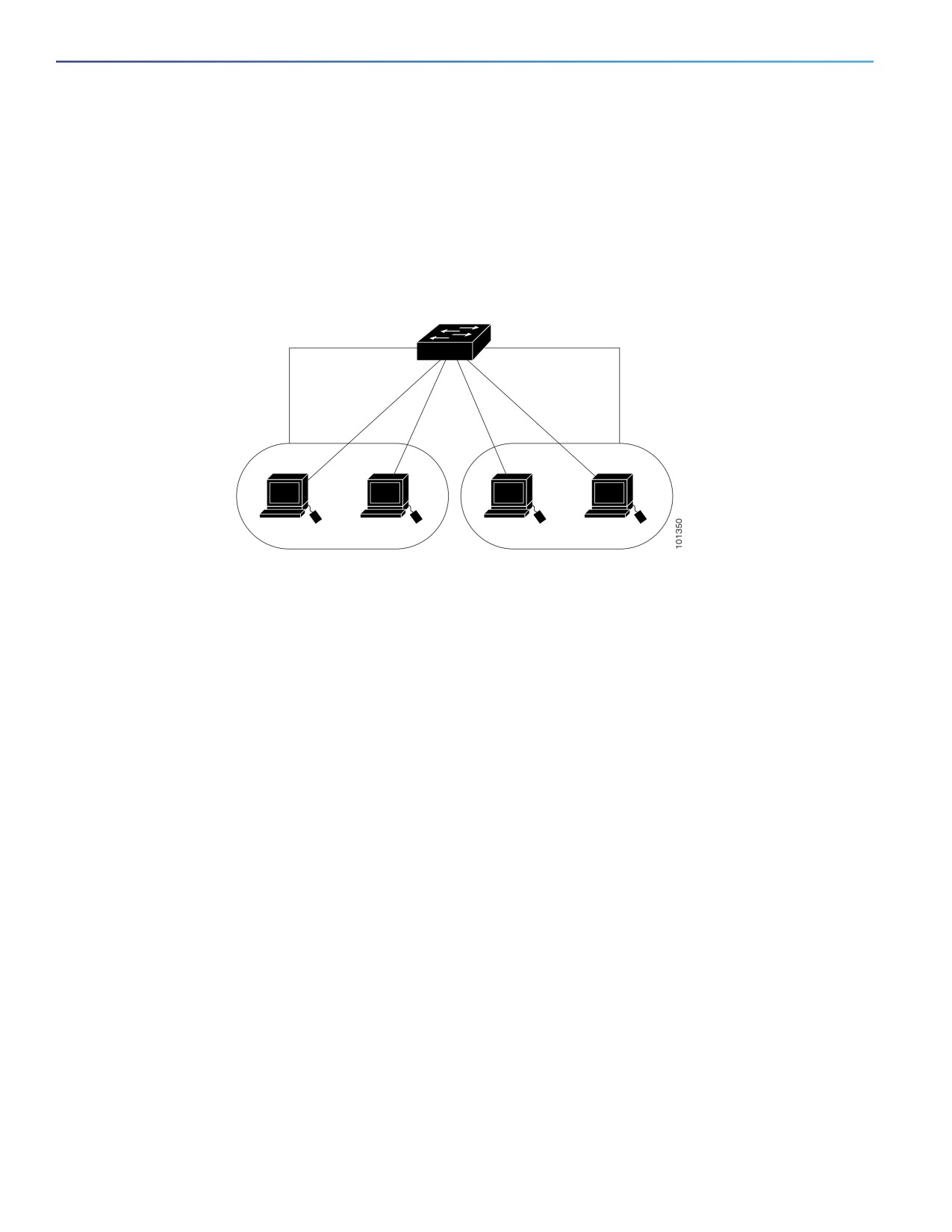
By using the switch with routing enabled, when you configure both VLAN 20 and VLAN 30 with an SVI to which an IP
address is assigned, packets can be sent from Host A to Host B directly through the switch with no need for an external
router (Figure 1 on page 26).
Figure 1
Connecting VLANs with the Switch
Layer 3 switch
with routing enabled
172.20.128.1
SVI 1
SVI 2
172.20.129.1
Host A
Host B
VLAN 20
VLAN 30
When the IP services image is running on the switch, routing can be enabled on the switch. Whenever possible, to
maintain high performance, forwarding is done by the switch hardware. However, only IP Version 4 packets with Ethernet
II encapsulation can be routed in hardware. The routing function can be enabled on all SVIs and routed ports. The switch
routes only IP traffic. When IP routing protocol parameters and address configuration are added to an SVI or routed port,
any IP traffic received from these ports is routed.
Using the Switch USB Port
Note: Windows PCs require a driver for the USB port. See the hardware installation guide for driver installation
instructions.
Use the supplied USB Type A-to-USB mini-Type B cable to connect a PC or other device to the switch. The connected
device must include a terminal emulation application. When the switch detects a valid USB connection to a powered-on
device that supports host functionality (such as a PC), input from the RJ-45 console is immediately disabled, and input
from the USB console is enabled. Removing the USB connection immediately reenables input from the RJ-45 console
connection. A LED on the switch shows which console connection is in use.
Console Port Change Logs
At software startup, a log shows whether the USB or the RJ-45 console port is active. The switch first displays the RJ-45
media type.
In the sample output, the switch has a connected USB console cable. Because the bootloader did not change to the USB
console, the first log from the switch shows the RJ-45 console. A short time later, the console changes and the USB
console log appears.
switch
*Mar
1 00:01:00.171: %USB_CONSOLE-6-MEDIA_RJ45: Console media-type is RJ45.
*Mar
1 00:01:00.431: %USB_CONSOLE-6-MEDIA_USB: Console media-type is USB.
When the USB cable is removed or the PC de-activates the USB connection, the hardware automatically changes to the
RJ-45 console interface:
26

Configuring Interfaces
Using Interface Configuration Mode
switch
Mar
1 00:20:48.635: %USB_CONSOLE-6-MEDIA_RJ45: Console media-type is RJ45.
You can configure the console type to always be RJ-45, and you can configure an inactivity timeout for the USB
connector.
Configuring the Console Media Type
Beginning in privileged EXEC mode, follow these steps to select the RJ-45 console media type. If you configure the
RJ-45 console, USB console operation is disabled, and input always remains with the RJ-45 console.
Command
Purpose
1.
configure terminal
Enter global configuration mode.
2.
line console 0
Configure the console. Enter line configuration mode.
3.
media-type rj45
Configure the console media type to always be RJ-45. If you do not
enter this command and both types are connected, the default is
USB.
4.
end
Return to privileged EXEC mode.
5.
show running-configuration
Verify your settings.
6.
copy running-config startup-config
(Optional) Save your entries in the configuration file.
This example disables the USB console media type and enables the RJ-45 console media type.
Switch# configure terminal
Switch(config)# line console 0
Switch(config-line)# media-type rj45
A log shows that this termination has occurred. This example shows that the console on switch reverted to RJ-45.
*Mar
1 00:25:36.860: %USB_CONSOLE-6-CONFIG_DISABLE: Console media-type USB disabled by system
configuration, media-type reverted to RJ45.
A log entry shows when a console cable is attached. If a USB console cable is connected to the switch, it is prevented
from providing input.
*Mar
1 00:34:27.498: %USB_CONSOLE-6-CONFIG_DISALLOW: Console media-type USB is disallowed by system
configuration, media-type remains RJ45.
This example reverses the previous configuration and immediately activates the USB console that is connected.
Switch# configure terminal
Switch(config)# line console 0
Switch(config-line)# no media-type rj45
Using Interface Configuration Mode
The switch supports these interface types:
Physical ports—switch ports, routed ports, UNIs, NNIs, and ENIs
VLANs—switch virtual interfaces
Port-channels—EtherChannel interfaces
27
Configuring Interfaces
Using Interface Configuration Mode
You can also configure a range of interfaces (see Configuring a Range of Interfaces, page 29).
To configure a physical interface (port), specify the interface type, the module number, and the switch port number, and
enter interface configuration mode.
Type—10/100/1000 Mbps Ethernet ports, Gigabit Ethernet (gigabitethernet or gi), TenGigabitEthernet
(tengigethernet or te) for or small form-factor pluggable (SFP) module Gigabit Ethernet interfaces.
Module number—The module or slot number on the switch.
Port number—The interface number on the switch. The port numbers always begin at 1, starting with the leftmost
port when facing the front of the switch, for example, gigabitethernet 1/1. If there is more than one interface type
(for example, 10/100 ports and SFP module ports), the port numbers restart with the second interface type:
gigabitethernet 1/1.
You can identify physical interfaces by physically checking the interface location on the switch. You can also use the show
privileged EXEC commands to display information about a specific interface or all the interfaces on the switch. The
remainder of this chapter primarily provides physical interface configuration procedures.
Procedures for Configuring Interfaces
These general instructions apply to all interface configuration processes.
1. Enter the configure terminal command at the privileged EXEC prompt:
Switch# configure terminal
Enter configuration commands, one per line. End with CNTL/Z.
Switch(config)#
2. Enter the interface global configuration command. Identify the interface type and the number of the connector. In
this example, Fast Ethernet port 1 is selected:
Switch(config)# interface fastethernet0/1
Switch(config-if)#
Note: You do not need to add a space between the interface type and interface number. For example, in the
preceding line, you can specify either fastethernet 0/1, fastethernet0/1, fa 0/1, or fa0/1.
3. If you are configuring a UNI or ENI, enter the no shutdown interface configuration command to enable the interface:
Switch(config-if)# no shutdown
4. Follow each interface command with the interface configuration commands that the interface requires. The
commands that you enter define the protocols and applications that will run on the interface. The commands are
collected and applied to the interface when you enter another interface command or enter end to return to privileged
EXEC mode.
You can also configure a range of interfaces by using the interface range or interface range macro global configuration
commands. Interfaces configured in a range must be the same type and must be configured with the same feature
options.
5. After you configure an interface, verify its status by using the show privileged EXEC commands listed in the
Monitoring and Maintaining the Interfaces, page 45.
Enter the show interfaces privileged EXEC command to see a list of all interfaces on or configured for the switch. A
report is provided for each interface that the device supports or for the specified interface.
28

Configuring Interfaces
Using Interface Configuration Mode
Configuring a Range of Interfaces
You can use the interface range global configuration command to configure multiple interfaces with the same
configuration parameters. When you enter the interface range configuration mode, all command parameters that you
enter are attributed to all interfaces within that range until you exit this mode.
Beginning in privileged EXEC mode, follow these steps to configure a range of interfaces with the same parameters:
Command
Purpose
1.
configure terminal
Enter global configuration mode.
2.
interface range {port-range}
Specify the range of interfaces (VLANs or physical ports) to be
configured, and enter interface range configuration mode.
You can use the interface range command to configure up to five
port ranges or a previously defined macro.
In a comma-separated port-range, you must enter the interface
type for each entry and enter spaces before and after the comma.
In a hyphen-separated port-range, you do not need to re-enter
the interface type, but you must enter a space before the hyphen.
3.
no shutdown
Enable the port, if necessary. By default, UNIs and ENIs are disabled,
and NNIs are enabled.
4.
Use the normal configuration commands to apply the configuration
parameters to all interfaces in the range.
5.
end
Return to privileged EXEC mode.
6.
show interfaces [interface-id]
Verify the configuration of the interfaces in the range.
7.
copy running-config startup-config
(Optional) Save your entries in the configuration file.
When using the interface range global configuration command, note these guidelines:
Valid entries for port-range:
— vlan vlan-ID - vlan-ID, where the VLAN ID is 1 to 4094
— gigabitethernet module/{first port} - {last port}, where the module is always 1
— tengigabitethernet module/{first port} - {last port}, where the module is always 1
— port-channel port-channel-number - port-channel-number, where the port-channel-number is 1 to 10.
When you use the interface range command with port channels, the first and last port channel number must be
active port channels.
The interface range command only works with VLAN interfaces that have been configured with the interface vlan
command. The show running-config privileged EXEC command displays the configured VLAN interfaces. VLAN
interfaces not displayed by the show running-config command cannot be used with the interface range command.
All interfaces defined as in a range must be the same type (all Fast Ethernet ports, all Gigabit Ethernet ports, all
EtherChannel ports, or all VLANs), but you can enter multiple ranges in a command.
This example shows how to use the interface range global configuration command to set the speed on ports 1 and 2 to
100 Mbps:
Switch# configure terminal
29

Configuring Interfaces
Using Interface Configuration Mode
Switch(config)# interface range fastethernet0/1 - 2
Switch(config-if-range)# no shutdown
Switch(config-if-range)# speed 100
This example shows how to use a comma to add different interface type strings to the range to enable Fast Ethernet
ports 1 to 3 and Gigabit Ethernet ports 1 and 2 to receive 802.3x flow control pause frames:
Switch# configure terminal
Switch(config)# interface range fastethernet0/1 - 3 , GigabitEthernet1/17 - 2
Switch(config-if-range)# flowcontrol receive on
If you enter multiple configuration commands while you are in interface range mode, each command is executed as it is
entered. The commands are not batched together and executed after you exit interface range mode. If you exit interface
range configuration mode while the commands are being executed, some commands might not be executed on all
interfaces in the range. Wait until the command prompt reappears before exiting interface range configuration mode.
Configuring and Using Interface Range Macros
You can create an interface range macro to automatically select a range of interfaces for configuration. Before you can
use the macro keyword in the interface range macro global configuration command string, you must use the define
interface-range global configuration command to define the macro.
Beginning in privileged EXEC mode, follow these steps to define an interface range macro:
Command
Purpose
1.
configure terminal
Enter global configuration mode.
2.
define interface-range macro_name
Define the interface-range macro, and save it in NVRAM.
interface-range
The macro_name is a 32-character maximum character string.
A macro can contain up to five comma-separated interface
ranges.
Each interface-range must consist of the same port type.
3.
no shutdown
Enable the port, if necessary. By default, UNIs and ENIs are disabled,
and NNIs are enabled.
4.
interface range macro macro_name
Select the interface range to be configured using the values saved in
the interface-range macro called macro_name.
You can now use the normal configuration commands to apply the
configuration to all interfaces in the defined macro.
5.
end
Return to privileged EXEC mode.
6.
show running-config | include define
Show the defined interface range macro configuration.
7.
copy running-config startup-config
(Optional) Save your entries in the configuration file.
Use the no define interface-range macro_name global configuration command to delete a macro.
When using the define interface-range global configuration command, note these guidelines:
Valid entries for interface-range:
— vlan vlan-ID - vlan-ID, where the VLAN ID is 1 to 4094
— gigabitethernet module/{first port} - {last port}, where the module is always 1
— tengigabitethernet module/{first port} - {last port}, where the module is always 1
30
Configuring Interfaces
Configuring Ethernet Interfaces
— port-channel port-channel-number - port-channel-number, where the port-channel-number is 1 to 10.
When you use the interface ranges with port channels, the first and last port channel number must be active port
channels.
You must add a space between the first interface number and the hyphen when entering an interface-range. For
example, GigabitEthernet1/17 - 18 is a valid range; GigabitEthernet1/17-18 is not a valid range.
The VLAN interfaces must have been configured with the interface vlan command. The show running-config
privileged EXEC command displays the configured VLAN interfaces. VLAN interfaces not displayed by the show
running-config command cannot be used as interface-ranges.
All interfaces defined as in a range must be the same type (all Fast Ethernet ports, all Gigabit Ethernet ports, all
EtherChannel ports, or all VLANs), but you can combine multiple interface types in a macro.
This example shows how to define an interface-range named enet_list to include ports 1 and 2 and to verify the macro
configuration:
Switch# configure terminal
Switch(config)# define interface-range enet_list GigabitEthernet1/17 - 2
Switch(config)# end
Switch# show running-config | include define
define interface-range enet_list GigabitEthernet1/17 - 2
This example shows how to create a multiple-interface macro named macro1 and assign all of the interfaces in the range
to a VLAN:
Switch# configure terminal
Switch(config)# define interface-range macro1 fastethernet0/1 - 2, GigabitEthernet1/17 - 2
Switch(config)# interface range macro macro1
Switch(config-if-range)# switchport access vlan 20
Switch(config-if-range)# no shut
Switch(config-if-range)# end
This example shows how to enter interface range configuration mode for the interface-range macro enet_list:
Switch# configure terminal
Switch(config)# interface range macro enet_list
Switch(config-if-range)#
This example shows how to delete the interface-range macro enet_list and to verify that it was deleted.
Switch# configure terminal
Switch(config)# no define interface-range enet_list
Switch(config)# end
Switch# show run | include define
Switch#
Configuring Ethernet Interfaces
Default Ethernet Interface Configuration, page 32
Configuring the Port Type, page 33
Configuring Interface Speed and Duplex Mode, page 34
Configuring a Power Management Mode on a PoE Port, page 36
Budgeting Power for Devices Connected to a PoE Port, page 37
31

Configuring Interfaces
Configuring Ethernet Interfaces
Configuring IEEE 802.3x Flow Control, page 39
Configuring Auto-MDIX on an Interface, page 40
Adding a Description for an Interface, page 41
Default Ethernet Interface Configuration
Table 6 on page 32 shows the Ethernet interface default configuration for NNIs, and Table 7 on page 33 shows the
Ethernet interface default configuration for UNIs and ENIs. For more details on the VLAN parameters listed in the table,
see Configuring VLANs, page 289
Note: To configure Layer 2 parameters, if the interface is in Layer 3 mode, you must enter the switchport interface
configuration command without any parameters to put the interface into Layer 2 mode. This shuts down the interface
and then re-enables it, which might generate messages on the device to which the interface is connected. When you
put an interface that is in Layer 3 mode into Layer 2 mode, the previous configuration information related to the affected
interface might be lost, and the interface is returned to its default configuration.
Table 6
Default Ethernet Configuration for NNIs
Feature
Default Setting
Operating mode
Layer 2 or switching mode (switchport command).
Allowed VLAN range
VLANs 1- 4094.
Default VLAN (for access ports)
VLAN 1 (Layer 2 interfaces only).
Native VLAN (for 802.1Q trunks)
VLAN 1 (Layer 2 interfaces only).
VLAN trunking
Switchport mode access (Layer 2 interfaces only).
Port enable state
Enabled.
Port description
None defined.
Speed
Autonegotiate.
Duplex mode
Full.
802.3x flow control
Flow control is set to receive: off. It is always off for sent packets.
EtherChannel
Disabled on all Ethernet ports. See Configuring EtherChannels,
page 1069
Port blocking (unknown multicast and unknown
Disabled (not blocked) (only Layer 2 interfaces).
unicast traffic)
Broadcast, multicast, and unicast storm control
Disabled.
Port security
Disabled (only Layer 2 interfaces).
Port Fast
Disabled.
Auto-MDIX
Enabled.
Note: The switch might not support a pre-standard powered
device—such as Cisco IP phones and access points that do not fully
support 802.3af/802.3at—if that powered device is connected to the
switch through a crossover cable. This is regardless of whether
auto-MIDX is enabled on the switch port.
Power over Ethernet (PoE)
Enabled (auto).
Cisco Discovery Protocol (CDP)
Enabled.
VMPS
Not configured.
32

Configuring Interfaces
Configuring Ethernet Interfaces
Table 7
Default Ethernet Configuration for UNIs and ENIs
Feature
Default Setting
Operating mode
Layer 2 or switching mode (switchport command).
Allowed VLAN range
VLANs 1- 4094.
Default VLAN (for access ports)
VLAN 1 (Layer 2 interfaces only).
Native VLAN (for 802.1Q trunks)
VLAN 1 (Layer 2 interfaces only).
VLAN trunking
Switchport mode access (Layer 2 interfaces only).
Dynamic VLAN
Enabled.
Port enable state
Disabled when no configuration file exists.
Port description
None defined.
Speed
Autonegotiate.
Duplex mode
Autonegotiate.
802.3x flow control
Flow control is set to receive: off. It is always off for sent packets.
EtherChannel
Disabled on all Ethernet ports. See Configuring EtherChannels, page
1069
Port blocking (unknown multicast and
Disabled (not blocked) (only Layer 2 interfaces).
unknown unicast traffic)
Broadcast, multicast, and unicast storm
Disabled.
control
Port security
Disabled (only Layer 2 interfaces).
Auto-MDIX
Enabled.
Configuring the Port Type
By default, all the 10/100 ports on the switch are configured as UNIs, and the SFP module ports are configured as NNIs.
You use the port-type interface configuration command to change the port types. An ENI has the same characteristics
as a UNI, but it can be configured to support CDP, STP, LLDP, and Etherchannel LACP and PAgP.
When a port is changed from an NNI to a UNI or ENI, it inherits the configuration of the assigned VLAN, either in isolated
or community mode.
When you change a port from NNI to UNI or ENI or the reverse, any features exclusive to the port type revert to the default
configuration. For Layer 2 protocols, such as STP, CDP, and LLDP, the default for UNIs and ENIs is disabled (although they
can be enabled on ENIs) and the default for NNIs is enabled.
Note: By default, the switch sends keepalive messages on UNI s and ENIs and does not send keepalive messages on
NNIs. Changing the port type from UNI or ENI to NNI or from NNI to UNI or ENI has no effect on the keepalive status. You
can change the keepalive state from the default setting by entering the [no] keepalive interface configuration command.
If you enter the keepalive command with no arguments, keepalive packets are sent with the default time interval (10
seconds) and number of retries (5). Entering the no keepalive command disables keepalive packets on the interface.
Beginning in privileged EXEC mode, follow these steps to configure the port type on an interface:
33
Configuring Interfaces
Configuring Ethernet Interfaces
Command
Purpose
1.
configure terminal
Enter global configuration mode
2.
interface interface-id
Specify the interface to configure, and enter interface configuration mode.
3.
no shutdown
Enable the port, if necessary. By default, UNIs and ENIs are disabled, and
NNIs are enabled.
4.
port-type {eni | nni | uni}
Change a port to an ENI, NNI, or UNI.
5.
end
Return to privileged EXEC mode.
6.
show interfaces interface-id
Verify the interface 802.3x flow control settings.
7.
copy running-config startup-config
(Optional) Save your entries in the configuration file.
Entering the no port-type or default port-type interface configuration command returns the port to the default state:
UNI for Fast Ethernet ports and NNI for Gigabit Ethernet ports.
This example shows how to change a port from a UNI to an NNI and save it to the running configuration.
Switch# configure terminal
Enter configuration commands, one per line. End with CNTL/Z.
Switch(config)# interface fastethernet0/1
Switch(config-if)# port-type nni
Switch(config-if)# no shutdown
5d20h: %SYS-5-CONFIG_I: Configured from console by console
Switch(config-if)# end
Switch# copy running-config startup-config
Configuring Interface Speed and Duplex Mode
Ethernet interfaces on the switch operate at 10, 100, or 1000 Mbps and in either full- or half-duplex mode. In full-duplex
mode, two stations can send and receive traffic at the same time. Normally, 10-Mbps ports operate in half-duplex mode,
which means that stations can either receive or send traffic.
Switch models include combinations of Fast Ethernet (10/100-Mbps) ports, Gigabit Ethernet (10/100/1000-Mbps) ports,
and small form-factor pluggable (SFP) module slots supporting SFP modules.
These sections describe how to configure the interface speed and duplex mode:
Speed and Duplex Configuration Guidelines, page 34
Setting the Interface Speed and Duplex Parameters, page 35
Speed and Duplex Configuration Guidelines
When configuring an interface speed and duplex mode, note these guidelines:
You can configure interface speed on Fast Ethernet (10/100-Mbps) and Gigabit Ethernet (10/100/1000-Mbps)
ports. You can configure Fast Ethernet ports to full-duplex, half-duplex, or to autonegotiate mode. You can configure
Gigabit Ethernet ports to full-duplex mode or to autonegotiate. You also can configure Gigabit Ethernet ports to
half-duplex mode if the speed is 10 or 100 Mbps. Half-duplex mode is not supported on Gigabit Ethernet ports
operating at 1000 Mbps.
With the exception of when 1000BASE-T SFP modules are installed in the SFP module slots, you cannot configure
speed on SFP module ports, but you can configure speed to not negotiate (nonegotiate) if connected to a device
that does not support autonegotiation.
However, when a 1000BASE-T SFP module is in the SFP module slot, you can configure speed as 10, 100, or 1000
Mbps, or auto, but not as nonegotiate.
34

Configuring Interfaces
Configuring Ethernet Interfaces
On a 100BASE-FX SFP module, you cannot configure the speed as nonegotiate.
You cannot configure duplex mode on SFP module ports; they operate in full-duplex mode except in these situations:
— When a Cisco1000BASE-T SFP module is in the SFP module slot, you can configure duplex mode to auto or
full. Half-duplex mode is supported with the auto setting.
— When a Cisco100BASE-FX SFP module is in the SFP module slot, you can configure duplex mode to half or full
(the default for this SFP module). Although the auto keyword is available, it puts the interface in full-duplex mode
because the 100BASE-FX SFP module does not support autonegotiation.
If both ends of the line support autonegotiation, we highly recommend the default setting of auto negotiation.
If you configure the speed as nonegotiate on one device and configure auto negotiation on the remote device, the
port may go down on some platforms. The IEEE specification does not define the expected behavior of an auto
negotiation mismatch on a 1000BaseX link. The link may or may not come up.
If one interface supports autonegotiation and the other end does not, configure duplex and speed on both interfaces;
do not use the auto setting on the supported side.
When STP is enabled and a port is reconfigured, the switch can take up to 30 seconds to check for loops. The port
LED is amber while STP reconfigures.
Caution: Changing the interface speed and duplex mode configuration might shut down and re-enable the interface
during the reconfiguration.
Setting the Interface Speed and Duplex Parameters
Beginning in privileged EXEC mode, follow these steps to set the speed and duplex mode for a physical interface.
Command
Purpose
1.
configure terminal
Enter global configuration mode.
2.
interface interface-id
Specify the physical interface to be configured, and enter interface
configuration mode.
3.
no shutdown
Enable the port, if necessary. By default, UNIs and ENIs are disabled,
and NNIs are enabled.
4.
speed {10 | 100 | 1000 | auto [10 | 100 |
Enter the appropriate speed parameter for the interface:
1000] | nonegotiate}
Enter 10, 100, or 1000 to set a specific speed for the interface.
The 1000 keyword is available only for 10/100/1000 Mbps ports
or SFP module ports with a 1000BASE-T SFP module.
Enter auto to enable the interface to autonegotiate speed with
the connected device. If you use the 10, 100, or the 1000
keywords with the auto keyword, the port autonegotiates only at
the specified speeds.
The nonegotiate keyword is available only for SFP module ports.
SFP module ports operate only at 1000 Mbps but can be
configured to not negotiate if connected to a device that does not
support autonegotiation.
Note: When a Cisco1000BASE-T SFP module is in the SFP module
slot, the speed can be configured to 10, 100, 1000, or to auto, but
not to nonegotiate.
35