Kawasaki Robot Controller E Series. Reference Manual (2015) - page 16
10. PC Programs
10.0 PROCESS CONTROL PROGRAMS
This chapter describes the monitor commands and program instructions used with the Process
Control (PC) programs. In parentheses on the right, M indicates monitor commands, and P
program instructions. Those with both M and P can be used as either commands or instructions.
PCSTATUS
Displays the status of the specified PC program. (M)
PCEXECUTE
Executes the specified PC program. (M, P)
PCABORT
Stops execution of specified PC program immediately. (M, P)
PCKILL
Initializes the PC program execution stack. (M)
PCEND
Stops execution of specified PC program. (M, P)
PCCONTINUE
Resumes execution of PC program. (M)
PCSTEP
Executes a single step of a PC program. (M)
PCSCAN
Specifies PC program processing time. (P)
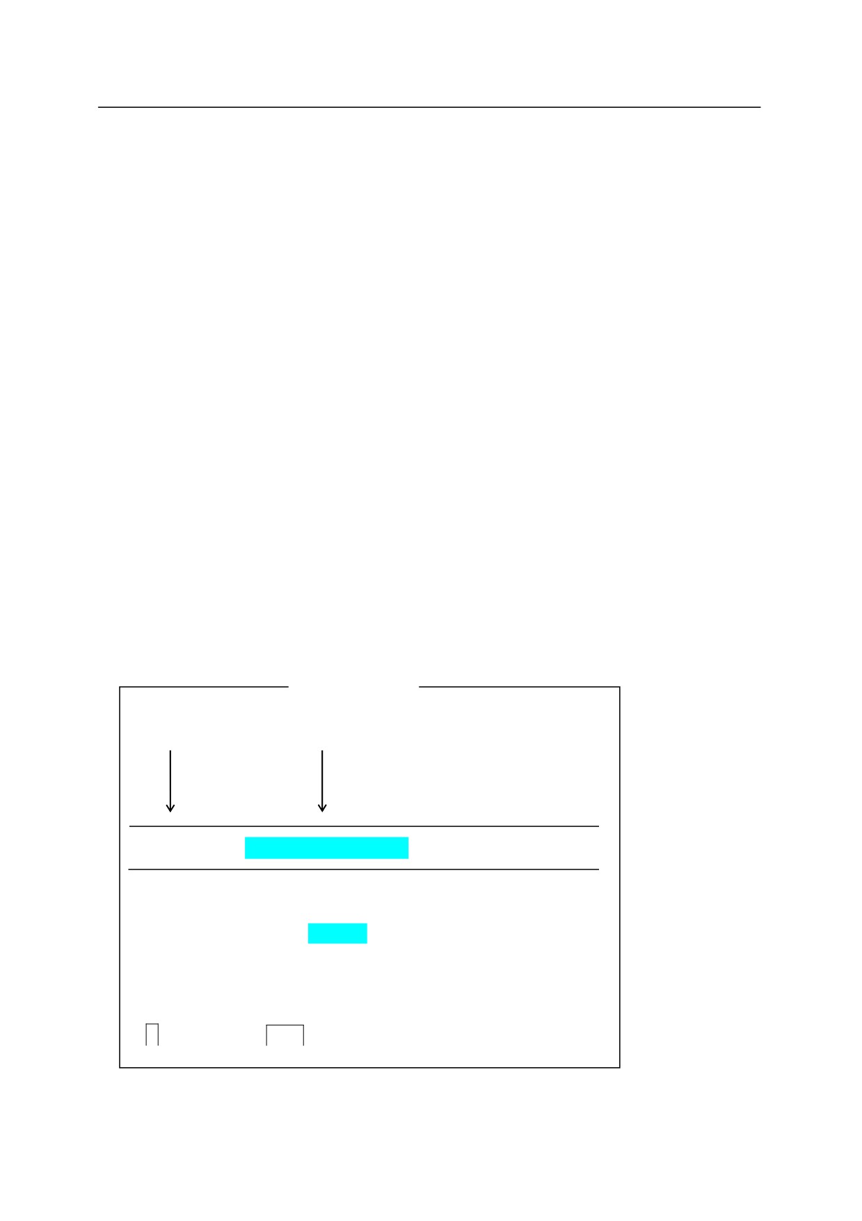
Example
Keyword
Parameter
PCSTATUS PC program number
Parameters marked with
can be omitted.
Always enter a space between the keyword and the parameter.
represents the
Enter key in the examples.
10-1
10. PC Programs
PCSTATUS PC program number:
Function㻌
Displays the status of PC programs. (M)
Parameter㻌
PC program number
Selects the PC program number to display. Acceptable range: 1 to 5.
If not specified, 1 is
assumed.
Explanation㻌
The PC program status is displayed in the following format.
(1) ······· PC status:
Program is not running
Execution cycles:
(2) ············· Completed cycles: 11
(3) ············· Remaining cycles: Infinite
(4) ············· Program name
Prio Step No.
(5) ············· pc_test0
1
PRINT "step1"
(1) Program status
The PC program status as described as one of the following:
Program is not running
Program is not currently running.
Program running
Program is currently running.
Program WAIT
Program is running, but waiting for the condition set in WAIT
command to fulfill.
(2) Completed cycles
Displays the number of execution cycles completed.
(3) Remaining cycles
Displays the numbers of cycles not yet executed. If the execution cycle is set as negative
number (1) in PCEXECUTE command, the display will be “infinite”.
(4) Program name
(5) Step
Displays the number of the step currently being executed and the instruction written in that step.
10-2
10. PC Programs
PCEXECUTE PC program number : program name䠈
execution cycle, step number
㻌
Function㻌
Executes PC programs.
(M, P)
Parameter㻌
PC Program number
Selects the number of the PC program to execute. Acceptable range: 1 to 5. If not specified,
1 is assumed. Up to 5 PC programs can be executed at the same time. The PC program
number is not the order of priority.
Program name
Selects the name of the program to execute at that PC program number. If not specified, the
program last executed using the PCEXECUTE command is selected.
Execution cycle
Specifies how many times the PC program is to be executed. If not specified, 1 is assumed. If
1 is entered, the program is executed continuously.
Step number
Selects the step from which to start execution. If not specified, the execution starts from the first
step in the program.
Explanation㻌
This command is identical to EXECUTE monitor command, except that this command executes
PC programs instead of robot control programs. The PC program currently in execution is
displayed with a blinking “ ” at the end of its name.
PCEXECUTE can be used as either a monitor command or an instruction in a robot control
program.
Example㻌
PCEXECUTE control, -1
The program “control” is executed continuously; i.e. program
execution continues until PCABORT command is executed,
PAUSE or HALT instruction is executed in the program, or
an error occurs.
10-3

10. PC Programs
㻌
PCABORT PC program number:㻌
Function㻌
Stops the execution of the currently running program. (M, P)
Parameter㻌
PC program number
Selects the number of the PC program to be stopped. Acceptable range: 1 to 5. If not specified,
1 is assumed.
Explanation㻌
PCABORT is identical to ABORT command except this command stops PC programs instead of
robot control programs.
The program currently running is stopped, and the execution can be resumed using
PCCONTINUE command.
PCABORT can be used as either a monitor command or an instruction in a robot control
program.
PCKILL PC program number:
Function㻌
Initializes the stack of PC programs. (M)
Parameter㻌
PC program number
Selects the number of the PC program to initialize. Acceptable numbers are from 1 to 5. If not
specified, 1 is assumed.
Explanation
This command initializes the program stack of PC programs.
When a program is suspended by PAUSE or PCABORT command, or by an error, the program
remains in the program stack. As long as the program is in the stack, it cannot be deleted
(DELETE command). In this case, first use PCKILL to remove the program from the stack.
10-4
10. PC Programs
PCEND PC program number: task number㻌
Function㻌
Ends execution of the PC program currently running upon execution of the next STOP instruction
in that program. (M, P)
Parameter㻌
PC program number
Selects the number of the PC program to end. Acceptable range: 1 to 5. If not specified, 1 is
assumed.
Task number
Specifies 1 or 1. If not specified, 1 is assumed.
Explanation㻌
If the task number is not specified or specified as 1, the program execution is stopped as soon as
the next STOP or RETURN instruction (or similar instruction) is executed, regardless of
remaining cycles. The remaining cycles can be executed using PCCONTINUE.
If 1 is specified as the task number, the PCEND command entered previously is canceled.
When a program loop occurs or the program runs infinitely without a STOP instruction, PCEND
is ineffective and must be canceled by PCEND 1.
(To cancel the loop, PCABORT must be
used).
PCEND can be used as either a monitor command or an instruction in robot control programs.
10-5
10. PC Programs
PCCONTINUE PC program number 㻌 NEXT
Function㻌
Resumes execution of a suspended PC program. Or, skips the WAIT instruction in the PC
program. (M)
Parameter㻌
PC program number
Selects the number of the PC program to resume execution. Acceptable range: 1 to 5. If not
specified, 1 is assumed.
NEXT
If this parameter is specified, the execution is resumed from the step after the step that was
suspended. If not specified, the execution resumes from the same step that was suspended.
With the parameter NEXT, this command can be used to skip the WAIT instruction in the
currently running PC program and to resume execution of that PC program.
Explanation㻌
PCCONTINUE is identical to CONTINUE command except this command is used to continue
execution of PC programs instead of robot control programs.
Execution is resumed from the step where the execution was stopped by PAUSE or PCABORT
command, or by an error, and from the step after that when the parameter NEXT is specified.
10-6
10. PC Programs
PCSTEP PC program number: program name䠈execution cycles䠈
step number
Function㻌
Executes a single step of a PC program. (M)
Parameter㻌
PC program number
Selects the number of the PC program containing the desired step. Acceptable range: 1 to 5. If
not specified, 1 is assumed.
Program name
Selects the name of the program to execute at that PC program number. If not specified, the
program currently in execution or the program last executed is selected.
Execution cycle
Specifies how many times the program step is to be executed. If not specified, 1 is assumed.
Step number
Selects the number of the program step to execute. If not specified, the first step of the program
is selected. If none of the parameters are specified, the next step is executed.
Explanation㻌
PCSTEP command, like the PCCONTINUE command, can be used without parameters only in
the following conditions:
1. when PCSTEP command was used in the last executed step
2. after a PAUSE instruction
3. when the program was suspended by reasons other than error.
Example㻌
>PCSTEP sequence,,23
Executes step 23 of the PC program no.1 named
“sequence” one time.
Enter PCSTEP
after this, and then the next step (step 24) is executed.
10-7
10. PC Programs
PCSCAN time
Function㻌
Sets the cycle time for executing the PC program. (P)
Parameter㻌
Time
Sets how long the program repetition cycle takes. The time is specified in seconds, 0 or greater.
Explanation㻌
This command is used to execute the PC program in the specified cycle time. If the execution
time is longer than the specified time, the time specified here is ignored.
Example㻌
program
PCSCAN 1
IF sig(1) THEN
SIGNAL -1
ELSE
SIGNAL 1
END
If the above program is executed continuously using the PCEXECUTE command (execution
cycle: 1), SIGNAL 1 turns ON OFF every second.
㻌
10-8
11. Sample Programs
Kawasaki Robots AS Language Reference Manual
11.0 SAMPLE PROGRAMS
This chapter shows some sample programs using the AS language system.
11.1 INITIAL SETTINGS FOR PROGRAMS
For easier programming, the settings below are done prior to performing any function on the
robot.
· Move the robot to the home pose.
· Define the necessary variables for each task. (e.g. for palletizing, fix the number of parts per
pallet)
· Initialize counter, flag, etc.
· Set the tool coordinates to be used in this task.
· Set the base coordinates to be used in this task.
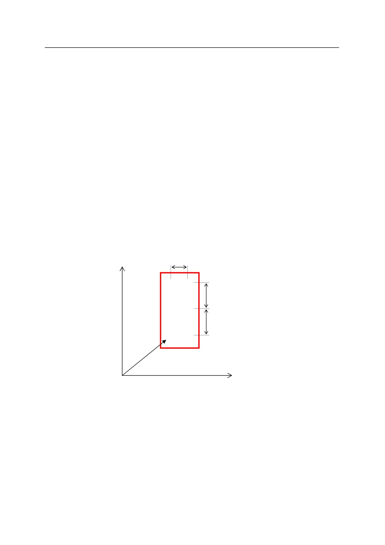
Here is an example of a program initialization routine for a palletizing operation as shown in
the figure below.
Y
100
(5)
(6)
150
(3)
(4)
150
(1)
(2)
Pallet
start
X
In the above example, parts are palletized in order from (1) to (6). In this case, a program
like the following should be used for initial setting. The pallet is set parallel to the robot base
coordinates in this example.
1 BASE NULL
;defines the robot base coordinate (NULL)
2 TOOL tool1
;tool transformation (tool1)*
3 row.max=3
;3 rows
4 col.max=2
;2 columns
5 xs=100
;sets the allocation distance in the X coordinate(X=100mm)
6 ys=150
;sets the allocation distance in the Y coordinate (Y=150mm)
7 POINT put=start
;substitutes the value of pose(1) to variable put.
11-1
11. Sample Programs
Kawasaki Robots AS Language Reference Manual
8 OPENI
;opens the hand of the tool
9 HOME
;moves to home pose**
Note* The tool transformation values (tool 1) should be defined prior to proceeding.
Note ** The origin (HOME) should be defined prior to proceeding.
11-2
11. Sample Programs
Kawasaki Robots AS Language Reference Manual
11.2 PALLETIZING
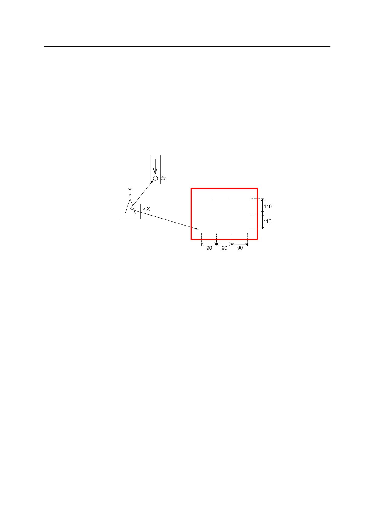
In the example shown here, parts are picked up from a parts feeder and placed on a pallet with
three rows (110 mm apart) and four columns (90 mm apart). To simplify the explanation,
both the pallet and the parts placed on the pallet are set parallel to the XY plane of the robot
base coordinates. Also, the procedure of synchronizing the feeder and the robot using the
external I/O signals (SWAIT instruction, SIGNAL instruction, etc.) is omitted.
Parts feeder
Pallet
(9)
(10)
(11)
(12)
(5)
(6)
(7)
(8)
Robot
start
(1)
(2)
(3)
(4)
· The pallet is set parallel to the XY plane of the base coordinates.
· Pose #a (Parts feeder) and pose “start” (where the first part is placed) are to be defined prior
to executing the program.
11-3
11. Sample Programs
Kawasaki Robots AS Language Reference Manual
Program Example
.PROGRAM palletize
;
initial setting (3 rows, 4 columns, X=90, Y=110, etc.)
row.max=3
col.max=4
xs=90
ys=110
SPEED 100 ALWAYS
ACCURACY 100 ALWAYS
POINT put=start
OPENI
;
;
Start palletizing
FOR row=1 TO row.max
FOR col=1 TO col.max
JAPPRO #a,100
SPEED
30
ACCURACY 1
Picks up the part from the feeder.
LMOVE
#a
CLOSEI
LDEPART 200
;
JAPPRO put, 200
SPEED
30
ACCURACY 1
Places the part on the pallet.
LMOVE put
OPENI
LDEPART 200
;
;
Calculate the pose of part in the next row.
POINT put=SHIFT(put BY xs, 0,0)
END
;
;
Calculate the pose of part in the next column.
POINT put=SHIFT(start by 0,ys*row, 0)
END
.END
11-4
11. Sample Programs
Kawasaki Robots AS Language Reference Manual
11.3 EXTERNAL INTERLOCKING
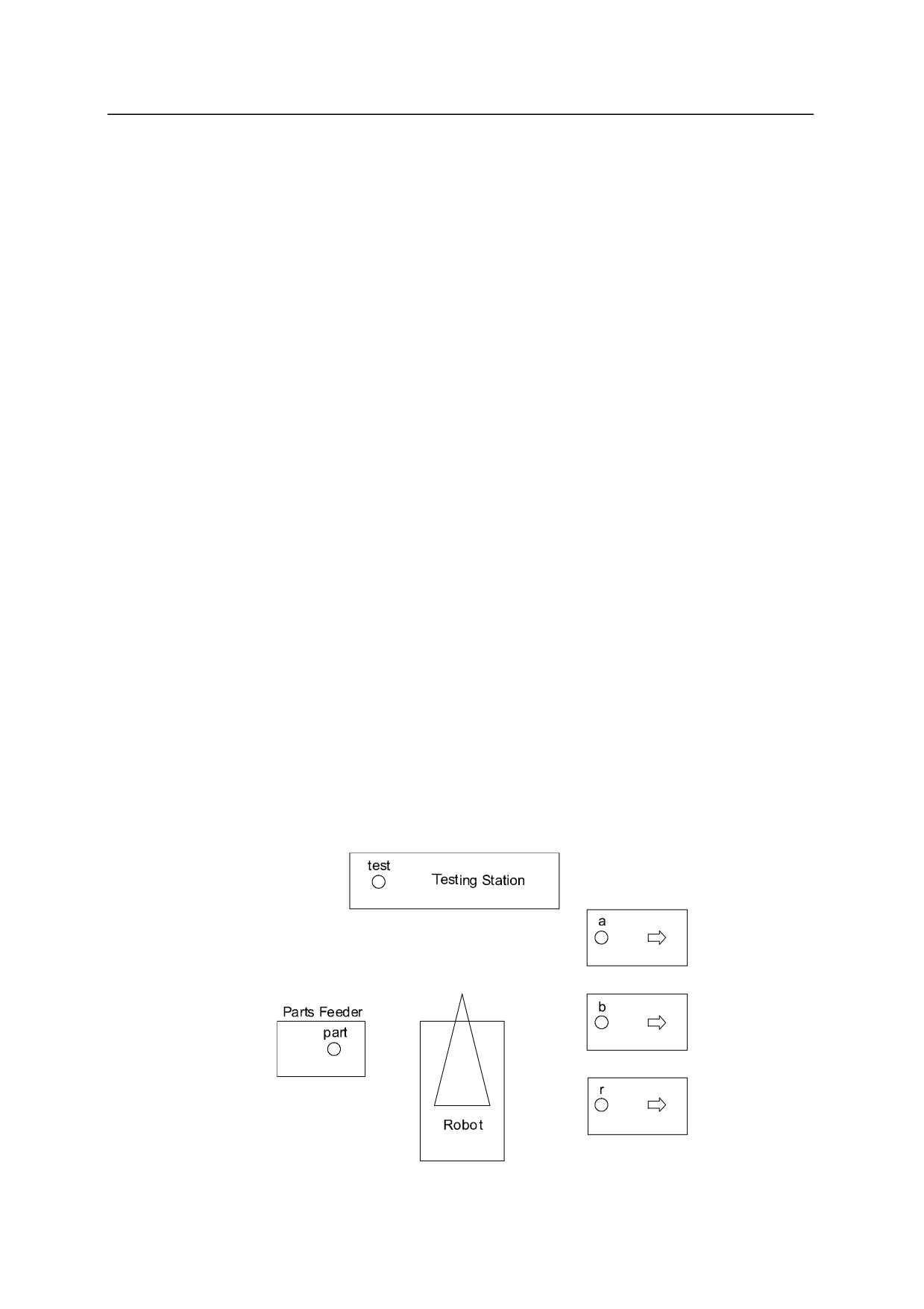
This example demonstrates an operation performed synchronously with an external device.
This program uses the instructions: SIGNAL, IF, SWAIT, ONI, IGNORE.
1. Two types of parts, A and B, are set in the Parts Feeder in random order.
(Input signal
for set complete: IN1)
2. The robot picks up a part from the Parts Feeder and sets it at the Testing Station.
(Output signal for set complete: OUT1)
3. At the Testing Station, the parts are classified into part A, part B or other than A or B.
Input signal for testing complete: IN2
Input signal for parts classification: IN3, IN4
(IN3, IN4) = (1, 0)
:
part A
(IN3, IN4) = (0, 1)
:
part B
(IN3, IN4) = (0, 0) or (1, 1)
:
Others
4. The robot places the parts according to the classification of each part.
If any trouble arises with the Testing Station while the robot picks up the part from the feeder
and carries it to the Testing Station, the program immediately halts and branches to the trouble
shooting subroutine. The external input signal for trouble occurrence is IN7. The signal
IN6 is input when trouble shooting is completed, and the robot resumes execution as soon as
this signal is input.
The program to perform the above operation is named MAIN, the trouble shooting subroutine
is named EMERGENCY.
Part A
Part B
Others
11-5
11. Sample Programs
Kawasaki Robots AS Language Reference Manual
Program Example
; Define Variables
set.end =1001
;signal for set complete (IN1) is named set.end
test.end =1002
;signal for test complete (IN2) is named test.end
a.part
=1003
;signal for part A (IN3) is named a.part
b.part
=1004
;signal for part B (IN4) is named b.part
retry
=1006
;signal for trouble resolved(IN6) is named retry
fault=1007
;signal for trouble (IN7) is named fault
test.start= 1
;signal for start test (OUT1) is named test.start
.PROGRAM main()
OPENI
10 JAPPRO part,100
ONI fault CALL emergency
;monitors for signal fault and jumps to emergency
subroutine when it is detected
SWAIT set.end
;waits for the part to be set in the feeder
LMOVE
part
;moves to part (Parts Feeder)
CLOSEI
LDEPART
100
JAPPRO
test,100
;carries the part to the Testing Station
LMOVE
test
BREAK
;
IGNORE
fault
;stops monitoring for signal IN7 (fault)
SIGNAL
test.start
;turns ON the signal test.start
TWAIT 1.0
SWAIT test.end
;waits until the testing is completed
JDEPART
100
SIGNAL
-test.start
;turns OFF the signal test.start
IF SIG(a.part,-b.part) GOTO 20
;if the part is part A, then jump to label 20
IF SIG(-a.part,b.part) GOTO 30
;if the part is part B, then jump to label 30
POINT n=r
;if it is neither A nor B, then carry the part to r
GOTO 40
20 POINT
n=a
;defines the place to put part A
GOTO 40
30 POINT
n=b
;defines the place to put part B
40 JAPPRO n,100
;carries part to its placing pose
11-6
11. Sample Programs
Kawasaki Robots AS Language Reference Manual
LMOVE
n
OPENI
LDEPART
100
GOTO 10
.END
.PROGRAM emergency()
PRINT "**ERROR**"
;outputs error message on the terminal
SWAIT retry
;waits until the trouble is resolved
ONI fault CALL emergency
;starts monitoring for fault again,
RETURN
;returns to the main program
.END
11-7
11. Sample Programs
Kawasaki Robots AS Language Reference Manual
11.4 TOOL TRANSFORMATIONS
This section explains how to obtain tool transformation values and how to create programs
using them.
11.4.1 TOOL TRANSFORMATION VALUES-1 (WHEN THE TOOL SIZE IS
UNKNOWN)
When the size of the tool is unknown due to awkwardness of the tool, tool transformation
values can be calculated as shown below. The Z axis of the base coordinates is set
perpendicular to the ground.
1. Select an object with a sharp point. Fix the tip of the object pointing up vertically from
the ground. This point will be the reference point “r”.
Reference point r
2. Move the robot so that the tool mounting flange faces straight downward. Then in repeat
mode, enter the following commands:
>SPEED 10
>TOOL NULL
;sets the tool coordinates to be null
>DO ALIGN
;align the tool Z axis with the base Z axis
3. Using the Base Mode on the teach pendant, move the robot so that the center of the flange
is perpendicular to the reference point. Next, move the robot moving only along X, Y, Z
of the base coordinates.
Enter as below so that the transformation values for that pose
is assigned to variable “a”:
>HERE a
a
Reference point r
Base coordinates
11-8
11. Sample Programs
Kawasaki Robots AS Language Reference Manual
4. Install the tool to the flange, and move the tool center point (TCP) to the reference point so
that the Z axis of the new tool coordinate is perpendicular to the X and Y axes of base
coordinates.
Enter as below to teach the transformation values at that pose as compound values “a+b”:
>HERE a+b
b
a+b
Reference point r
a
Base coordinates
5. From these compound values, the tool transformation values can be found as “-b”.
Enter:
>POINT t=-b
This assigns the values of -b to the variable t.
6. Specify the tool transformation as t.
>TOOL t
7. To check, enter as following:
>DO JMOVE r
The tool tip should move to the reference point r.
Once defined, all performances are based on this tool transformation, unless the tool is
changed.
11-9
11. Sample Programs
Kawasaki Robots AS Language Reference Manual
11.4.2 TOOL TRANSFORMATION VALUES-2 (WHEN THE TOOL SIZE IS
KNOWN)
When the tool size is known, the tool transformation values can be obtained as shown below.
Values determined by this procedure are generally more accurate than those obtained in the
former procedure. (See above 11.4.1)
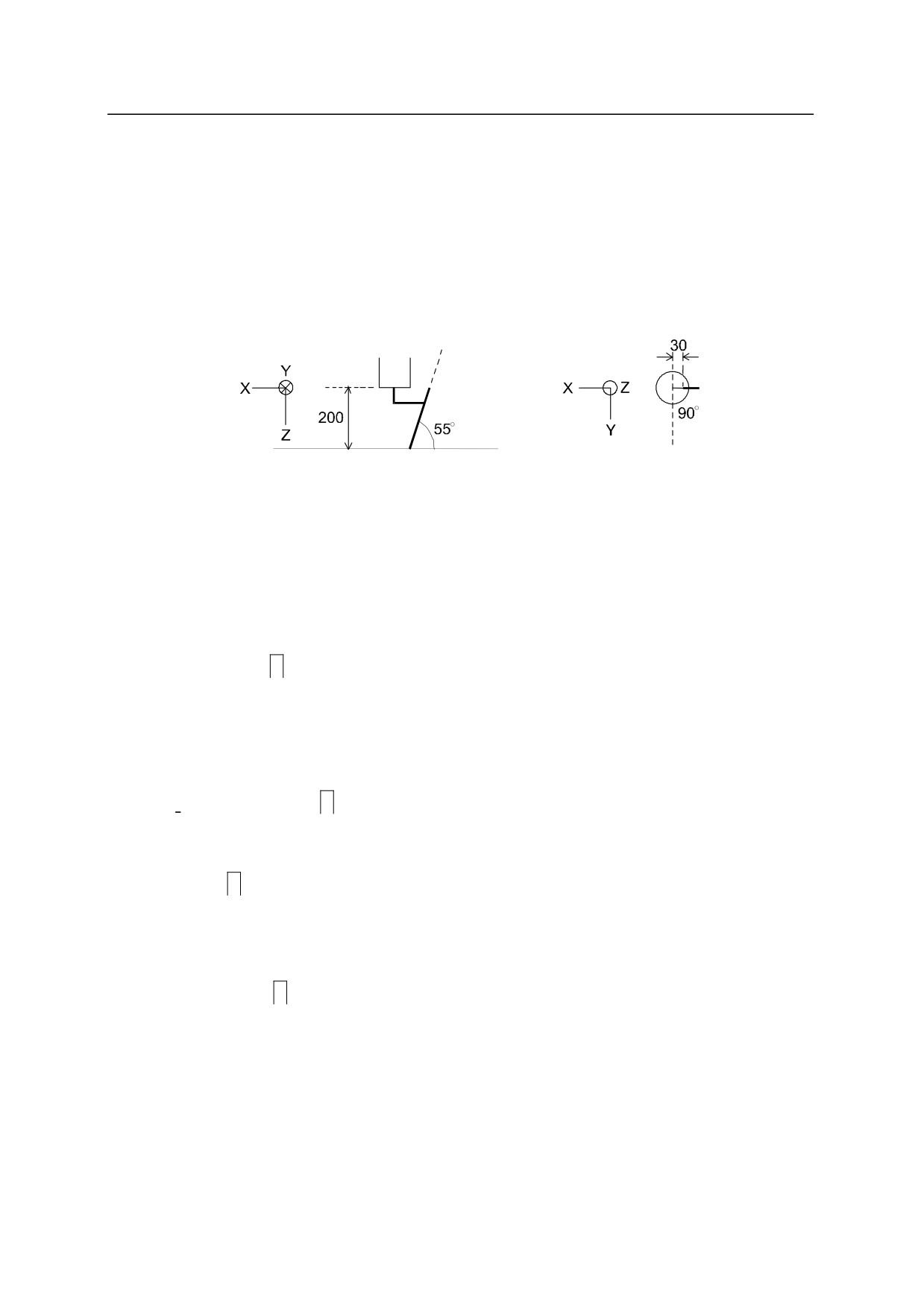
The XYZ axes in the above figure express the null tool coordinate. The following procedure
sets tool coordinate origin at the tip of the torch and the Z axis in the same direction as the
torch.
(1)Define the tool transformation value variable “torch” using the POINT command:
>POINT torch
X
Y
Z
O
A
T
0
0
0
0
0
0
Change
>-30, 0, 200, 0, 35, 0
X
Y
Z
O A T
-30
0
200
0
35
0
Change
>
(2) Set the tool transformation values using the variable “torch”.
>TOOL torch
11-10
11. Sample Programs
Kawasaki Robots AS Language Reference Manual
11.5 RELATIVE POSES
11.5.1 USAGE OF RELATIVE POSES
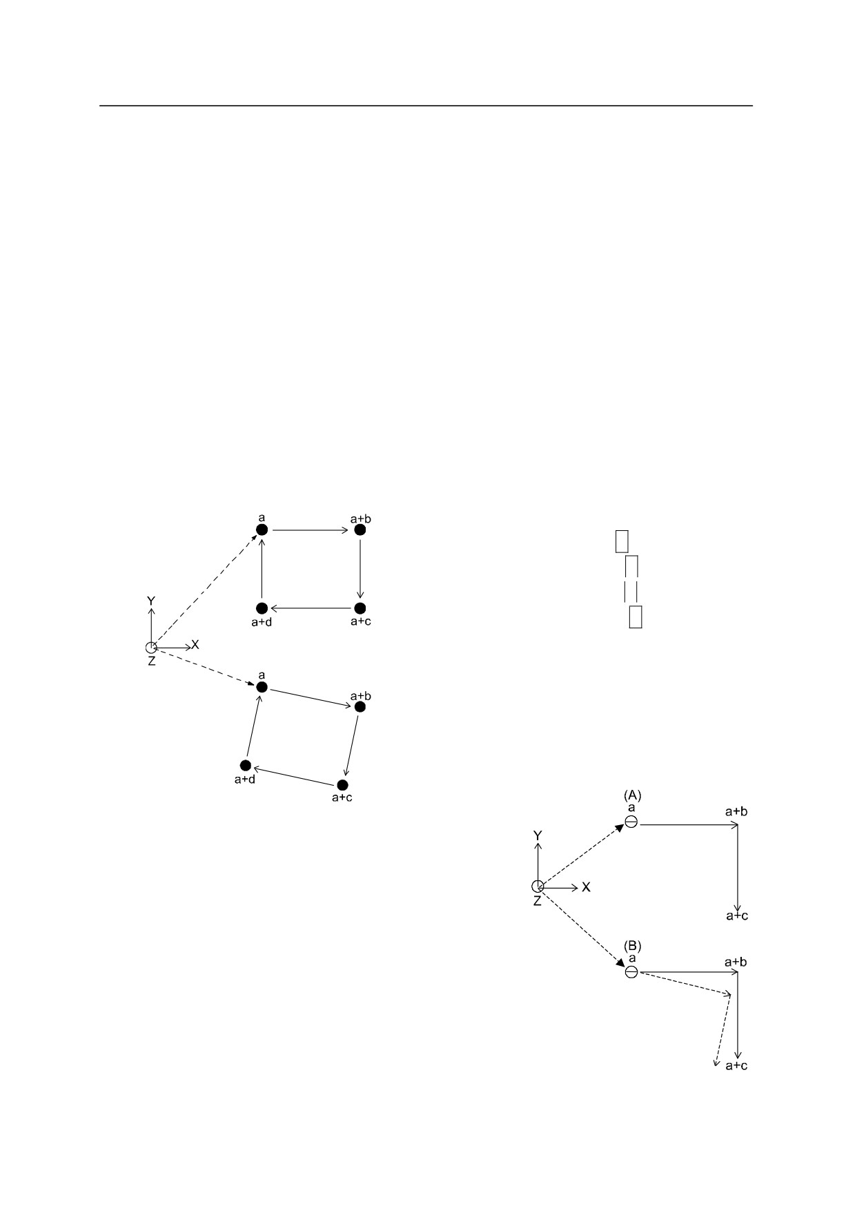
A pose can be defined relative to a reference point. When defined in this way, the relation
between that pose and the reference point remains consistent even if the reference point is
redefined.
For example, when the four corners of a table are taught, the pose relation between the robot
and the table changes depending on where they are placed, but as long as the shape of the table
remains the same, the relation of the four corners does not change. Therefore, if one of the
corners is taught as a reference point for specifying the absolute pose relation between the
robot and the table, and the other three corners are taught relative to the first corner, then,
when the table is relocated, only the reference point has to be redefined.
Example
Teaching
>HERE a
>HERE a+b
>HERE a+c
>HERE a+d
Program
JMOVE a
LMOVE a+b
LMOVE a+c
LMOVE a+d
LMOVE a
In figure (A) on the right, the reference point a and
compound transformation values for the other corners
are taught. Then, in figure (B) the reference point a is
redefined. If the orientation of the robot tool
is not reset (i.e. kept at the same orientation as it was in (A)),
the robot will move in the trajectory shown in solid line.
If the robot is supposed to move along the dotted line,
it is necessary to redefine the orientation as well as the position.
11-11
11. Sample Programs
Kawasaki Robots AS Language Reference Manual
11.5.2 EXAMPLE OF PROGRAM USING RELATIVE POSES
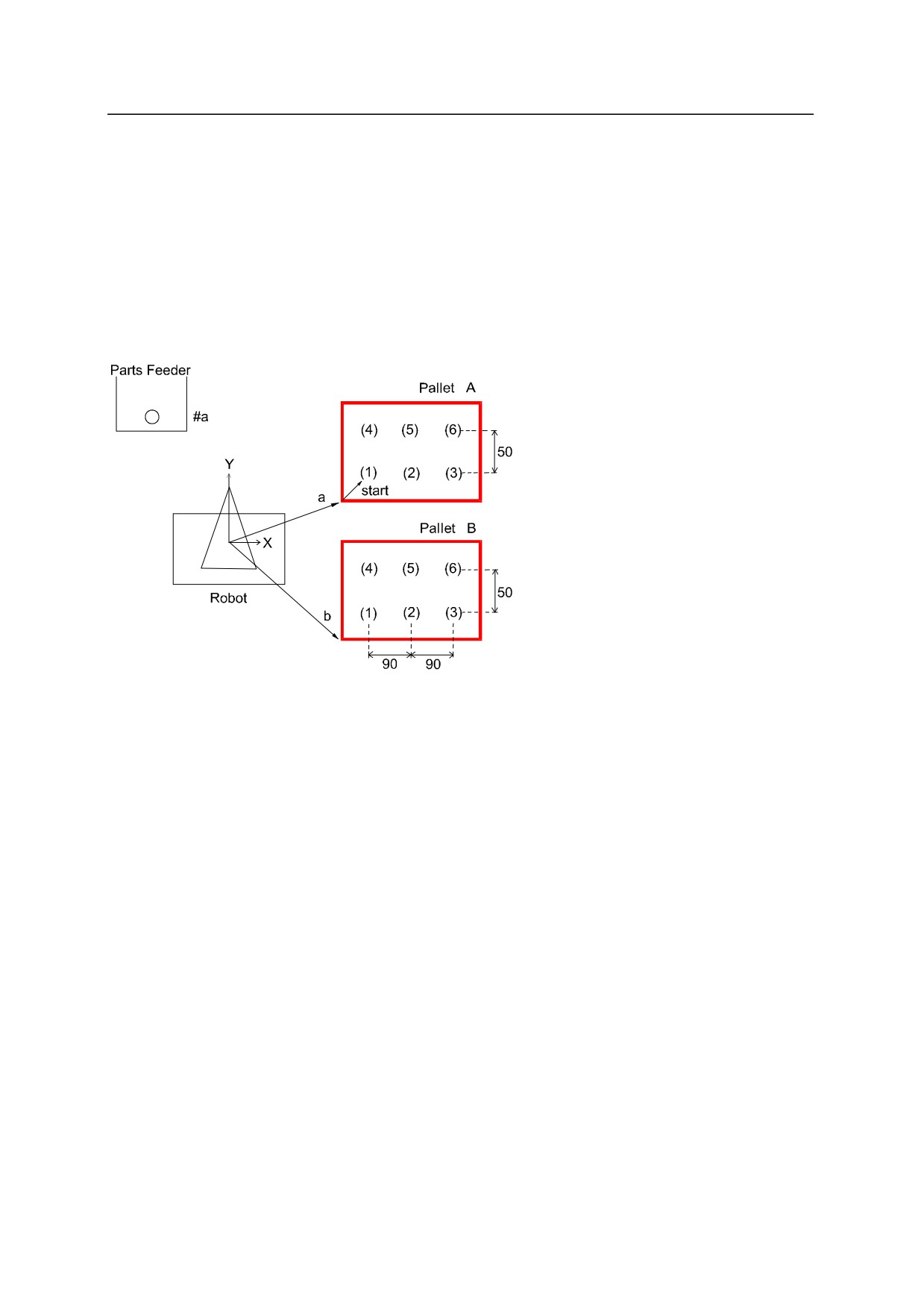
In this example, the parts are palletized as in the previous example except two pallets are used.
The pallets are placed separately but the relation between the reference point and the places
the parts are to be put are the same on either pallet. This operation sets the parts from the
Parts Feeder on to Pallet A. After six parts are set, the robot goes on to do the same with
Pallet B.
(The procedure of synchronizing with the Parts Feeder is omitted).
Poses to be taught
#a
: pose where robot picks up parts from the feeder
a
: reference pose on Pallet A
b
: reference pose on Pallet B
start
: pose of the first part on the pallet relative to the reference point
11-12
11. Sample Programs
Kawasaki Robots AS Language Reference Manual
Program example
.PROGRAM relative.test
;
Initial setting (2rows, 3columns, X=90, Y=50, etc.)
row.max=2
col.max=3
xs=90
ys=50
OPENI
flg=0
; flg=0䠖Pallet A, flg=1䠖Pallet B
POINT pallet=a
;
start palletizing
10
POINT put=start
FOR ro w1 TO row.max
FOR col=1 TO col.max
JAPPRO #a,100
LMOVE
#a
picks up the part from the feeder
CLOSEI
LDEPART 100
;
POINT put_pt=pallet+put
JAPPRO put pt,200
LMOVE put pt
places the part on the pallet
OPENI
LDEPART 200
;
POINT put=SHIFT(put BY xs,0,0)
;finds the place of the part on the next column
END
;
POINT put=SHIFT(start BY 0,ys*row,0)
;finds the place of the part on the next row
END
;
IF flg<>0 GOTO 30
; goes to finishing procedure when Pallet B is completed (flg=1)
flg=1
POINT pallet=b
;defines the reference pose of Pallet B
GOTO 10
30
TYPE "*** end ***"
STOP
.END
11-13
11. Sample Programs
Kawasaki Robots AS Language Reference Manual
11.6 RELATIVE POSE USING THE FRAME FUNCTION
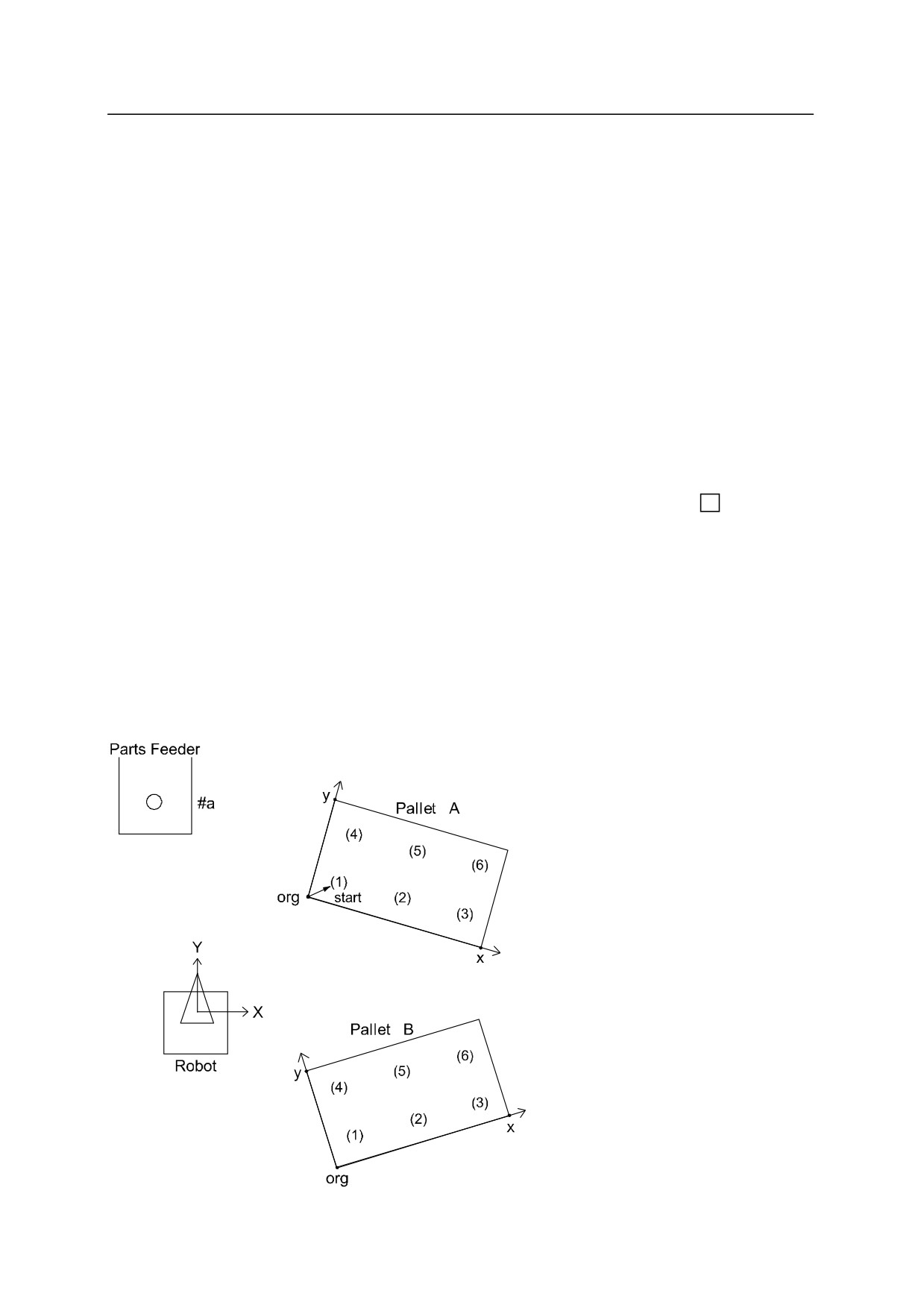
In the example in 11.5.1, the orientation of the tool had to be corrected when redefining the
reference pose. That is not necessary if the FRAME function is used. Teach four points (b,
c, d, e) to define the frame transformation value a. Points b and c determine the direction of
the X axis, the third point d determines the XY plane, and point e the origin. After the points
are taught, enter the following command:
POINT a=FRAME(b,c,d,e)
Then, the relative coordinates are defined as the variable “a”. The XYZ values shows the
position of the origin of the relative coordinate and the OAT values show the orientation of the
relative coordinates.
Hereafter, all the poses on the relative coordinates can be expressed as pose a+
If the
place of the pallet changes, teach b, c, d, e again to redefine a in the same manner as above.
The relative coordinates defined using the FRAME function are also called the FRAME
coordinates.
In the following sample program, the same operation as in 11.5.2 is performed using the frame
coordinates.
11-14
11. Sample Programs
Kawasaki Robots AS Language Reference Manual
The first procedure is to palletize the parts on Pallet A. Three corners of the pallet are taught,
one as the origin, another as a point on the X axis and another as a point on the Y axis (see
figure above). Execute the program below to palletize on Pallet A (note that after the points
are defined, the rest of the program is the same as the previous sample program). To
palletize on Pallet B, reteach the three corners and execute the same program. The frame
coordinates will be redefined and the parts will be palletized on Pallet B as on Pallet A.
Program Example
.PROGRAM frame.test
;
Initial setting (2 rows,3 columns, X=90, Y=50,etc.)
row.max=2
col.max=3
xs=90
yx=50
OPENI
;
POINT pallet=FRAME(org,x,y,org)
;defines the frame coordinates of the pallet.
;
(3 points: for origin, for X/Y axes)
POINT put=start
; starts palletizing.
FOR row=1 TO row.max
FOR col=1 TO col.max
JAPPRO
#a,100
LMOVE
#a
CLOSEI
picks up the part from the parts feeder.
LDEPART 100
;
POINT put pt=pallet+put
JAPPRO put pt,200
LMOVE put pt
places the part on the pallet.
OPENI
LDEPART 200
;
POINT put=SHIFT(put BY xs,0,0)
; finds the place of the part on the next column.
END
;
POINT put=SHIFT(startBY 0,ys*row,0)
; finds the place of the part on the next row.
END
STOP
.END
11-15
11. Sample Programs
Kawasaki Robots AS Language Reference Manual
11.7 SETTING ROBOT CONFIGURATIONS
Most robots have six joints, and when a pose is taught using the joint displacement values, the
displacement values of each of the six joints are given, so the pose of the robot is defined
uniquely. On the other hand, when a pose is defined using the transformation values, there
are cases, depending on the arm configuration of the robot, where more than one set of joint
values gives the same pose specified by one transformation values. In AS, the robot basically㻌
keeps the configuration of the previous action, so no change in the robot configuration is
needed. However, in the following cases, the robot’s configuration should be specified by a
configuration instruction:
1. When the robot moves from a point with unclear configuration to a point taught by
transformation values,
2. When the 5th joint (the bent joint) passes through the origin (0°) in a SBS wrist
configuration. (SBS: swivel, bend, swivel)
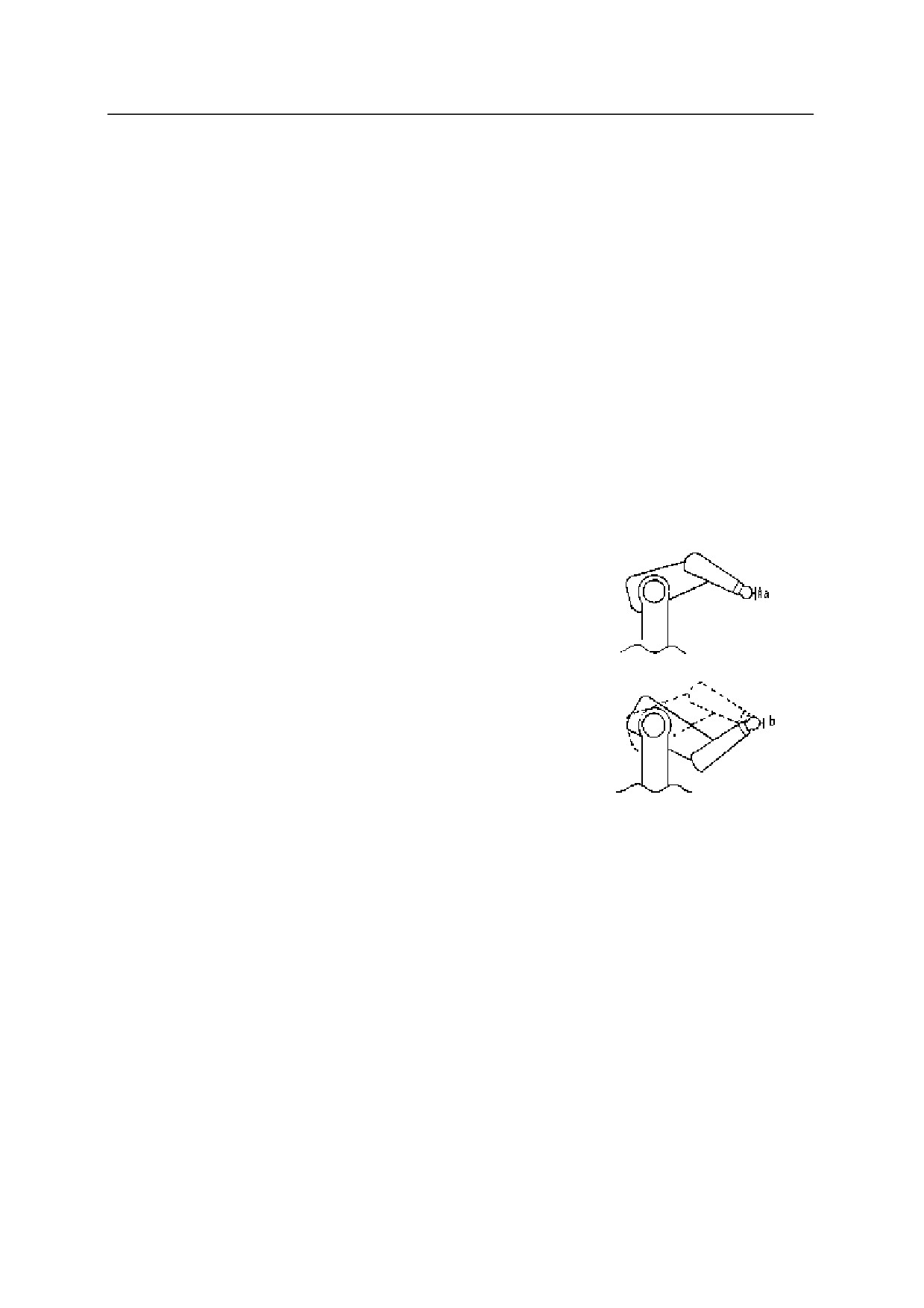
For example in the figure on the right,
if pose #a is defined with the configuration ABOVE
then the result of the instruction JMOVE b will be
ABOVE (dotted line in the figure) even if pose b is
originally defined BELOW.
JMOVE
#a
JMOVE b
In the same way, if #a is defined UWRIST (JT5>0),
the configuration at pose b will be UWRIST regardless
of the configuration when that pose was taught.
To solve these problems, it is necessary to change the robot’s configuration while it is in
motion. Do this by executing a configuration instruction whenever a joint motion instruction
ends in a point defined with transformation values (joint interpolated motion instructions:
JMOVE, JAPPRO, JDEPART, DRIVE etc.). Six configuration instructions are listed here, a
program example is given in the note box on the following pages.
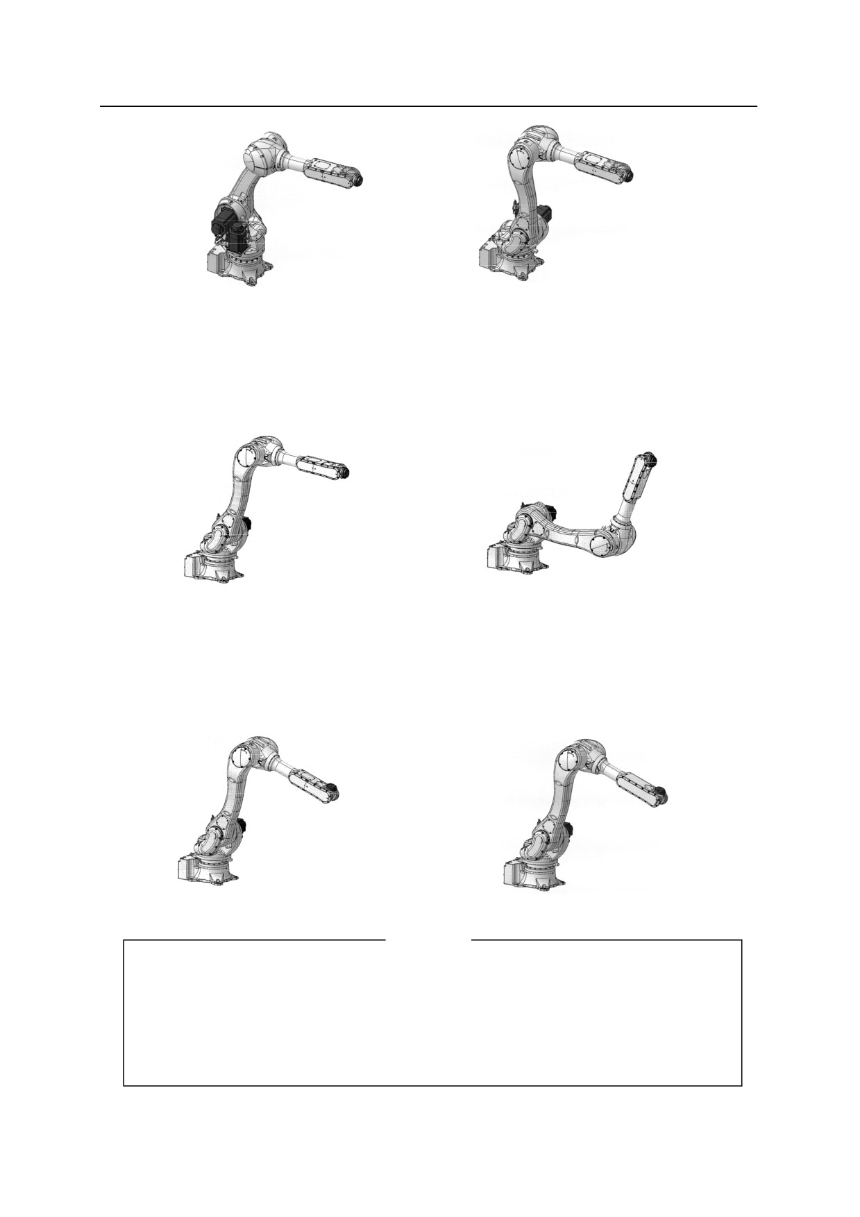
LEFTY, RIGHTY
Sets the configuration of the first three joints (JT1, JT2, JT3) of the robot. LEFTY sets the
robot configuration to resemble a person’s left arm, RIGHTY to resemble a right arm.
11-16
11. Sample Programs
Kawasaki Robots AS Language Reference Manual
LEFTY
RIGHTY
ABOVE, BELOW
Sets the robot configuration so that the third joint (JT3) is in the above position (ABOVE), or
below position (BELOW).
ABOVE
BELOW
UWRIST, DWRIST
Sets the configuration of the robot so that the value of the fifth joint (JT5) is positive
(UWRIST) or negative (DWRIST) to acquire the same tool orientation.
UWRIST
DWRIST
[ NOTE ]
1. Generally, configuration instructions do not have effect on joint displacement
values (poses named with #), and the robot moves to the taught position in taught
configuration. However, it results in an error when moving the robot in linear
interpolated motion between poses where the configuration at the beginning differs
from the configuration at the destination.
11-17

11. Sample Programs
Kawasaki Robots AS Language Reference Manual
2. The robot does not react immediately to a configuration instruction. The
configuration changes while executing the next joint interpolated motion (JMOVE,
JAPPRO, JDEPART, DRIVE etc.).
3. In regular programs, the configuration does not have to be changed except when it
is changed on purpose. The configuration instructions are used in the following
cases:
(1) When a program does not start with a motion instruction that moves the robot to a
pose defined by joint displacement values, a configuration instruction should be
written in the beginning of the program to determine the robot’s configuration.
(2) When the JAPPRO instruction is used as below, configuration instruction should
be used:
JMOVE a
JAPPRO
#b,100
JMOVE
#b
The configuration after executing the motion instruction “JAPPRO #b,100” may, in
some cases , differ from the configuration at #b. If the configuration of the wrist
(the of the angle of JT5) is different, executing the next step, “JMOVE #b”, may
cause JT4 and JT6 to rotate greatly. A way to avoid this is to teach a pose 100
mm above pose #b as #bb and use the JMOVE instruction as follows:
JMOVE a
JMOVE
#bb
JMOVE
#b
:
Another way to avoid the large motion amount of JT4 and JT6 is to specify the wrist
configuration using the configuration instruction. In this example, configuration in
#b is assumed to be UWRIST (value of JT5 is positive).
JMOVE a
UWRIST
JAPPRO
#b,100
JMOVE
#b
:
The configuration of the wrist changes to UWRIST after “JAPPRO #b, 100” is
executed, thus avoiding unnecessary rotation of joints 4 and 6 at execution of
“JMOVE #b”.
11-18

Appendix 1 Limitation of Signal Numbers
APPENDIX 1 LIMITATION OF SIGNAL NUMBERS
No
M, P, F*
Output Signals
Input Signals
Internal Signals
1
BITS
M
1 to maxsig**
------
2001 to maxsig**
P
2
BITS
F
1 to maxsig**
1001 to maxsig**
2001 to maxsig**
3
DEFSIG
M
1 to maxsig**
1001 to maxsig**
------
4
DLYSIG
M
1 to maxsig**
------
2001 to maxsig**
P
5
ON, ONI
P
------
1001 to 1256***
2001 to 2256
6
PULSE
M
1 to maxsig**
------
2001 to maxsig**
P
7
RUNMASK
P
1 to 64**
------
2001 to maxsig**
8
SIGNAL
M
1 to maxsig**
------
2001 to maxsig**
P
9
SIG
F
1 to maxsig**
1001 to maxsig**
2001 to maxsig**
10
SWAIT
P
1 to maxsig**
1001 to maxsig**
2001 to maxsig**
11
XMOVE
P
------
1001 to 1256***
2001 to 2256
12
13
NOTE * M= monitor command, P= program instruction, F= function
NOTE ** maxsig: number of I/O signals installed
32 (standard), maximum 960 (option)
NOTE*** Although marked as 1 to 256 or 1001 to 1256, the maximum number that can
be specified is 32(1032) if the standard I/O module is installed.
A1-1

Appendix 2 ASCII Codes
APPENDIX 2
ASCII CODES
ASCII
Hexa-
Octal
Decimal
Description
character
decimal
NULL
000
00
00
Null
SOH
001
01
01
Start of heading
STX
002
02
02
Start of text
ETX
003
03
03
End of text
EOT
004
04
04
End of transmission
ENQ
005
05
05
Enquiry
ACK
006
06
06
Acknowledge
BEL
007
07
07
Bell
BS
010
08
08
Backspace
HT
011
09
09
Horizontal tabulation
LF
012
10
0A
Line feed
VT
013
11
0B
Vertical tabulation
FF
014
12
0C
Form feed
CR
015
13
0D
Carriage return
SO
016
14
0E
Shift out
SI
017
15
0F
Shift in
DLE
020
16
10
Data link escape
DC1
021
17
11
Device control 1
DC2
022
18
12
Device control 2
DC3
023
19
13
Device control 3
DC4
024
20
14
Device control 4
NAK
025
21
15
Negative acknowledge
SYN
026
22
16
Synchronous idle
ETB
027
23
17
End of transmission block
CAN
030
24
18
Cancel
EM
031
25
19
End of medium
SUB
032
26
1A
Substitute
ESC
033
27
1B
Escape
FS
034
28
1C
File separator
GS
035
29
1D
Group separator
RS
036
30
1E
Record separator
US
037
31
1F
Unit separator
SP
040
32
20
Space
A2-1

Appendix 2 ASCII Codes
ASCII
Hexa-
ASCII
Hexa-
Octal
Decimal
Octal
Decimal
character
decimal
character
decimal
040
32
20
0
060
48
30
!
041
33
21
1
061
49
31
”
042
34
22
2
062
50
32
#
043
35
23
3
063
51
33
$
044
36
24
4
064
52
34
%
045
37
25
5
065
53
35
&
046
38
26
6
066
54
36
’
047
39
27
7
067
55
37
(
050
40
28
8
070
56
38
)
051
41
29
9
071
57
39
052
42
2A
:
072
58
3A
+
053
43
2B
;
073
59
3B
‘
054
44
2C
<
074
60
3C
055
45
2D
=
075
61
3D
056
46
2E
>
076
62
3E
/
057
47
2F
?
077
63
3F
A2-2

Appendix 2 ASCII Codes
ASCII
Hexa-
ASCII
Hexa-
Octal
Decimal
Octal
Decimal
character
decimal
character
decimal
@
100
64
40
140
96
60
A
101
65
41
a
141
97
61
B
102
66
42
b
142
98
62
C
103
67
43
c
143
99
63
D
104
68
44
d
144
100
64
E
105
69
45
e
145
101
65
F
106
70
46
f
146
102
66
G
107
71
47
g
147
103
67
H
110
72
48
h
150
104
68
I
111
73
49
i
151
105
69
J
112
74
4A
j
152
106
6A
K
113
75
4B
k
153
107
6B
L
114
76
4C
l
154
108
6C
M
115
77
4D
m
155
109
6D
N
116
78
4E
n
156
110
6E
O
117
79
4F
o
157
111
6F
P
120
80
50
p
160
112
70
Q
121
81
51
q
161
113
71
R
122
82
52
r
162
114
72
S
123
83
53
s
163
115
73
T
124
84
54
t
164
116
74
U
125
85
55
u
165
117
75
V
126
86
56
v
166
118
76
W
127
87
57
w
167
119
77
X
130
88
58
x
170
120
78
Y
131
89
59
y
171
121
79
Z
132
90
5A
z
172
122
7A
[
133
91
5B
173
123
7B
¥
134
92
5C
174
124
7C
]
135
93
5D
175
125
7D
136
94
5E
176
126
7E
137
95
5F
DEL
177
127
7F
A2-3