Sun Microsystems System Administration Guide, Volume 1 (2000) - page 10

# cfgadm -c configure c1::dsk/c1t4d0
4. Verify the SCSI device is configured.
# cfgadm -al
Ap_Id
Type
Receptacle
Occupant
Condition
c0
scsi-bus
connected
configured
unknown
c0::dsk/c0t0d0
disk
connected
configured
unknown
c0::rmt/0
tape
connected
configured
unknown
c1
scsi-bus
connected
configured
unknown
c1::dsk/c1t3d0
disk
connected
configured
unknown
c1::dsk/c1t4d0
disk
connected
configured
unknown
How to Disconnect a SCSI Controller
Disconnecting a SCSI device must be done with caution, particularly when dealing
with controllers for disks containing critical file systems such as root (/), usr, var,
and the swap partition. The dynamic reconfiguration software cannot detect all cases
where a system hang may result. Use this command with caution.
SCSI controller c1 provides an example of disconnecting a SCSI device.
1. Become superuser.
2. Verify the device is connected before disconnecting it.
# cfgadm -al
Ap_Id
Type
Receptacle
Occupant
Condition
c0
scsi-bus
connected
configured
unknown
c0::dsk/c0t0d0
disk
connected
configured
unknown
c0::rmt/0
tape
connected
configured
unknown
c1
scsi-bus
connected
configured
unknown
c1::dsk/c1t3d0
disk
connected
configured
unknown
c1::dsk/c1t4d0
disk
connected
configured
unknown
3. Disconnect a SCSI controller.
Configuring Devices
299
# cfgadm -c disconnect c1
WARNING: Disconnecting critical partitions may cause system hang.
Continue (yes/no)? y
Caution - This command suspends all I/O activity on the SCSI bus until the
cfgadm -c connect command is used. The cfgadm command does some basic
checking to prevent critical partitions from being disconnected, but it cannot detect
all cases. Inappropriate use of this command may result in a system hang and could
require a system reboot.
4. Verify the SCSI bus is disconnected.
# cfgadm -al
Ap_Id
Type
Receptacle
Occupant
Condition
c0
scsi-bus
connected
configured
unknown
c0::dsk/c0t0d0
disk
connected
configured
unknown
c0::rmt/0
tape
connected
configured
unknown
c1
unavailable
disconnected configured
unknown
c1::dsk/c1t10d0
unavailable
disconnected configured
unknown
c1::dsk/c1t4d0
unavailable
disconnected configured
unknown
The controller and all the devices attached to it are disconnected from the system.
How to Connect a SCSI Controller
SCSI controller c1 provides an example of connecting a SCSI controller.
1. Become superuser.
2. Verify the device is disconnected before connecting it.
300

# cfgadm -al
Ap_Id
Type
Receptacle
Occupant
Condition
c0
scsi-bus
connected
configured
unknown
c0::dsk/c0t0d0
disk
connected
configured
unknown
c0::rmt/0
tape
connected
configured
unknown
c1
unavailable
disconnected configured
unknown
c1::dsk/c1t10d0
unavailable
disconnected configured
unknown
c1::dsk/c1t4d0
unavailable
disconnected configured
unknown
3. Connect a SCSI controller.
# cfgadm -c connect c1
4. Verify the SCSI controller is connected.
# cfgadm -al
Ap_Id
Type
Receptacle
Occupant
Condition
c0
scsi-bus
connected
configured
unknown
c0::dsk/c0t0d0
disk
connected
configured
unknown
c0::rmt/0
tape
connected
configured
unknown
c1
scsi-bus
connected
configured
unknown
c1::dsk/c1t3d0
disk
connected
configured
unknown
c1::dsk/c1t4d0
disk
connected
configured
unknown
SPARC: How to Add a SCSI Device to a SCSI Bus
SCSI controller c1 provides an example of how to add a SCSI device to a SCSI bus.
Note - When adding devices, the ap_id of the SCSI HBA (controller) to which the
device is attached is specified, not the ap_id of the device itself.
1. Become superuser.
2. Identify the current SCSI configuration.
Configuring Devices
301
# cfgadm -al
Ap_Id
Type
Receptacle
Occupant
Condition
c0
scsi-bus
connected
configured
unknown
c0::dsk/c0t0d0
disk
connected
configured
unknown
c0::rmt/0
tape
connected
configured
unknown
c1
scsi-bus
connected
configured
unknown
c1::dsk/c1t3d0
disk
connected
configured
unknown
3. Add a SCSI device to a SCSI bus.
# cfgadm -x insert_device c1
Adding device to SCSI HBA: /devices/sbus@1f,0/SUNW,fas@1,8800000
This operation will suspend activity on SCSI bus: c1
Continue (yes/no)? y
SCSI bus quiesced successfully.
It is now safe to proceed with hotplug operation.
Enter y if operation is complete or n to abort (yes/no)? y
a. Type y at the Continue (yes/no)? prompt to proceed.
I/O activity on the SCSI bus will be suspended while the hot-plug operation
is in progress.
b. Connect the device and then power it on.
c. Type y at the Enter y if operation is complete or n to abort
(yes/no)? prompt after the new device has been inserted.
4. Verify the device has been added.
# cfgadm -al
Ap_Id
Type
Receptacle
Occupant
Condition
c0
scsi-bus
connected
configured
unknown
c0::dsk/c0t0d0
disk
connected
configured
unknown
c0::rmt/0
tape
connected
configured
unknown
c1
scsi-bus
connected
configured
unknown
c1::dsk/c1t3d0
disk
connected
configured
unknown
c1::dsk/c1t4d0
disk
connected
configured
unknown
A new disk has been added to controller c1.
302
SPARC: How to Replace an Identical Device on a
SCSI Controller
SCSI disk c1t4d0 provides an example of replacing an identical device on a SCSI
controller.
1. Become superuser.
2. Identify the current SCSI configuration.
# cfgadm -al
Ap_Id
Type
Receptacle
Occupant
Condition
c0
scsi-bus
connected
configured
unknown
c0::dsk/c0t0d0
disk
connected
configured
unknown
c0::rmt/0
tape
connected
configured
unknown
c1
scsi-bus
connected
configured
unknown
c1::dsk/c1t3d0
disk
connected
configured
unknown
c1::dsk/c1t4d0
disk
connected
configured
unknown
3. Replace a device on the SCSI bus with another device of the same type.
# cfgadm -x replace_device c1::dsk/c1t4d0
Replacing SCSI device: /devices/sbus@1f,0/SUNW,fas@1,8800000/sd@4,0
This operation will suspend activity on SCSI bus: c1
Continue (yes/no)? y
SCSI bus quiesced successfully.
It is now safe to proceed with hotplug operation.
Enter y if operation is complete or n to abort (yes/no)? y
a. Type y at the Continue (yes/no)? prompt to proceed.
I/O activity on the SCSI bus will be suspended while the hot-plug operation
is in progress.
b. Power off the device to be removed and remove it. Add the replacement
device, which should be of the same type and at the same address (target
and lun) as the device to be removed. Then power it on.
c. Type y at the Enter y if operation is complete or n to abort
(yes/no)? prompt after the device has been replaced.
4. Verify the device has been replaced.
Configuring Devices
303
# cfgadm -al
Ap_Id
Type
Receptacle
Occupant
Condition
c0
scsi-bus
connected
configured
unknown
c0::dsk/c0t0d0
disk
connected
configured
unknown
c0::rmt/0
tape
connected
configured
unknown
c1
scsi-bus
connected
configured
unknown
c1::dsk/c1t3d0
disk
connected
configured
unknown
c1::dsk/c1t4d0
disk
connected
configured
unknown
SPARC: How to Remove a SCSI Device
SCSI disk c1t4d0 provides an example of removing a device on a SCSI controller.
1. Become superuser.
2. Identify the current SCSI configuration.
# cfgadm -al
Ap_Id
Type
Receptacle
Occupant
Condition
c0
scsi-bus
connected
configured
unknown
c0::dsk/c0t0d0
disk
connected
configured
unknown
c0::rmt/0
tape
connected
configured
unknown
c1
scsi-bus
connected
configured
unknown
c1::dsk/c1t3d0
disk
connected
configured
unknown
c1::dsk/c1t4d0
disk
connected
configured
unknown
3. Remove a SCSI device from the system.
# cfgadm -x remove_device c1::dsk/c1t4d0
Removing SCSI device: /devices/sbus@1f,0/SUNW,fas@1,8800000/sd@4,0
This operation will suspend activity on SCSI bus: c1
Continue (yes/no)? y
SCSI bus quiesced successfully.
It is now safe to proceed with hotplug operation.
Enter y if operation is complete or n to abort (yes/no)? y
a. Type y at the Continue (yes/no)? prompt to proceed.
I/O activity on the SCSI bus will be suspended while the hot-plug operation
is in progress.
b. Power off the device to be removed and remove it.
304
c. Type y at the Enter y if operation is complete or n to abort
(yes/no)? prompt after the device has been removed.
4. Verify the device has been removed from the system.
# cfgadm -al
Ap_Id
Type
Receptacle
Occupant
Condition
c0
scsi-bus
connected
configured
unknown
c0::dsk/c0t0d0
disk
connected
configured
unknown
c0::rmt/0
tape
connected
configured
unknown
c1
scsi-bus
connected
configured
unknown
c1::dsk/c1t3d0
disk
connected
configured
unknown
SPARC: Troubleshooting SCSI Configuration
Problems
Error Message
cfgadm: Component system is busy, try again: failed to offline:
device path
Resource
Information
------------------
--------------------------
/dev/dsk/c1t0d0s0
mounted filesystem "/file-system"
Cause
You attempted to remove or replace a device with a mounted file system.
Solution
Unmount the file system listed in the error message and try the cfgadm operation
again.
Configuring Devices
305
IA: PCI Hot-Plugging With the cfgadm
Command
The following section describes different hot-plugging operations and then provides
step-by-step instructions for hot-plugging PCI adapter cards on IA based systems.
In the following examples, only PCI attachment points are listed, for brevity. The
attachment points displayed on your system will depend on your system
configuration.
IA: How to Display PCI Slot Configuration
Information
The cfgadm(1M) command displays the status of PCI hot-pluggable devices and
slots on a system.
1. Become superuser.
2. Display PCI slot configuration information.
# cfgadm
Ap_Id
Type
Receptacle
Occupant
Condition
pci1:hpc0_slot0
unknown
empty
unconfigured unknown
pci1:hpc0_slot1
unknown
empty
unconfigured unknown
pci1:hpc0_slot2
unknown
empty
unconfigured unknown
pci1:hpc0_slot3
ethernet/hp
connected
configured
ok
pci1:hpc0_slot4
unknown
empty
unconfigured unknown
# cfgadm -s "cols=ap_id:type:info" pci
Ap_Id
Type
Information
pci1:hpc0_slot0
unknown
Slot 7
pci1:hpc0_slot1
unknown
Slot 8
pci1:hpc0_slot2
unknown
Slot 9
pci1:hpc0_slot3
ethernet/hp
Slot 10
pci1:hpc0_slot4
unknown
Slot 11
The logical ap_id, pci1:hpc0_slot0, is the logical ap_id for that particular
hot-pluggable slot, Slot 7, (physical identification of this slot). The component hpc0
indicates the hot-pluggable adapter card for this slot and pci1 indicates the PCI bus
instance. The Type field indicates the type of PCI adapter card present in the slot.
306
IA: How to Remove a PCI Adapter Card
1. Become superuser.
2. Determine which slot the adapter card is in.
# cfgadm
Ap_Id
Type
Receptacle
Occupant
Condition
pci1:hpc0_slot0
unknown
empty
unconfigured unknown
pci1:hpc0_slot1
unknown
empty
unconfigured unknown
pci1:hpc0_slot2
unknown
empty
unconfigured unknown
pci1:hpc0_slot3
ethernet/hp
connected
configured
ok
pci1:hpc0_slot4
unknown
empty
unconfigured unknown
3. Stop the application that has the device open.
For example, if this is an ethernet card, use ifconfig(1M) to bring down the
interface and unplumb the interface.
4. Unconfigure the device.
# cfgadm -c unconfigure pci1:hpc0_slot3
5. Confirm the device has been unconfigured.
# cfgadm
Ap_Id
Type
Receptacle
Occupant
Condition
pci1:hpc0_slot0
unknown
empty
unconfigured unknown
pci1:hpc0_slot1
unknown
empty
unconfigured unknown
pci1:hpc0_slot2
unknown
empty
unconfigured unknown
pci1:hpc0_slot3
ethernet/hp
connected
unconfigured unknown
pci1:hpc0_slot4
unknown
empty
unconfigured unknown
6. Disconnect the power to the slot.
# cfgadm -c disconnect pci1:hpc0_slot3
7. Confirm the device has been disconnected.
Configuring Devices
307
# cfgadm
Ap_Id
Type
Receptacle
Occupant
Condition
pci1:hpc0_slot0
unknown
empty
unconfigured unknown
pci1:hpc0_slot1
unknown
empty
unconfigured unknown
pci1:hpc0_slot2
unknown
empty
unconfigured unknown
pci1:hpc0_slot3
ethernet/hp
disconnected unconfigured unknown
pci1:hpc0_slot4
unknown
empty
unconfigured unknown
8. Open the slot latches and remove the board.
IA: How to Add a PCI Adapter Card
1. Become superuser.
2. Identify the hot-pluggable slot and open latches.
3. Insert the adapter card into a hot-pluggable slot.
4. Determine which slot the adapter card is in once it is inserted and the latches
are closed.
# cfgadm
Ap_Id
Type
Receptacle
Occupant
Condition
pci1:hpc0_slot0
unknown
empty
unconfigured unknown
pci1:hpc0_slot1
unknown
empty
unconfigured unknown
pci1:hpc0_slot2
unknown
empty
unconfigured unknown
pci1:hpc0_slot3
ethernet/hp
disconnected unconfigured unknown
pci1:hpc0_slot4
unknown
empty
unconfigured unknown
5. Connect the power to the slot.
# cfgadm -c connect pci1:hpc0_slot3
6. Confirm the slot is connected.
308
# cfgadm
Ap_Id
Type
Receptacle
Occupant
Condition
pci1:hpc0_slot0
unknown
empty
unconfigured unknown
pci1:hpc0_slot1
unknown
empty
unconfigured unknown
pci1:hpc0_slot2
unknown
empty
unconfigured unknown
pci1:hpc0_slot3
ethernet/hp
connected
unconfigured unknown
pci1:hpc0_slot4
unknown
empty
unconfigured unknown
7. Configure the PCI hot-pluggable adapter card.
# cfgadm -c configure pci1:hpc0_slot3
8. Verify the configuration of the adapter card in the slot.
# cfgadm
Ap_Id
Type
Receptacle
Occupant
Condition
pci1:hpc0_slot0
unknown
empty
unconfigured unknown
pci1:hpc0_slot1
unknown
empty
unconfigured unknown
pci1:hpc0_slot2
unknown
empty
unconfigured unknown
pci1:hpc0_slot3
ethernet/hp
connected
configured
unknown
pci1:hpc0_slot4
unknown
empty
unconfigured unknown
9. Configure any supporting software if this is a new device.
For example, if this is an ethernet card, use the ifconfig(1m) command to set
up the interface.
IA: Troubleshooting PCI Configuration Problems
Error Message
cfgadm: Configuration operation invalid: invalid transition
Cause
An invalid transition was attempted.
Configuring Devices
309
Solution
Check whether the cfgadm -c command was issued appropriately. Use cfgadm to
check the current receptacle and occupant state and make sure the ap_id is correct.
Error Message
cfgadm: Attachment point not found
Cause
Specified attachment point was not found.
Solution
Check whether the attachment point is correct. Use cfgadm to display a list of
available attachment points. Also check the physical path to see if the attachment
point is still there.
Note - In addition to the cfgadm command, several other commands are helpful
during hot-plug operations. The prtconf(1M) command displays whether or not
Solaris recognizes the hardware. After inserting hardware, use the prtconf
command to verify that the hardware is recognized. After a configure operation, use
the prtconf -D command to verify the driver is attached to the newly installed
hardware device.
310
CHAPTER
26
Accessing Devices (Overview)
This chapter provides information about how system administrators access the
devices on their systems.
This is a list of overview information in this chapter.
“Accessing Devices” on page 311
“Logical Disk Device Names” on page 312
“Logical Tape Device Names” on page 316
“Logical CD-ROM Device Names” on page 316
For overview information about configuring devices, see Chapter 24.
Accessing Devices
System administrators need to know how to specify device names when using
commands to manage disks, file systems, and other devices. In most cases, system
administrators use logical device names to represent devices connected to the
system. Both logical and physical device names are represented on the system by
logical and physical device files.
How Device Information Is Created
When a system is booted for the first time, a device hierarchy is created to represent
all the devices connected to the system. The kernel uses the device hierarchy
information to associate drivers with their appropriate devices, and provides a set of
311
pointers to the drivers that perform specific operations. See the OpenBoot
3.x
Command Reference Manual for more information on device hierarchy.
Device Naming Conventions
Devices are referenced in three ways in the Solaris environment.
Physical device name - Represents the full device pathname in the device
information hierarchy. Physical device names are displayed by using the following
commands:
dmesg
format
sysdef
prtconf
Physical device files are found in the /devices directory.
Instance name - Represents the kernel’s abbreviation name for every possible
device on the system. For example, sd0 and sd1 represent the instance names of
two disk devices. Instance names are mapped in the /etc/path_to_inst file
and are displayed by using the following commands:
dmesg
sysdef
prtconf
Logical device name - Used by system administrators with most file system
commands to refer to devices. See Table 26-1 for a list of file commands that use
logical device names. Logical device files in the /dev directory are symbolically
linked to physical device files in the /devices directory.
Logical Disk Device Names
Logical device names are used to access disk devices when you:
Add a new disk to the system
Move a disk from one system to another
Access (or mount) a file system residing on a local disk
Back up a local file system
Many administration commands take arguments that refer to a disk slice or file
system.
312
Refer to a disk device by specifying the subdirectory to which it is symbolically
linked (either /dev/dsk or /dev/rdsk), followed by a string identifying the
particular controller, disk, and slice.
/dev/[r]dsk/cwtxdysz
Controller, Target, Drive, and Slice Identifiers
Disk Subdirectory
Specifying the Disk Subdirectory
Disk and file administration commands require the use of either a raw (or character)
device interface, or a block device interface. The distinction is made by how data is
read from the device.
Raw device interfaces transfer only small amounts of data at a time. Block device
interfaces include a buffer from which large blocks of data are read at once.
Different commands require different interfaces.
When a command requires the raw device interface, specify the /dev/rdsk
subdirectory. (The “r” in rdsk stands for “raw.”)
When a command requires the block device interface, specify the /dev/dsk
subdirectory.
When you’re not sure whether a command requires use of /dev/dsk or
/dev/rdsk, check the man page for that command.
The following table shows which interface is required for a few commonly used disk
and file system commands.
TABLE 26-1
Device Interface Type Required by Some Frequently Used Commands
Command
Interface Type
Example of Use
Block
df /dev/dsk/c0t3d0s6
df(1M)
Raw
fsck -p /dev/rdsk/c0t0d0s0
fsck(1M)
Block
mount /dev/dsk/c1t0d0s7 /export/home
mount(1M)
Accessing Devices (Overview)
313
TABLE 26-1
Device Interface Type Required by Some Frequently Used
Commands (continued)
Command
Interface Type
Example of Use
Raw
newfs /dev/rdsk/c0t0d1s1
newfs(1M)
Raw
prtvtoc /dev/rdsk/c0t0d0s2
prtvtoc(1M)
Specifying the Slice
The string you use to identify a specific slice on a specific disk depends on the
controller type, either direct or bus-oriented. The following table describes the
different types of direct or bus-oriented controllers on different platforms.
TABLE 26-2
Controller Types
Direct controllers
Bus-Oriented Controllers
Xylogics (SPARC)
SCSI (SPARC/IA)
IDE (IA)
IPI (SPARC)
The conventions for both types of controllers are explained in the following
subsections.
Note - Controller numbers are assigned automatically at system initialization. The
numbers are strictly logical and imply no direct mapping to physical controllers.
SPARC: Disks With Direct Controllers
To specify a slice on a disk with a direct controller on a SPARC based system, follow
the naming convention shown in the figure below.
314
cxdysz
Slice Number (0 to 7)
Drive Number
Logical Controller Number
To indicate the whole disk, specify slice 2 (2).
If you have only one controller on your system, x will always be 0.
IA: Disks With Direct Controllers
To specify a slice on a disk with an IDE controller on an IA based system, follow the
naming convention shown in the figure below.
cwdx[sy,pz]
Slice Number (0 to 7) or fdisk Partition Number (0 to 4)
Drive Number
Logical Controller Number
To indicate the entire Solaris fdisk partition, specify slice 2 (s2).
If you have only one controller on your system, w will always be 0.
SPARC: Disks With Bus-Oriented Controllers
To specify a slice on a disk with a bus-oriented controller (SCSI, for instance) on a
SPARC based system, follow the naming convention shown in the following figure.
cwtxdysz
Slice Number (0 to 7)
Drive Number
Physical Bus Target Number
Logical Controller Number
If you have only one controller on your system, w will always be 0.
For SCSI controllers, x is the target address as set by the switch on the back of the
unit, and y is the logical unit number (LUN) of the drive attached to the target. If the
disk has an embedded controller, y is usually 0.
To indicate the whole disk, specify slice 2 (s2).
Accessing Devices (Overview)
315
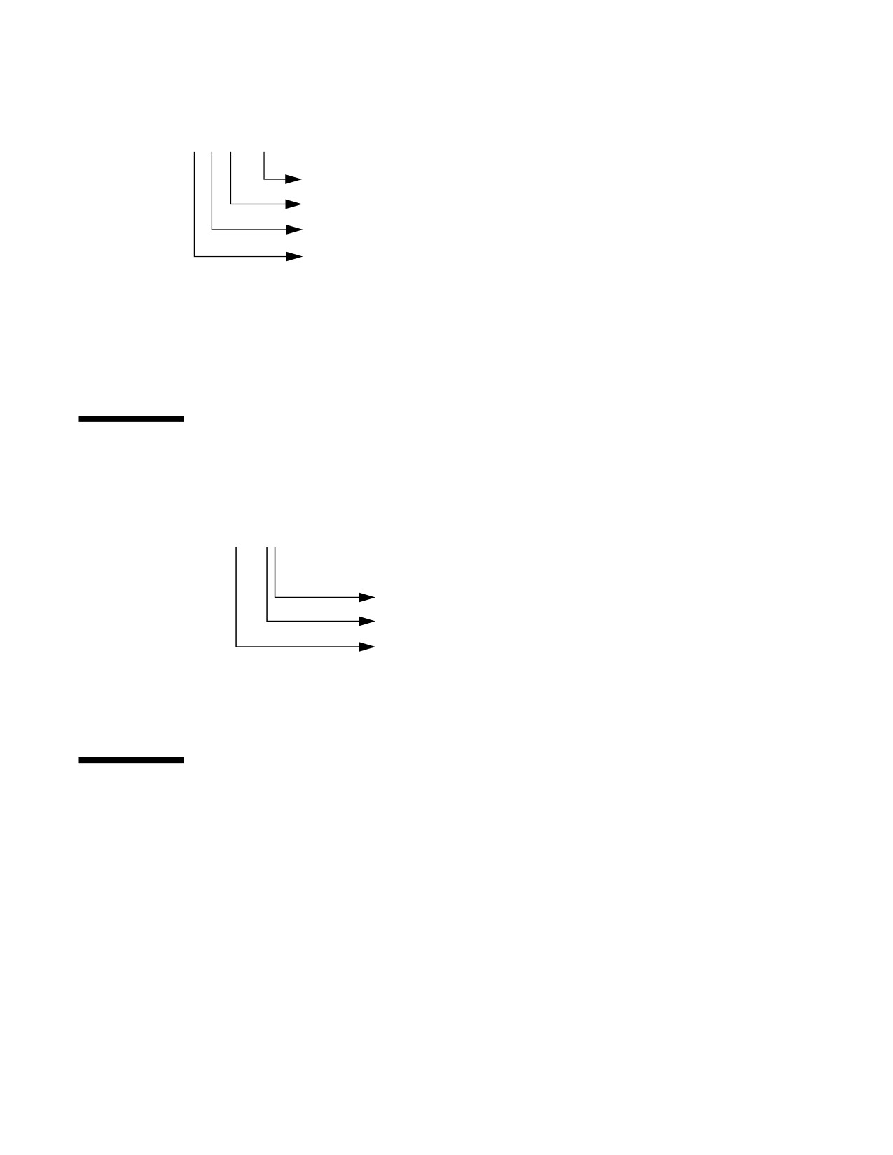
IA: Disks With SCSI Controllers
To specify a slice on a disk with a SCSI controller on an IA based system, follow the
naming convention shown in the following figure.
cvtwdx[sy,pz]
Slice Number (0 to 7) or fdisk Partition Number (0 to 4)
Drive Number
Physical Bus Target Number
Logical Controller Number
If you have only one controller on your system, v will always be 0.
For SCSI controllers, w is the target address as set by the switch on the back of the
unit, and x is the logical unit number (LUN) of the drive attached to the target. If the
disk has an embedded controller, x is usually 0.
To indicate the entire Solaris fdisk partition, specify slice 2 (s2).
Logical Tape Device Names
Logical tape device files are found in the /dev/rmt/* directory as symbolic links
from the /devices directory.
/dev/rmt/xy
Tape Density (l,m,h,c,u)
Logical Unit Number (0-n)
Raw Magnetic Tape Device
The first tape device connected to the system is 0 (/dev/rmt/0), which might be
one of the following types: QIC-11, QIC-24, QIC-150, or Exabyte. Tape density values
(l, m, h, c, and u) are described in Chapter 47.
Logical CD-ROM Device Names
The logical device name that represents the first CD-ROM device on a system is
/dev/dsk/c0t6d0s0.
316
Since CD-ROMs are managed by Volume Management, the logical CD-ROM device
name is usually not used unless you want to mount the CD manually. See Chapter
14 for information on accessing your CD-ROM device.
Accessing Devices (Overview)
317
318
CHAPTER
27
Managing Disks Topics
This section provides instructions for managing disks in the Solaris environment.
This section contains these chapters.
Provides an overview of Solaris disk slices and an
Chapter 28
introduction to the format utility.
Provides step-by-step instructions for formatting a disk,
Chapter 29
examining disk labels, and repairing a defective disk
sector.
Provides step-by-step instructions for adding a disk to a
Chapter 30
SPARC based system.
Provides step-by-step instructions for adding a disk to
Chapter 31
an IA based system.
Provides a description of the format utility’s menu and
Chapter 32
commands. This chapter also includes information about
the format.dat file, rules for providing input to
format commands, and instructions on using the help
facility.
319
320
CHAPTER
28
Disk Management (Overview)
This overview chapter provides conceptual information about Solaris disk slices and
introduces the format utility.
This is a list of the overview information in this chapter.
“Disk Terminology” on page 322
“About Disk Slices” on page 323
“SPARC: Disk Slices” on page 323
“IA: Disk Slices” on page 324
“Determining Which Slices to Use” on page 327
“The format Utility” on page 328
“Guidelines for Using the format Utility” on page 330
“Formatting a Disk” on page 331
“About Disk Labels” on page 332
“Partition Table” on page 332
For instructions on how to add a disk drive to your system, see Chapter 30 or
Chapter 31.
What’s New in Disk Management?
This section describes features introduced in the Solaris 8 release.
321
IA: Support for Large Disks
This Solaris release fully uses disks larger than 8 Gbytes because of improved BIOS
interfaces. Previously, the following limitations impacted IA based systems running
the Solaris Intel Platform Edition:
On IDE disks, only the first 8 Gbytes could be used by the system.
On either SCSI or IDE disks, only the first 8 Gbytes could only be used for the root
(/) slice.
Both of these restrictions have been removed on systems with improved BIOSes.
See Solaris
8
(Intel Platform Edition) Installation Guide for more information.
Where to Find Disk Management Tasks
Use these references to find step-by-step instructions for managing disks.
Chapter 30
Chapter 31
Introduction
Managing disks in the Solaris environment usually involves setting up the system
and running the Solaris installation program to create the appropriate disk slices and
install the operating system. Occasionally, you might need to use the format utility
to add a new disk drive or replace a defective one.
Disk Terminology
Before you can effectively use the information in this section, you should be familiar
with basic disk architecture. In particular, you should be familiar with the following
terms:
Track
Cylinder
Sector
Disk controller
322

Disk label
Device drivers
If you are unfamiliar with these terms, refer to the glossary (for a brief definition) or
product information from the disk’s manufacturer.
About Disk Slices
Files stored on a disk are contained in file systems. Each file system on a disk is
assigned to a slice—a group of cylinders set aside for use by that file system. Each
disk slice appears to the operating system (and to the system administrator) as
though it were a separate disk drive.
See Chapter 34 for information about file systems.
Note - Slices are sometimes referred to as partitions. This book uses slice but certain
interfaces, such as the format utility, refer to slices as partitions.
When setting up slices, remember these rules:
Each disk slice holds only one file system.
No file system can span multiple slices.
Slices are set up slightly differently on SPARC and IA platforms. The table below
summarizes the differences:
TABLE 28-1
Slice Differences on Platforms
SPARC Platforms
IA Platforms
Whole disk is devoted to Solaris environment Disk is divided into fdisk partitions, one
per operating environment
Disk is divided into eight slices, numbered
The Solaris fdisk partition is divided into
0-7
10 slices, numbered 0-9
SPARC: Disk Slices
On SPARC based systems, Solaris defines eight disk slices and assigns to each a
conventional use. These slices are numbered 0 through 7. The table below
summarizes the contents of the eight Solaris slices on a SPARC based system.
Disk Management (Overview)
323
TABLE 28-2
SPARC: Customary Disk Slices
Usually Found on
Client or Server
Slice
File System
Systems?
Purpose
0
root
Both
Holds files and directories that make up
the operating system.
1
swap
Both
Provides virtual memory, or swap space.
Swap space is used when running
programs are too large to fit in a
computer’s memory. The Solaris operating
environment then “swaps” programs from
memory to the disk and back as needed.
2
—
both
Refers to the entire disk, by convention. It
is defined automatically by the format
and the Solaris installation programs. The
size of this slice should not be changed.
3
/export
Server only
Holds alternative versions of the operating
system. These alternative versions are
required by client systems whose
architectures differ from that of the server.
Clients with the same architecture type as
the server obtain executables from the /
usr file system, usually slice 6.
4
/export/
Server only
Provides virtual memory space for client
swap
systems.
5
/opt
Both
Holds application software added to a
system. If a slice is not allocated for this
file system during installation, the /opt
directory is put in slice 0.
6
/usr
Both
Holds operating system commands—also
known as executables— designed to be run
by users. This slice also holds
documentation, system programs (init
and syslogd, for example) and library
routines.
7
/home or
Both
Holds files created by users.
/export/
home
324
IA: Disk Slices
On IA based systems, disks are divided into fdisk partitions. An fdisk partition is
a section of the disk reserved for a particular operating environment, such as Solaris.
Solaris places ten slices, numbered 0-9, on a Solaris fdisk partition as shown in the
following table.
TABLE 28-3
IA: Customary Disk Slices
Usually Found on
Client or Server
Slice
File System
Systems?
Purpose
0
root
Both
Holds the files and directories that
make up the operating system.
1
swap
Both
Provides virtual memory, or swap
space. Swap space is used when
running programs are too large to
fit in a computer’s memory. The
Solaris operating environment
then “swaps” programs from
memory to the disk and back as
needed.
2
—
Both
Refers to the entire disk, by
convention. It is defined
automatically by the format
utility and the Solaris installation
programs. The size of this slice
should not be changed.
3
/export
Server only
Holds alternative versions of the
operating system. These
alternative versions are required
by client systems whose
architectures differ from that of
the server.
4
/export/swap
Server only
Provides virtual memory space
for the client systems.
5
/opt
Both
Holds application software added
to a system. If a slice is not
allocated for this file system
during installation, the /opt
directory is put in slice 0.
Disk Management (Overview)
325
TABLE 28-3 IA: Customary Disk Slices
(continued)
Usually Found on
Client or Server
Slice
File System
Systems?
Purpose
6
/usr
Both
Holds operating system
commands—also known as
executables—that are run by users.
This slice also holds
documentation, system programs
(init and syslogd, for
example) and library routines.
7
/home or /
Both
Holds files created by users.
export/home
8
—
Both
Contains information necessary
for Solaris to boot from the hard
disk. It resides at the beginning of
the Solaris partition (although the
slice number itself does not
indicate this), and is known as the
boot slice.
9
—
Both
Provides an area reserved for
alternate disk blocks. Slice 9 is
known as the alternate sector
slice.
Using Raw Data Slices
The SunOS operating system stores the disk label in block 0, cylinder 0 of each disk.
This means that using third-party database applications that create raw data slices
must not start at block 0, cylinder 0, or the disk label will be overwritten and the
data on the disk will be inaccessible.
Do not use the following areas of the disk for raw data slices, which are sometimes
created by third-party database applications:
1. Block 0, cylinder 0, where the disk label is stored.
2. Avoid cylinder 0 entirely for improved performance.
3. Slice 2, which represents the entire disk.
326
Slice Arrangements on Multiple Disks
Although a single disk that is large enough can hold all slices and their
corresponding file systems, two or more disks are often used to hold a system’s
slices and file systems.
Note - A slice cannot be split between two or more disks. However, multiple swap
slices on separate disks are allowed.
For instance, a single disk might hold the root (/) file system, a swap area, and the
/usr file system, while a separate disk is provided for the /export/home file
system and other file systems containing user data.
In a multiple disk arrangement, the disk containing the operating system software
and swap space (that is, the disk holding the root (/) or /usr file systems or the
slice for swap space) is called the system disk. Disks other than the system disk are
called secondary disks or non-system disks.
Locating a system’s file systems on multiple disks allows you to modify file systems
and slices on the secondary disks without having to shut down the system or reload
operating system software.
Having more than one disk also increases input-output (I/O) volume. By distributing
disk load across multiple disks, you can avoid I/O bottlenecks.
Determining Which Slices to Use
When you set up a disk’s file systems, you choose not only the size of each slice, but
also which slices to use. Your decisions about these matters depend on the
configuration of the system to which the disk is attached and the software you want
to install on the disk.
The system configurations are:
Servers
Standalone systems
Each system configuration requires the use of different slices. The table below lists
these requirements.
Disk Management (Overview)
327

TABLE 28-4
System Configurations and Slice Requirements
Standalone
Slice
Servers
Systems
0
root
root
1
swap
swap
2
—
—
3
/export
—
4
—
/export/swap
5
/opt
/opt
6
/usr
/usr
7
/export/home
/home
See “Overview of System Types” on page 96 for more information about system
configurations.
Note - The Solaris installation program provides slice size recommendations based
on the software you select for installation.
The format Utility
Read the following information if you want to see a conceptual view of the format
utility and it uses before proceeding to the “how-to” or reference sections.
Definition
The format utility is a system administration tool used to prepare hard disk drives
for use on your Solaris system. The format utility cannot be used on diskette drives,
CD-ROM drives, or tape drives.
328
Features and Benefits
The table below shows the features and associated benefits that the format utility
provides.
TABLE 28-5
Features and Benefits of the format Utility
Feature
Benefit
Searches your system for all
Reports:
attached disk drives
Target location
Disk geometry
Whether the disk is formatted
If the disk has mounted partitions
Retrieves disk labels
Used in repair operations
Repairs defective sectors
Allows administrators to repair disk drives with recoverable
errors instead of sending the drive back to the manufacturer
Formats and analyzes a disk Creates sectors on the disk and verifies each sector
Partitions a disk
Divides a disk so individual file systems can be created on
separate slices
Labels a disk
Writes disk name and configuration information to the disk
for future retrieval (usually for repair operations)
All of the options of the format utility are fully described in Chapter 32.
When to Use the format Utility
Disk drives are partitioned and labeled by the Solaris installation program as part of
installing the Solaris release. You might need to use the format utility when:
Displaying slice information
Dividing a disk into slices
Adding a disk drive to an existing system
Formatting a disk drive
Repairing a disk drive
Disk Management (Overview)
329
The main reason a system administrator uses the format utility is to divide a disk
into disk slices. These steps are covered in Chapter 30 and Chapter 31.
See the section below for guidelines on using the format utility.
Guidelines for Using the format Utility
TABLE 28-6
The format Utility Guidelines
Use format To
Considerations ...
Where to Go ...
Format a disk
Any existing data will be destroyed
“How to Format a Disk”
when a disk is reformatted.
on page 342
The need for formatting a disk drive has
dropped as more and more
manufacturers ship their disk drives
formatted and partitioned. You might not
need to use the format utility when
adding a disk drive to an existing
system.
If a disk has been relocated and is
displaying a lot of disk errors, you can
attempt to reformat it, which will
automatically remap any bad sectors.
Replace a
Data from the damaged system disk
must be restored from a backup medium;
Chapter 30 or Chapter 31
system disk
or if the system must be
otherwise the system will have to be
reinstalled by using the installation
reinstalled, Solaris
8
program.
Advanced Installation
Guide
Divide a disk
Any existing data will be destroyed
Chapter 30 or Chapter 31
into slices
when a disk with existing slices is
repartitioned and relabeled.
Existing data must be copied to backup
media before the disk is repartitioned
and restored after the disk is relabeled.
330
TABLE 28-6
The format Utility Guidelines
(continued)
Use format To
Considerations ...
Where to Go ...
Add a
Any existing data must be restored from
Chapter 30 or Chapter 31
secondary disk
backup media if the secondary disk is
to an existing
reformatted or repartitioned.
system
Some customer sites prefer to replace
Repair a disk
rather than repair defective drives. If
Chapter 32
drive
your site has a repair contract with the
disk drive manufacturer, you might not
need to use the format utility to repair
disk drives.
Repairing a disk drive usually means
that a bad sector is added to a defect list.
New controllers remap bad sectors
automatically with no system
interruption.
If the system has an older controller, you
might need to remap a bad sector and
restore any lost data.
Formatting a Disk
In most cases, disks are formatted by the manufacturer or reseller and do not need to
be reformatted when you install the drive. To determine whether or not a disk is
formatted, use the format utility. See “How to Determine if a Disk is Formatted” on
page 341 for more information.
If you determine that a disk is not formatted, use the format utility to format the
disk.
Formatting a disk accomplishes two steps:
Preparing disk media for use
Compiling a list of disk defects based on a surface analysis
Caution - Formatting is a destructive process—it overwrites data on the disk. For
this reason, disks are usually formatted only by the manufacturer or reseller. If you
think disk defects are causing recurring problems, you can use the format utility to
do a surface analysis, but be careful to use only the commands that do not destroy
data. See “How to Format a Disk” on page 342 for details.
Disk Management (Overview)
331