ABB Freelance Getting Started (Version 9.2 SP1) - page 4
FTP Server under Windows 7
Section 2 Freelance Installation
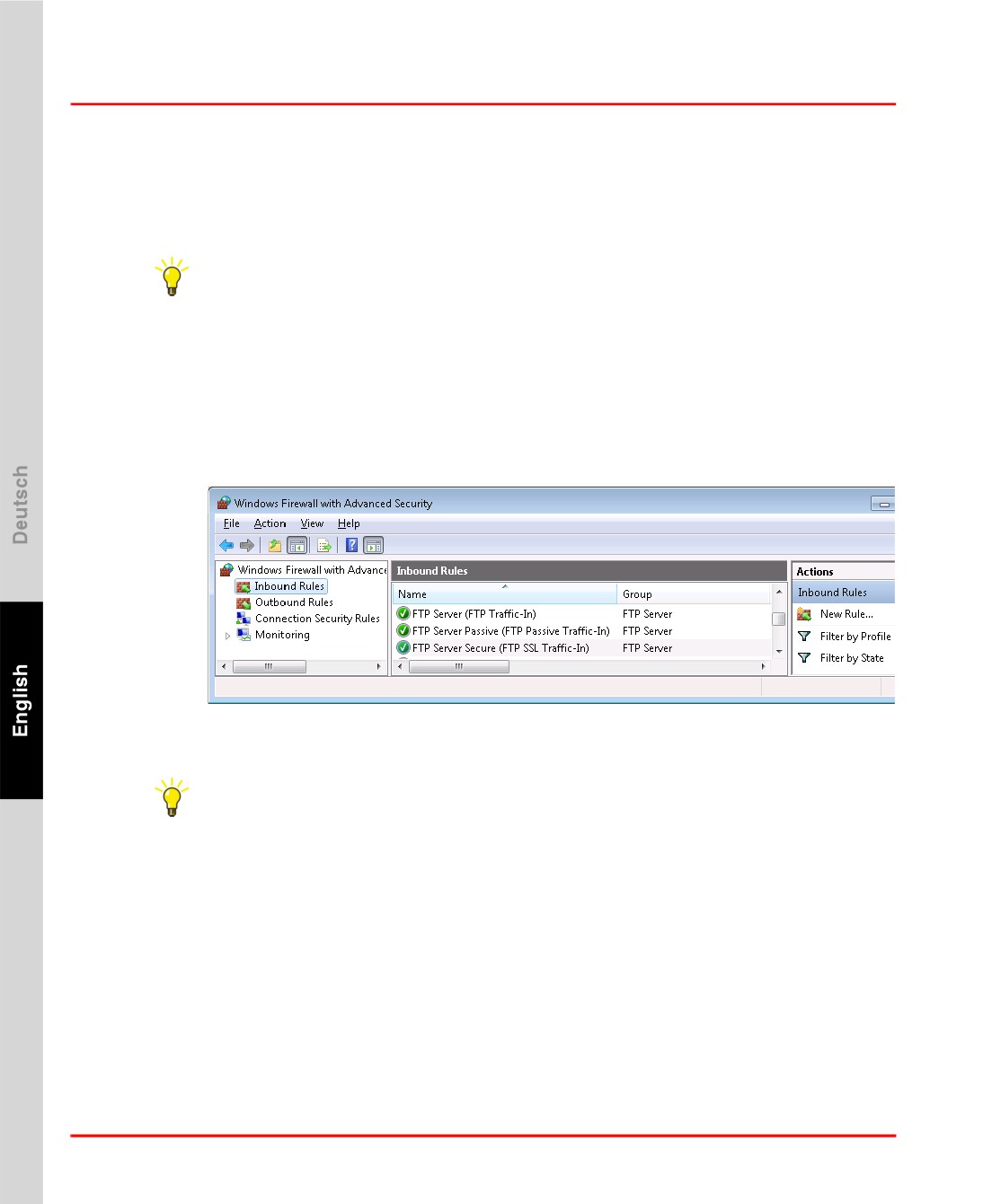
installer has added 5 preconfigured firewall rules, 3 inbound and 2 outbound, which
need to be enabled.
Open the configuration dialog of the Windows Firewall with Advanced Security.
> Start > Control Panel > Administrative Tools > Windows Firewall with
Advanced Security
> Select Inbound Rules
Enable the following inbound rules:
1.
FTP Server(FTP-In)
2.
FTP Server Passive(FTP Passive Traffic-In)
3.
FTP ServerSecure(FTP SSL Traffic-In)
FTP Inbound FTP Rules Windows 7.bmp
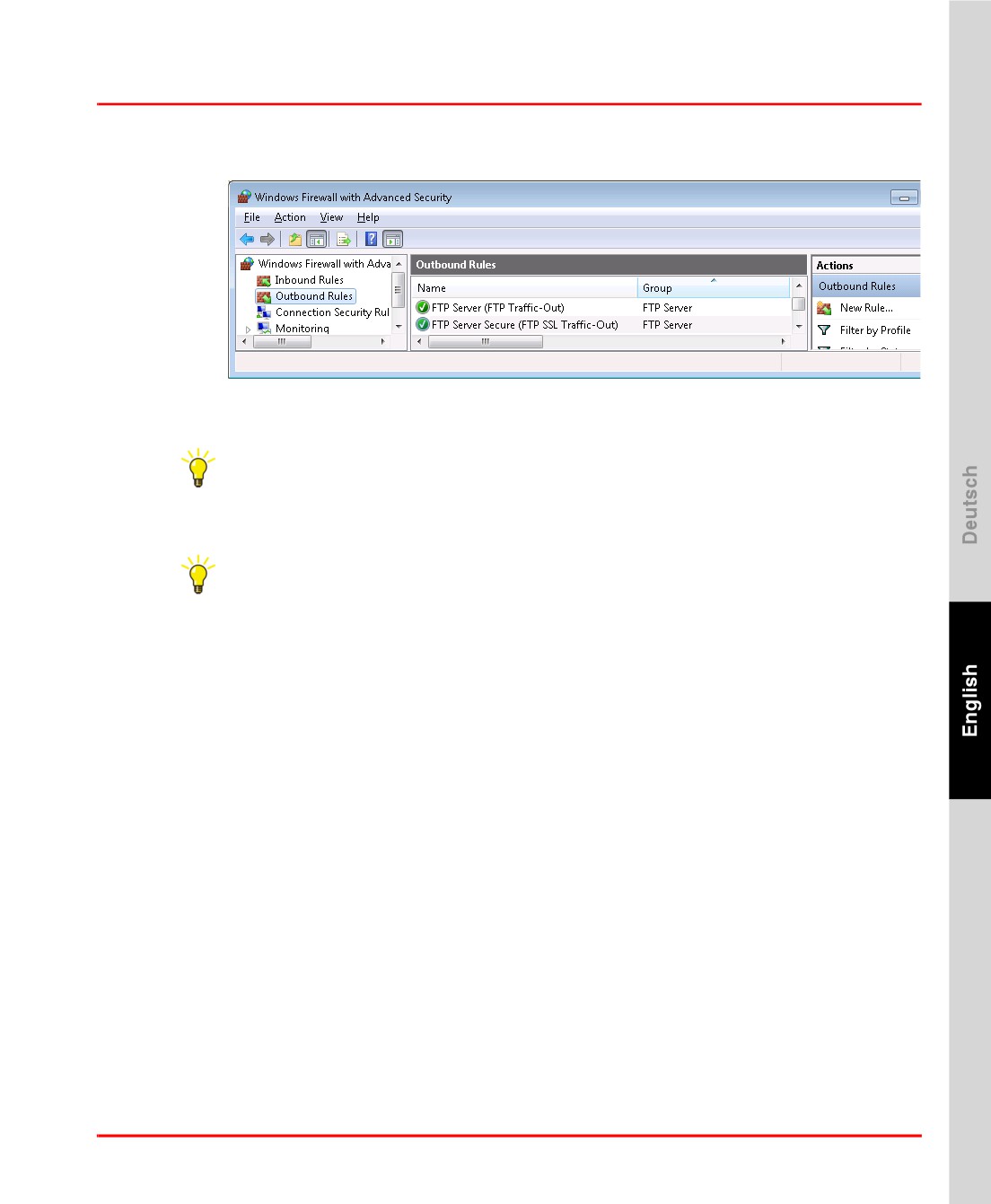
> Select Outbound Rules
Enable the follwoing outbound rules:
1.
FTP server(FTP Traffic-Out)
2.
FTP Server Secure(FTP SSL Traffic-Out)
94
Section 2 Freelance Installation
Testing the FTP Server
FTP Outbound FTP Rules Windows 7.bmp
If the FTP server is initially installed, the firewall still blocks the traffic until the
service of the FTP server is restarted.
Restart the Windows service Microsoft FTP Service:
> Start > Control Panel > System and Security > Administrative Tools
> Double-click Services
> Select Microsoft FTP Service
> Click Restart the Service
The FTP server is now restarted and the firewall will use the exception rules now.
Testing the FTP Server
To test the FTP server functionality:
Logon with an FTP client (e.g. the Windows ftp command line client or FileZilla),
from another windows PC using the created limited user (e.g. “FreelancerFTP”) for
login.
Upload a file.
Download a file.
Now the FTP based functionality in Control Builder F and DigiVis can be
configured and used.
95
Java Installation
Section 2 Freelance Installation
Java Installation
Java is used to display Applets in a Web-Browser. It is necessary, if the following
advanced functionality is needed:
•
Using the Telnet-Applet in the controller web interface (e.g. AC800F)
•
Using the Java GUI of the controller emulator
Preconditions
Internet Explorer 8
Installation
Java 6 Update 20 or higher is recommended.
Download the Java Runtime Environment (JRE) from the website, www.java.com
and install it.
Test Java
To Test the Java installation one can utilize the controller emulator. Start the Internet
Explorer and open the Controller Emulator Manager. If the controller emulator is
running on the local machine it can be found at http://localhost:8888.
Start a controller emulator station and click the GUI Window of the station to view
the Java GUI.
Accessing the controller emulator manager or the web interface of a process
station may fail, if an internet proxy is configured.
To exclude specific IP addresses from being accessed via the proxy;
Start the Internet Explorer
> Tools > Internet Options > Connections > LAN settings
Press the Advanced button.
Enter the IP addresses or IP address patterns that shall not be accessed via an
internet proxy.
96
Section 3 Initial Steps
General Notes
Once you have carried out the installation of Control Builder F as described in the
preceding section, you can immediately begin to set up a project.
Use the Start menu to launch Control Builder F.
If your hard key is not attached, or if you have not installed a license file, a message
will be displayed to that effect. Correct the cause of the problem and relaunch the
program.
The version details of the installed software are displayed in the “About Control
Builder F” window. Confirm this dialog using the OK button.
Creating a Project File
Choose New from the Project menu and specify a file name for saving your project
on the hard disk. The default directory used is <Freelance_Installation_Directory
>\proj, but you may choose a different directory if you wish.
Once you have specified a unique file name a further dialog appears, allowing you
to enter general project data such as project number, person in charge, customer etc.
This data can also be entered or modified at any time in the future. When this dialog
is confirmed with the OK button an empty project file is created.
The first step of the configuration process involves setting up the software view for
the project. This means that tags, variables and the functions to be calculated are
defined.
In a second step this configuration is assigned to the existing hardware, that is the
process stations and I/O units.
97
Step 1: Configuring the Software View of the Project
Section 3 Initial Steps
Step 1: Configuring the Software View of the Project
Once you have defined the general project data you can choose the Configuration!
menu or use the corresponding tool bar button to reach the software view of the
configuration, the project tree.
The project tree displays the functions of a project in a clear format. The individual
elements or objects, generally known as project elements, are structured in
accordance with IEC 61131-3. To develop a project tree, select a node in the tree
and choose Insert next level / Insert below or Insert above from the menu, or use
the insertion options directly from the context menu. According to which node is
selected in the project tree, you will be presented with a list of objects which can be
inserted at that position in the tree.
The uppermost element in a project is the Configuration CONF, which is the sum
total of all the project elements in a Freelance system.
The first structural level below the configuration is formed by the resources, which
represent the various different stations in a project. For the processing of the process
itself there are the D-PS (process station) resources, for operation and observation
of the process there are the D-OS (operator station) resources, for interfacing to
external systems there are the D-GS (gateway station) resources, and for
integrating data from external systems there is the OPC-S (OPC server) resource.
Insert a process station below the configuration node. One can choose between a
redundant (D-PS/RED) or non-redundant (D-PS) process station to add. Further
specification, e.g. whether a rack-based station or an AC 800F is used, is performed
later in the hardware structure.
Insert a D-PS process station now and name it “PS”.
Once a name has been assigned to the resource, its basic structure is added to the
project tree. Below the resource node, system functions and user-defined functions
are organized in the two task lists <Res-Name>.SYSTask and <Res-
Name>.USRTask.
Configuration of the system task provides an opportunity to define the response of
the process station to specific situations such as cold start, warm start and
redundancy transfer.
98
Section 3 Initial Steps
Step 1: Configuring the Software View of the Project
Below the node USRTask the user defined functions are specified which are to be
executed in the process station. These functions can be executed in different tasks. A
task is represented as a separate node in the project tree.
A Default Task can be set up. This task is always executed when none of the other
tasks is being calculated. Besides the Default Tasks other tasks can be created.
Typically each task is processed repeatedly in Interval Mode with a configured
time interval -the task Cycle time.
Now create a Task.
PL programs (program lists) and SFC programs (sequential function chart
programs) are specified below each task. The actual functions in programs are
configured below a program list.
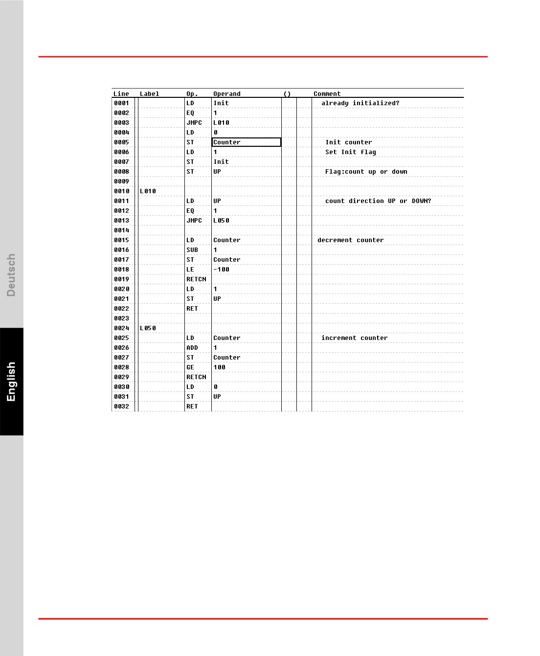
Create a program list with an IL (instruction list) program below it. For example,
enter the following program (creation of a saw-tooth curve):
99
Step 1: Configuring the Software View of the Project
Section 3 Initial Steps
first01us.bmp
While you are entering data you will prompted to define the variables being used.
You should define the variables Init and UP with data type BOOL, and Counter
with data type INT.
To check the program choose IL program > Check from the menu. Any errors that
may be detected are shown in a list. Double-clicking on an error message will take
you automatically to the place where the error has been detected. Correct the
error(s) and run the plausibility check again.
Clicking Back will return you to the project tree. Another program should now be
used to monitor the current count and generate an alarm message if required.
100
Section 3 Initial Steps
Step 1: Configuring the Software View of the Project
Add another FBD (function block diagram) program below the IL program. Double-
click on the program or click on Edit to move to the FBD editor.
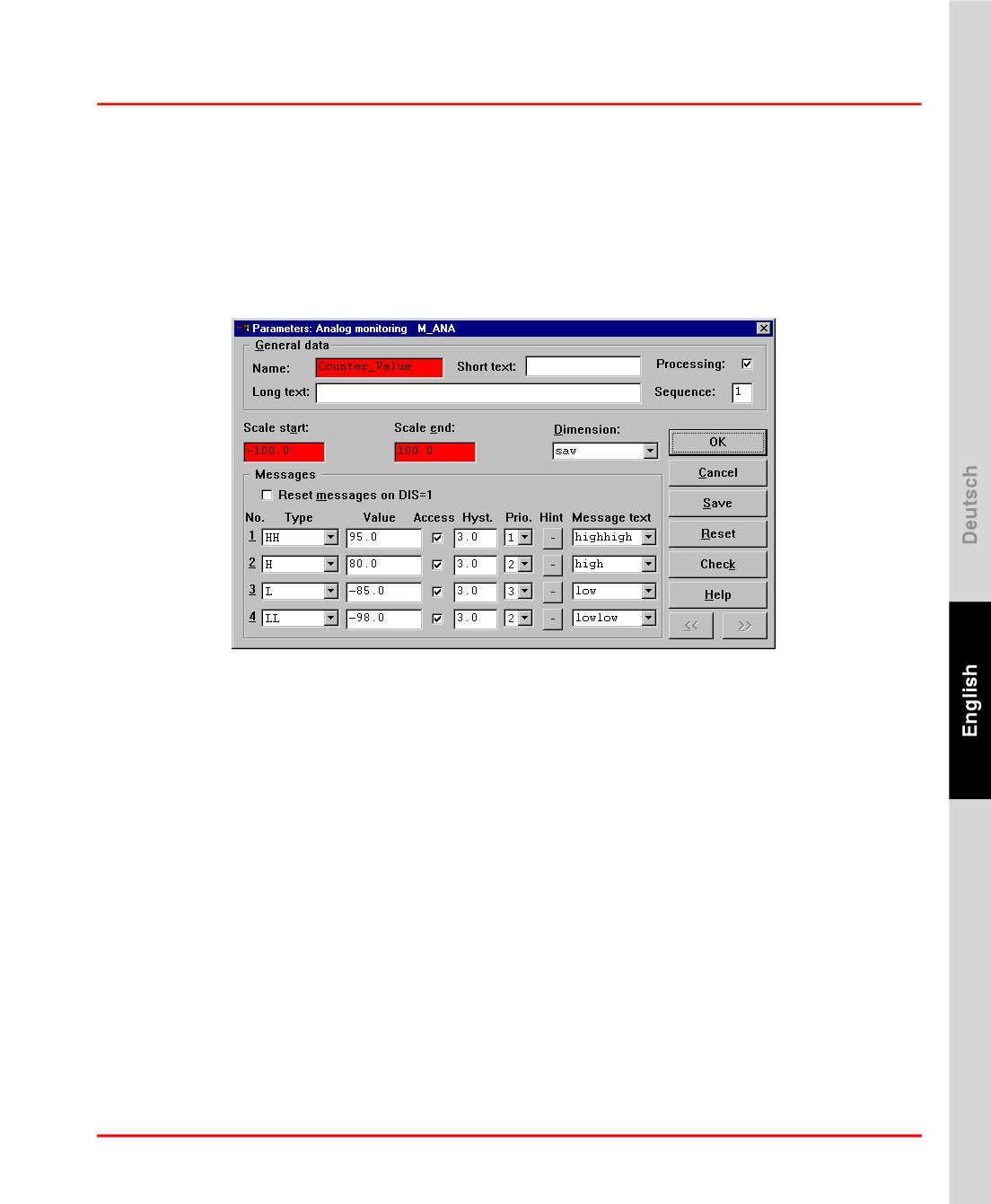
Select an analog monitoring function block M_ANA from the Function Blocks
menu and define Parameters for it by specifying a name, setting the scaling from -
100.0 to 100.0 (in accordance with the counter in the IL program), and define up
to 4 limit values. Example of a completed parameter mask:
first02us.bmp
Place a variable in the FBD sheet. To do so, choose FBD elements > Variable read
from the menu (the variable Counter should be read and linked with the input IN of
the monitoring block). You can enter the variable name directly in the parameter
mask, or use the F2 key to choose it from a list. Before linking the variable Counter
with the function block’s input pin IN, its data type must first be converted from
integer to REAL. This is done by choosing the converter block TO_RE (to REAL)
from the menu: Blocks > Converter > Data type to REAL.
Draw a line from the variable to the converter’s input and from the converter’s
output to the function block’s input IN: Context menu > Draw lines.
The processing sequence is shown in the lower right corner of the function blocks. It
is not correct and needs to be adjusted. Open the parameter mask for the analog
monitoring block (Right click > Parameters...) and change the sequence from
1 to 2. The processing sequence for the converter block will be automatically
adjusted to 1.
101
Step 2: Configuring the Hardware Assignment
Section 3 Initial Steps
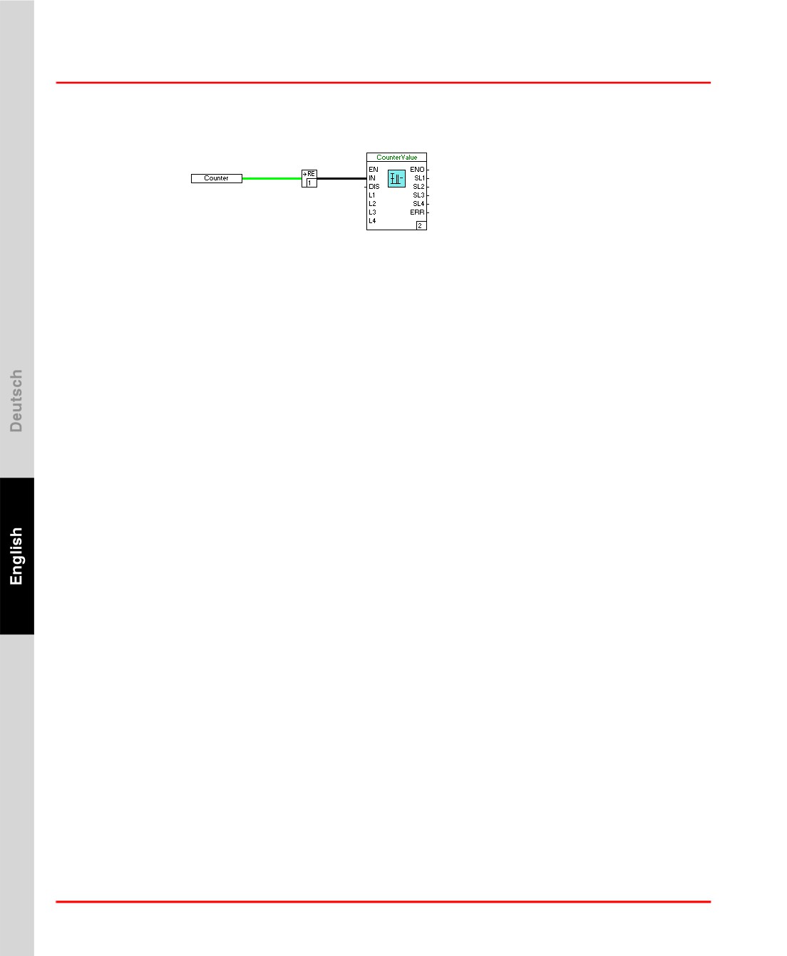
Your program could then look something like this:
first03us.bmp
Choose FBD program > Check from the menu to validate the plausibility of the
program.
Now Save the program and Exit the FBD editor. After exiting the FBD editor you
will return to the project tree view.
Now check the plausibility of the project tree. Selecte the top most node and click
Project > Check All.
Any errors that may be detected are shown in a list. Double-clicking on an error
message will take you automatically to the place where the error has been detected.
Correct the errors and check the project for plausibility again.
Step 2: Configuring the Hardware Assignment
To configure the hardware in the project, choose Hardware structure from the
System menu or click the relevant button on the tool bar.
The hardware editor shows two representations of the hardware in the project. In the
left-hand section of the screen all the hardware is represented in a tree view, while
the right-hand section contains a graphical view of the currently-selected object.
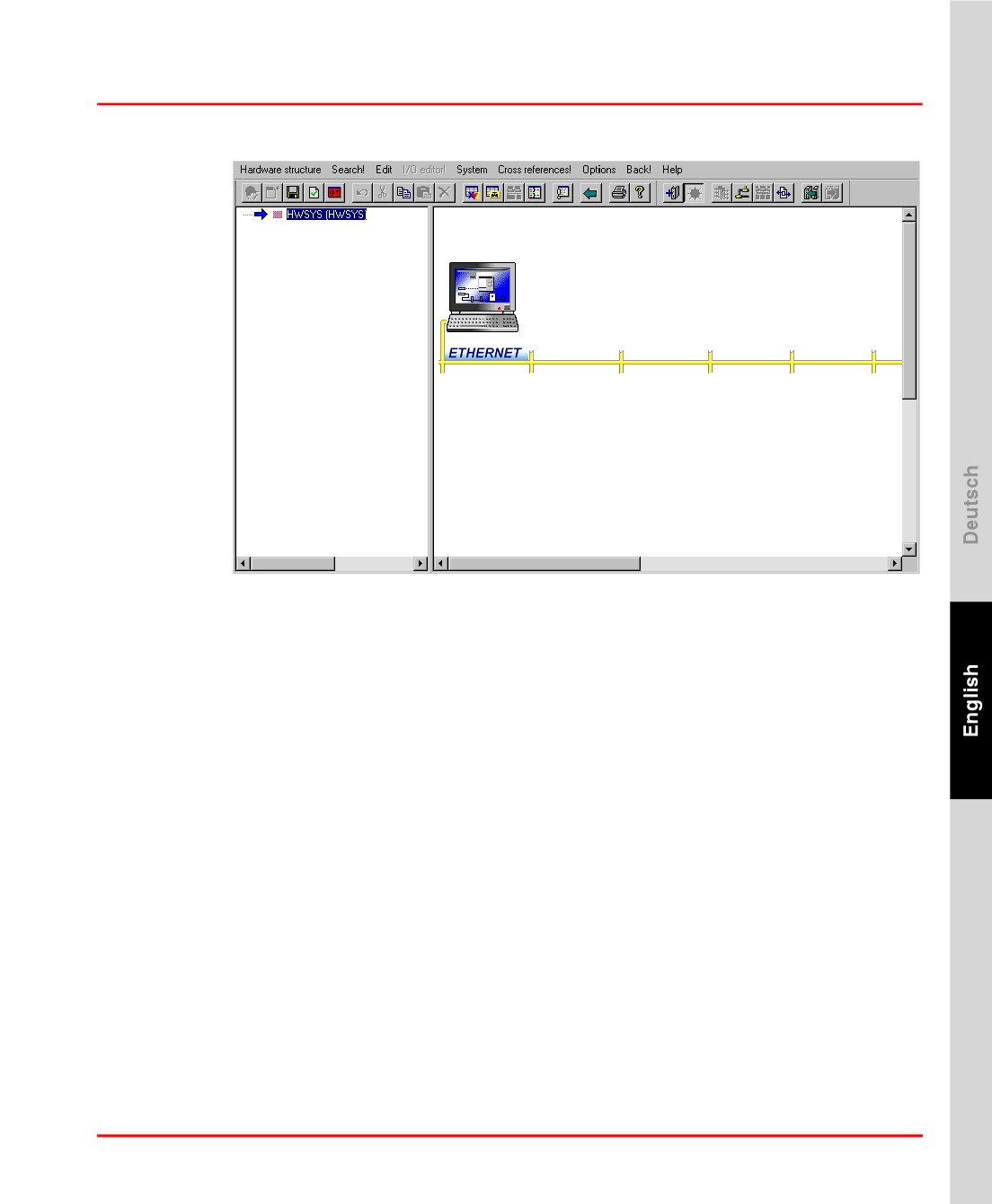
A project with no hardware configuration is displayed as follows:
102
Section 3 Initial Steps
Step 2: Configuring the Hardware Assignment
first10us.bmp
The computer displayed represents the configuration PC (Control Builder F), and
cannot be modified. The yellow line represents the system bus. Portrayed below the
system bus are the process stations, while above the bus - adjacent to the
configuration PC - are the configured operator- and gateway stations.
The project hardware is configured as follows:
•
Select object in the tree structure and choose Insert... from the Edit menu
or
•
Select object in the tree structure and choose Insert... from the context menu
or
•
Click on an unoccupied position in the graphic view (your selection will be
indicated by a dashed red border) and double-click the left mouse button.
The following dialog presents a list of objects which can be inserted at the selected
position.
Now insert a process station in accordance with the available hardware.
103
Step 3: Commissioning
Section 3 Initial Steps
The hardware and software components of the project are integrated by selecting the
hardware and the choose Resource allocation... from the Edit menu to assign a
resource.
Now select the process station and assign the “PS” resource from the project tree.
The network configuration dialog (Menu: Hardware structure > Network) allows
the stations’ resource ID and IP address to be defined. Select the process station and
click Edit. Enter a unique resource ID for your station and its IP address. Close the
network configuration with OK.
Usually no changes to the default boot parameters of the process station are
necessary. If you need to edit them nevertheless, select the process station in the
hardware manager. Then select Edit > Parameters
The Boot Parameters of a
process station can now be modified. Close the hardware parameters dialog.
To validate the plausibility of the hardware configuration select Hardware
structure > Check all. No errors should be shown in the Plausibility check error
list.
Now save the changes with Hardware structure > Save and exit the hardware
manager with Hardware structure > Exit.
Select the uppermost node in the project tree and check the plausibility of all project
data. When the Project > Check all menu item is chosen, all objects below the
selected node are checked. The menu item Project > Check leads to only those
objects being checked which are displayed with a pink node.
Step 3: Commissioning
Once any errors that the plausibility check reported have been rectified, the project
can be commissioned. Choose Project > Commissioning to switch from
configuration to commissioning mode.
When switching to commissioning mode, Control Builder F attempts to establish a
communication link with all the configured stations. As well as the resource nodes,
the current states of the connections are indicated in the project tree.
In a newly-installed system the boot EPROM will have been loaded into the process
station in the course of the installation process. If the IP addresses and subnet masks
104
Section 3 Initial Steps
Step 4: Testing the Configuration
have been configured correctly, then the project tree node for the process station will
be labeled “No operating system”. Other states include:
•
“Running”: Operating system or configuration has been loaded.
•
“Version error”: The configuration in the process station belongs to another
project or is outdated.
•
“Wrong DMS version”: The version of communication software in the
process station is different from the Control Builder F version. With the
configuration tool “Configure”, the current boot EPROM must be loaded into
the process station first.
An arrow before the node indicates that the data for the node is not yet available on
the associated hardware and still needs to be loaded.
Select the resource node of the process station and open the context menu. If
commissioning for the first time, choose Load > Whole station. Changes and
enhancements to the configuration can be loaded into the process station
retrospectively with Load > Changed objects.
If the load operation has concluded successfully, the nodes in the project tree will
appear green and the load arrows will be removed.
Step 4: Testing the Configuration
In commissioning mode there are various different options in Control Builder F for
testing and checking the current project configuration. Select an object and double-
click on it to open it. As in the configuration phase, the relevant editor is then
opened. It is not possible to modify the configuration here, but the current values
can be checked and to a certain extent influenced.
IL Program
If an IL program has been loaded into a process station and executed there, then the
IL editor can be opened in Control Builder F commissioning mode. For each step in
the calculation, the current values for variables are displayed before the comment
column. Boolean variables are displayed as F for FALSE and T for TRUE.
105
Step 5: Saving the Project Data
Section 3 Initial Steps
FBD Program
If an FBD program has been loaded into a process station and executed there, then
the FBD editor can be opened in Control Builder F commissioning mode. The
current value can be read from the connecting lines.
Lines for data of type BOOL are solid for the value TRUE and dashed for the value
FALSE.
The cursor can be moved to all other lines. The current value is shown in the form of
a data tip.
The current values for a function block pin are shown when the cursor is moved to
it.
Value Window
The value window can be used to provide a lasting display of a value. Another
window is displayed. Choose Windows > Show value window to open the value
window.
Once a variable, a data flow line or a function block pin has been selected in an
editor or a list, Enter variable... can be chosen from the context menu or the
Windows menu. The format for displaying the value is chosen in another dialog.
After this dialog has been confirmed, the variable will appear in the value window.
The value displayed is updated once per second.
Step 5: Saving the Project Data
The Control Builder F project data can be saved in the binary format (Control
Builder F project file, PRO) or as text file (comma separated values, CSV). The
standard format is binary. For data exchange purposes projects can be exported as
csv-text file.
To save a project:
•
In the project overview: Project > Save
•
In the project tree: Project > Save
To export a project:
106
Section 3 Initial Steps
Step 6: Configuring an Operator Station
•
In the project overview: Project > Export...
A file name for the csv file must be entered then.
Archived and exported projects provide additional data safety and recovery options.
Export files are needed for the product upgrade procedure.
Step 6: Configuring an Operator Station
The DigiVis software must be installed on a computer connected to the Control
Builder F through a network. The DigiVis software can also be installed along with
the Control Builder F software on the same PC.
To create an operator station in Control Builder F, switch back to configuration
mode and to the project tree view. Select the process station node. Choose Edit >
Insert below to display the list of possible resource types. Choose Operator
station D-OS and specify a name.
Move to the hardware structure and select the uppermost node in the tree. Choose
Edit > Insert to display the list of possible resource types. Choose VIS Operator
station and click OK. Specify a name and the mounting position for the new
hardware. The predefined values can be accepted with the OK button.
Select the new resource in the tree or in the graphic view, then choose Edit >
Resource allocation
Select the software resource that you defined previously and
assign it to the hardware.
As with the process station, the IP address or host name and the resource ID must be
configured for the operator station. In the Hardware structure > Network dialog
enter the IP address or hostname and the resource ID you defined when installing
the DigiVis software. Click OK to apply you changes.
Check the hardware plausibility by selecting the topmost hardware node and then
Hardware structure > Check.
Save your changes and exit the hardware manager. Back in the project tree view
select the uppermost node in the project tree and check the plausibility of the project
data with Project > Check.
107
Step 7: Commissioning the Operator Station
Section 3 Initial Steps
Step 7: Commissioning the Operator Station
Once any errors that the plausibility check reported have been rectified, the project
can be commissioned. Choose Project > Commissioning to switch from
configuration to commissioning mode.
As well as the resource nodes, the current states of the connections are indicated in
the project tree. If not already done, start DigiVis now on the operator station PC.
The process station should be flagged with the connection status running, and the
operator station with Version error. If the DigiVis software is running or not
reachable via the network, then No connection will be reported for the operator
station.
Select the node for the process station and choose Load > Changed objects; then
select the node for the operator station and choose Load > Whole station.
Switch to running DigiVis on the operator station. Choose Display > Faceplates.
The Tag-List is displayed. The name of the M_ANA function block is displayed in a
list. Select the name of the function block to display its faceplate.
In the M_ANA faceplate the increasing and decreasing value (saw tooth) is
visualized with a green bar. Alarms are listed in the Message list! along with their
current time stamps, when the value reaches the defined limits.
You have mastered the first steps with Freelance. You have learned how how to
write a simple program, run it on a process station, visualize its state and display
alarms. Congratulations.
Step 8: Working with Tag Types and OPC Items
This step is only for those users who would like to create and use Tag Types with
OPC Items in their projects.
Tag Type Library
(1) Create a TagType_Lib (TAG-LIB) Node in the Project Tree under CONF.
108
Section 3 Initial Steps
Step 8: Working with Tag Types and OPC Items
(2) Import the example Tag Type Library.
Edit > Import Block
Browse the file C:\Program Files\ABB Industrial
IT\Freelance\export\FreelanceSampleTagTypeLib_V1.0.prt
Click Open
The Tag_Type_Li00 Library gets added under the Pool node in the project tree.
Drag and drop it under the CONF node in the project tree below the TagType_Lib
node. The library may now be used in the project
Alternatively
Create your own tag type library.
If not already done, install the OPC Tunnel on the PC where OPC server is
installed. Select the OPC Tunnel Server option in the “Workplace type” screen
while running the Freelance installation.
OPC Tunnel Configuration
•
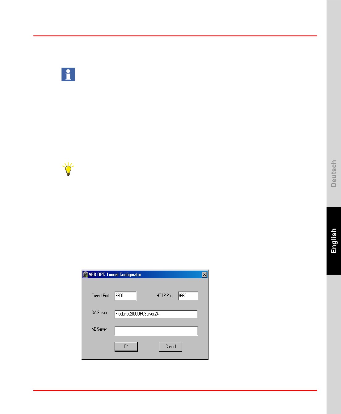
Select the OPC tunnel configurator.
•
Specify the PROG IDs of DA/AE servers and the port number of the service.
The default values are as shown below.
•
User may use the default settings or change them as required.
•
The last two characters of the PROG ID represents the unique resource ID
assigned to the OPC server.
OPC Tunnel_configurator.bmp
109
Step 8: Working with Tag Types and OPC Items
Section 3 Initial Steps
OPC Server Configuration in CBF
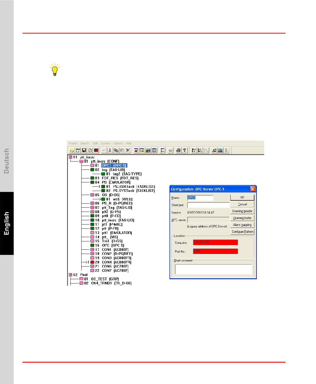
Project tree > Right-click on CONF (CONF) > Insert next level > Select OPC
Server OPC-S > Click OK.
Configuration dialog is displayed.
Enter Name (Eg. OPC1), Location, where OPC server is running.
Double-click the OPCS node
Specify the IP address of the PC on which the OPC Tunnel is installed. The port
number is the same as the one used for the OPC tunnel configuration (9950).
OPC_First_Steps_OPC_Config.bmp
110
Section 3 Initial Steps
Step 8: Working with Tag Types and OPC Items
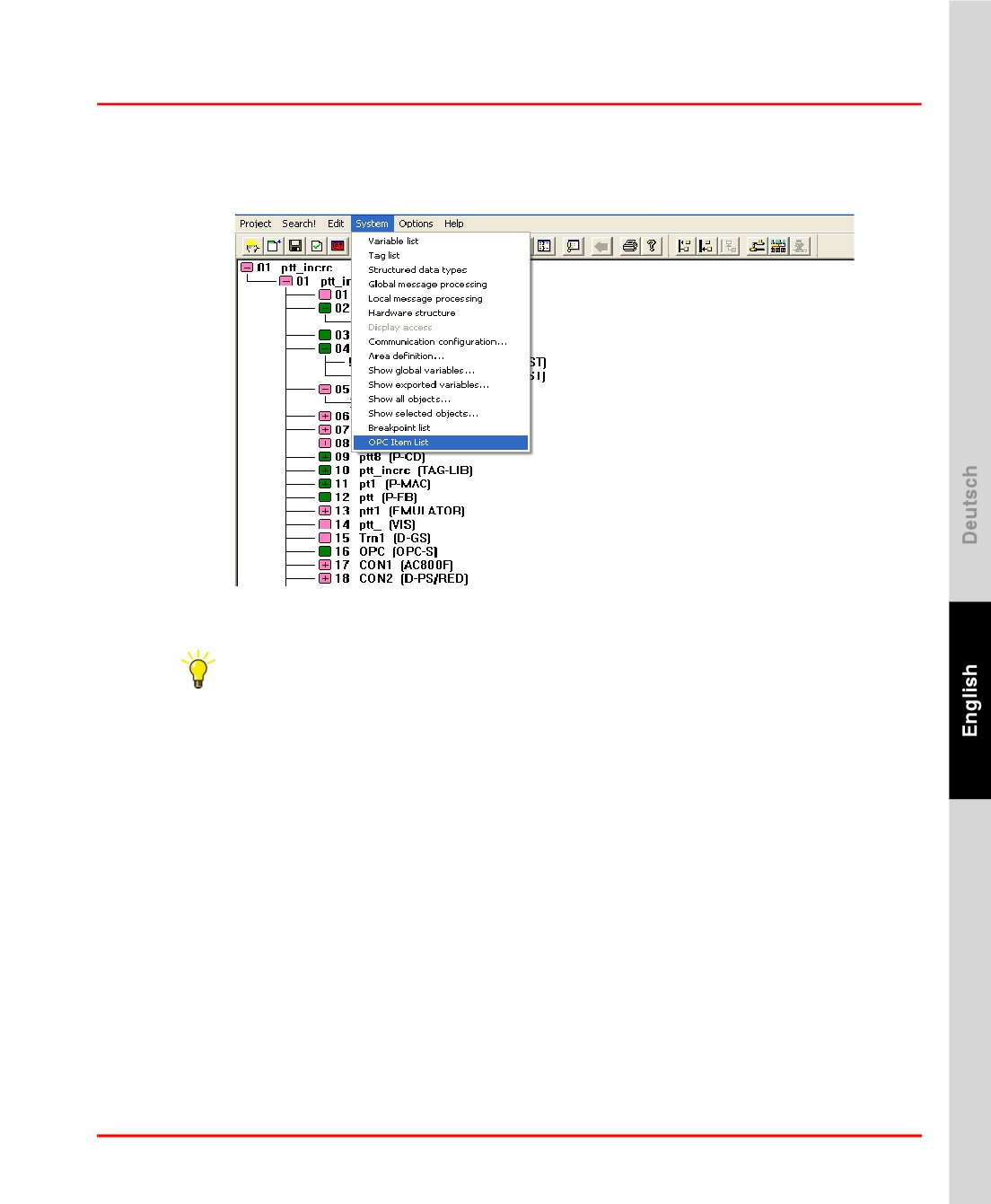
Browsing and adding items to the OPC Item list
OPC_First_Steps_OPC_Item_List.bmp
Project tree > System > OPC Item List
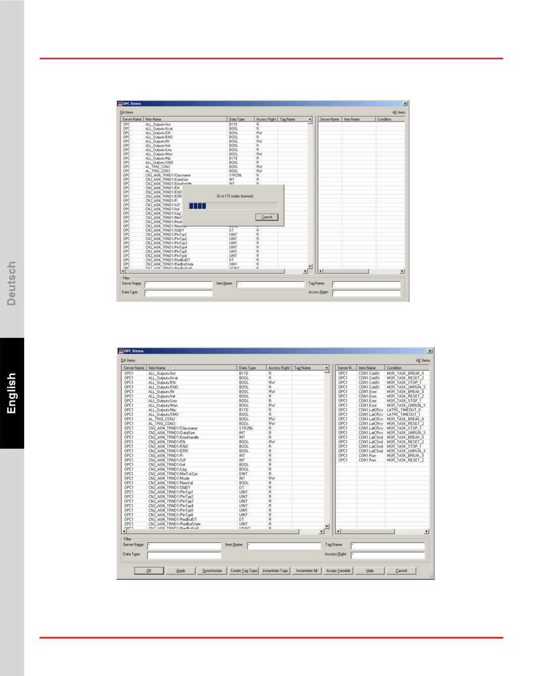
Open OPC Item List and click Synchronize. Select the required OPC server from
the list and click on OK. This will import all the OPC items from the OPC server
into the OPC Item List.
111
Step 8: Working with Tag Types and OPC Items
Section 3 Initial Steps
OPC_Server_Synch.bmp
The OPC Item List is thus populated with items from the OPC server.
OPCitem_browsed.bmp
112
Section 3 Initial Steps
Step 8: Working with Tag Types and OPC Items
Instantiate Tags
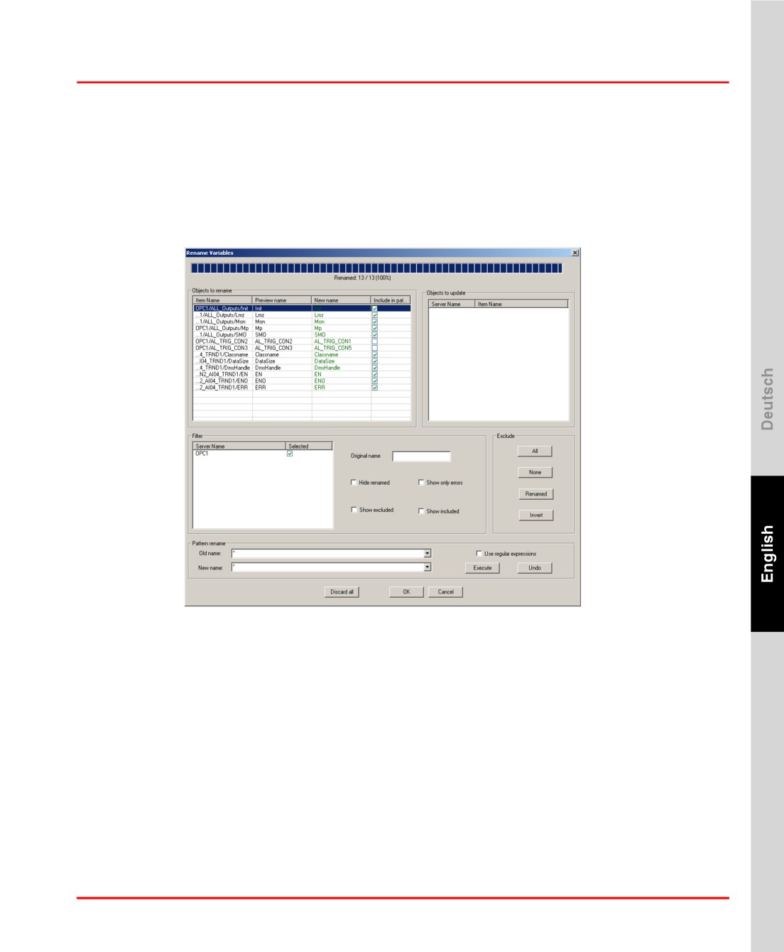
Instantiate Tags using the Instantiate All button in the OPC Item List. This will
match the OPC Items (the “selector” part of the OPC Item name after the separator)
in the Item list with that in the Tag Type library and lists the Tags using Tag Type
selector matching. The list of tags with proposed tag names are listed in a Rename
dialog as shown below
OPC_Server_Rename.bmp
Specify the Tag names for these OPC items in the New name column and click on
OK. The tags linked to the corresponding OPC Items are created in the Tag list.
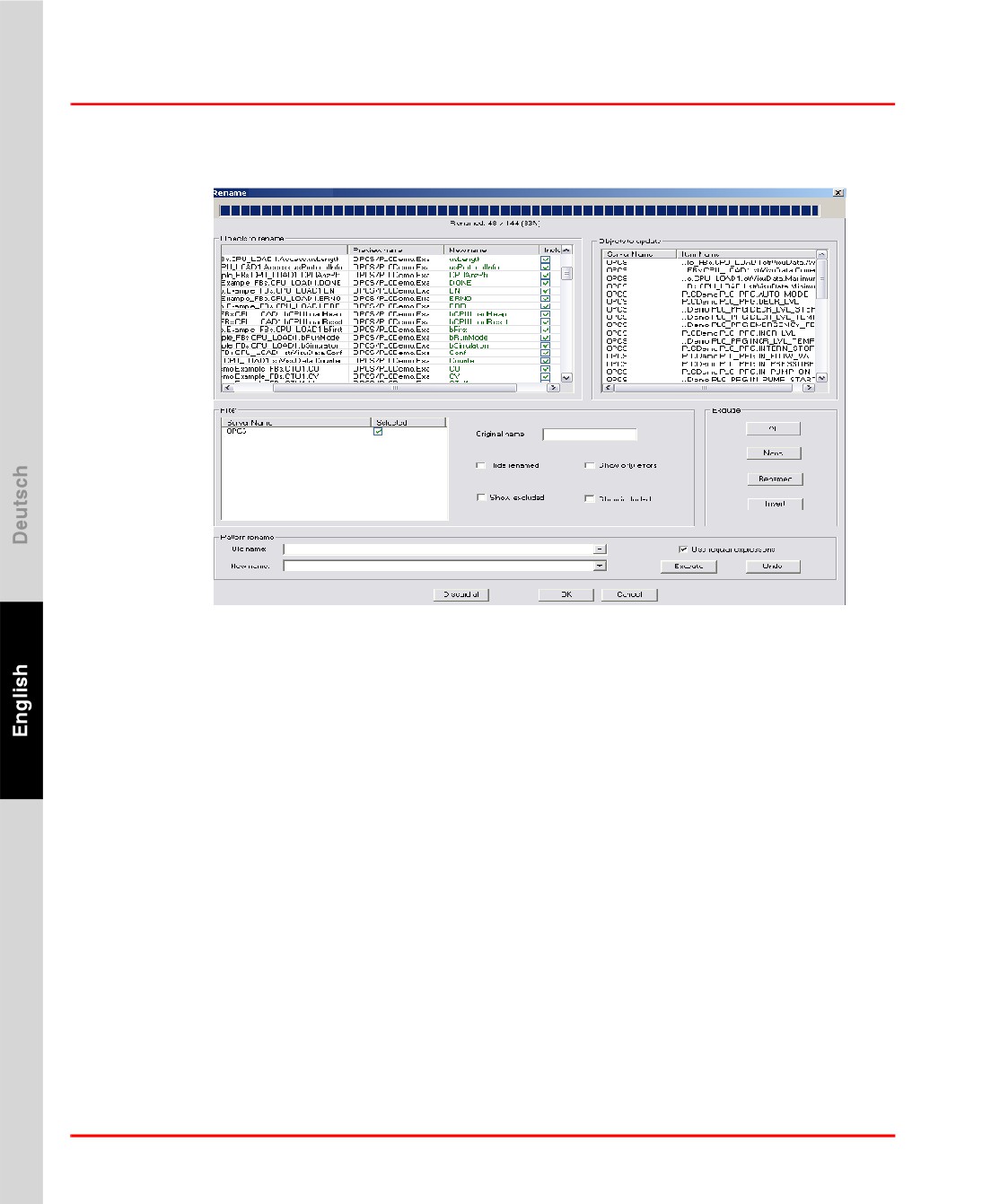
Assign Variables
Select the OPC Items from the OPC item list that are to be used in free graphics/
trends and assign variables to them. A new window suggesting variable names for
the OPC item opens as below.
113
Step 8: Working with Tag Types and OPC Items
Section 3 Initial Steps
OPC_Items_Assign_Variable.bmp
Specify the required “variable name” in the New name column and click on OK. All
the OPC Items with the suggested name will be assigned as a variable in the
variable list.
User can configure free graphics and Trend from the Tags and Variables created
above.
114
Index
A
I
Authorization key installation
68
I/O EPROM import
71
Automation Sentinel
20
Installation
Authorization key
68
B
Check
79
Base License
19
Customize
66
Printer
75
Upgrade
41
C
IP address
67
Configure Tool
66
L
D
License Agreement
50
Default language
68
License Expansion
20
Demo Mode
27,
67
Licensing
13
DigiCheck
79
Load
DigiVis
HSE module EPROM
70
Autostart
74
Profibus module EPROM
70
Settings
74
Load HSE module EPROM
70
Dimensions and message text
72
Load Profibus module EPROM
70
Dual monitor support
19
N
E
Network Protocol
36
Emergency mode
27
EPROM download
70
O
OPC Item list
F
Instantiate Tags
113
FTP Server
OPC Items
Windows 7
90
Browsing
111
Windows XP
86
Tag Instantiation
113
OPC Server Configuration
110
H
OPC Tunnel
80
Hardkey
27
Configuration
82
Hotline
23
Diagnostics
83
115
Index
Installation
81
System Tray
83
Optional Licenses
19
P
Page layout
72
Production Mode
67
S
Settings
Control Builder F
69
DDE
76
DigiBrowse
75
Setup
Start
46
Solution Bank Sentinel
21
Step-up
20
Subnet mask
67
For time synchronization
37
T
Tag Type Library
109
Time synchronization
67
U
Upgrade
20
Use host names
38
User account
67
W
Wave files for Alarms
52
WEB display runtime
19
116
Freelance
Getting Started
Version 9.2 SP1
HINWEIS
Die Informationen in diesem Dokument können ohne Vorankündigung geändert werden
und stellen keinerlei Verpflichtung seitens ABB dar. ABB übernimmt keinerlei Haftung für
möglicherweise in diesem Dokument enthaltene Fehler.
ABB übernimmt keinerlei Haftung für mittelbare, unmittelbare, besondere, zufällig oder in
der Folge auftretende Schäden jeglicher Art, die auf den Gebrauch dieses Dokumentes
zurückzuführen sind. Des Weiteren übernimmt ABB keine Haftung für zufällige oder Fol-
geschäden, die aus dem Gebrauch der in diesem Dokument beschriebenen Hard- und
Software entstehen.
Eine Vervielfältigung dieses Dokumentes oder von Teilen daraus bedarf der vorherigen
schriftlichen Genehmigung von ABB. Der Inhalt dieses Dokumentes darf nicht an Dritte
weitergegeben noch einem nicht bestimmungsgemäßen Gebrauch zugeführt werden.
Die Lieferung der in diesem Dokument beschriebenen Soft- und Hardware erfolgt gemäß
den Bestimmungen der Lizenzvereinbarung. Die Verwendung, Vervielfältigung und Wei-
tergabe unterliegt ebenfalls den Bestimmungen der Lizenzvereinbarung.
Dieses Produkt entspricht den Anforderungen der EMV-Richtlinie 89/336/EEC und der
Niederspannungsrichtlinie 72/23/EEC.
Copyright © 2010 ABB.
Alle Rechte vorbehalten.
Veröffentlichung:
Dezember 2010
Dokumentennummer:
3BDD012560R0503
Warenzeichen
Alle Rechte an den in diesem Dokument genannten Warenzeichen und registrierten
Warenzeichen sind deren Inhabern vorbehalten.
Inhaltsverzeichnis
Hinweise zu diesem Handbuch
Vorsicht-, Achtung-, Information- und Tipp-Symbole
9
Typographische Konventionen
10
Schreibkonventionen
10
Terminologie
11
Zugehörige Dokumentation
11
Kapitel 1 - Lizenzierung
Einleitung
13
Control Builder F
13
Control Builder F Standard
14
Control Builder F Professional
14
Freelance Prozess-Stationen
15
Control-Software-Lizenz Basic
15
Control-Software-Lizenz Advanced
16
Weitere Control-Software-Optionen
17
Lizenzierung der verwendeten E/As
17
Basislizenz
19
Optionale Lizenzen
19
Upgrades von früheren Software-Versionen
20
Software-Management-Programm Automation-Sentinel für Freelance
21
Kapitel 2 - Installation Freelance
Allgemeine Hinweise
23
Freelance-Support
23
Empfohlene PC Ausstattung
24
Produktoptionen
26
Optionen und Zusatzmodule
26
5
Inhaltsverzeichnis
Hardkey
26
Erstinstallation der Freelance-Software
27
Checkliste für die Installation
27
Installation des Windows Betriebssystems
29
Manuelle Deaktivierung der Benutzerkontensteuerung
29
Windows-Firewall
29
Automatische Updates deaktivieren
31
Energieoptionen konfigurieren
32
Bildschirmschoner deaktivieren
33
Für die Installation von DigiVis: Bildschirmauflösung einstellen
33
Für die Installation von DigiVis: Zusätzliche Einstellungen für die
Zugangssperre zum Betriebssystem
35
Netzwerkeinstellungen und IP-Adressen
36
Benutzerkonto einrichten
41
Konfiguration des Virenscanner-Programms
41
Upgrade einer vorhandenen Version auf die neue Version
42
Vor einem Upgrade zu beachten
42
Upgrade von V9.1 auf V9.2 SP1
44
Upgrade von V9.2 auf V9.2 SP1
45
Deinstallieren vor Neuinstallation
46
Setup starten
47
Freelance -Software installieren
49
Allgemeiner Hinweis zur Vorgehensweise beim Setup
49
Voraussetzungen für die Installation
50
Einstellung der Benutzerkontensteuerung in Windows 7
50
Willkommensseite
52
Lizenzvereinbarung
52
Auswählen der Installationsart
53
Arbeitsstation-Typ im DEMO-Modus
55
Arbeitsstation-Typ im Modus PRODUKTION
56
Benutzerdefinierte Arbeitsstation
57
Freelance-Basis-Software-Pakete
58
6
Inhaltsverzeichnis
Der „Bereit zu installieren“-Dialog
61
Datenbestände von früheren Versionen übernehmen
62
Installationseinstellungen ändern
63
Installation abschließen
64
Wartungsmodus
65
Ändern
66
Reparieren
67
Entfernen
67
Installationseinstellungen anpassen
68
Erstkonfiguration der Freelance-Software
68
Allgemeine Einstellungen
69
Einstellungen für Control Builder F
72
Einstellungen für DigiVis
76
Einstellungen für DigiBrowse
78
Einstellungen für DDE
78
Einstellungen für OPC-Server
79
Einstellungen für Trend-Server
81
Änderungen bestätigen
82
Installation abgeschlossen
82
Überprüfen der Installation mit Check
82
OPC-Tunnel
83
OPC-Tunnel-Server installieren
84
Konfiguration des OPC-Tunnels
85
OPC-Tunnel-System-Tray
86
Diagnose des OPC-Tunnels
86
FTP-Server
87
FTP-Server unter Windows XP
89
FTP Server unter Windows 7
93
FTP-Server testen
98
Java Installation
99
Kapitel 3 - Erste Schritte
Allgemeine Hinweise
101
7
Inhaltsverzeichnis
Erstellung einer Projektdatei
101
1. Schritt: Konfiguration der Software-Sicht des Projekts
102
2. Schritt: Konfiguration der Hardware-Zuordnung
106
3. Schritt: Schritt: Inbetriebnahme
108
4. Test der Konfiguration
109
5. Schritt: Sichern der Projektdaten
111
6. Schritt: Konfiguration einer Leitstation
111
7. Schritt: Inbetriebnahme der Leitstation
112
8. Schritt: Mit Tag-Typen und OPC-Elementen arbeiten
113
Tag Typ-Bibliothek anlegen
113
OPC-Tunnel konfigurieren
114
OPC-Server im CBF konfigurieren
114
Durchsuchen und Elemente zur OPC-Itemliste hinzufügen
116
MSR-Stellen instanziieren
118
Variablen zuordnen
118
Stichwortverzeichnis
8