LoongArch Reference Manual. Volume 1: Basic Architecture (Version 1.02) - page 2
Chapter 1. Introduction
The LoongArch architecture (LoongArch) is an Instruction Set Architecture (ISA) that has Reduced
Instruction Set Computer (RISC) style. The LoongArch Reference Manual is used to explain the LoongArch
specification. This is the first of three volumes, which describes the basic part of LoongArch.
1.1. Overview of LoongArch ISA
LoongArch has the typical characteristics of RISC. LoongArch instructions are of fixed size and have
regular instruction formats. Most of the instructions have two source operands and one destination
operand. LoongArch is a load-store architecture; this means only the load/store instructions can access
memory the operands of the other instructions are within the processor core or the immediate number in
the instruction opcode.
LoongArch is divided into two versions, the 32-bit version (LA32) and the 64-bit version (LA64). LA64
applications are “application-level backward binary compatibility” with LA32 applications. That means LA32
applications can run directly on the machine compatible with LA64, but the behavior of system softwares
(such as the kernel) on the machine compatible with LA32 is not guaranteed to be the same as on the
machine compatible with LA64.
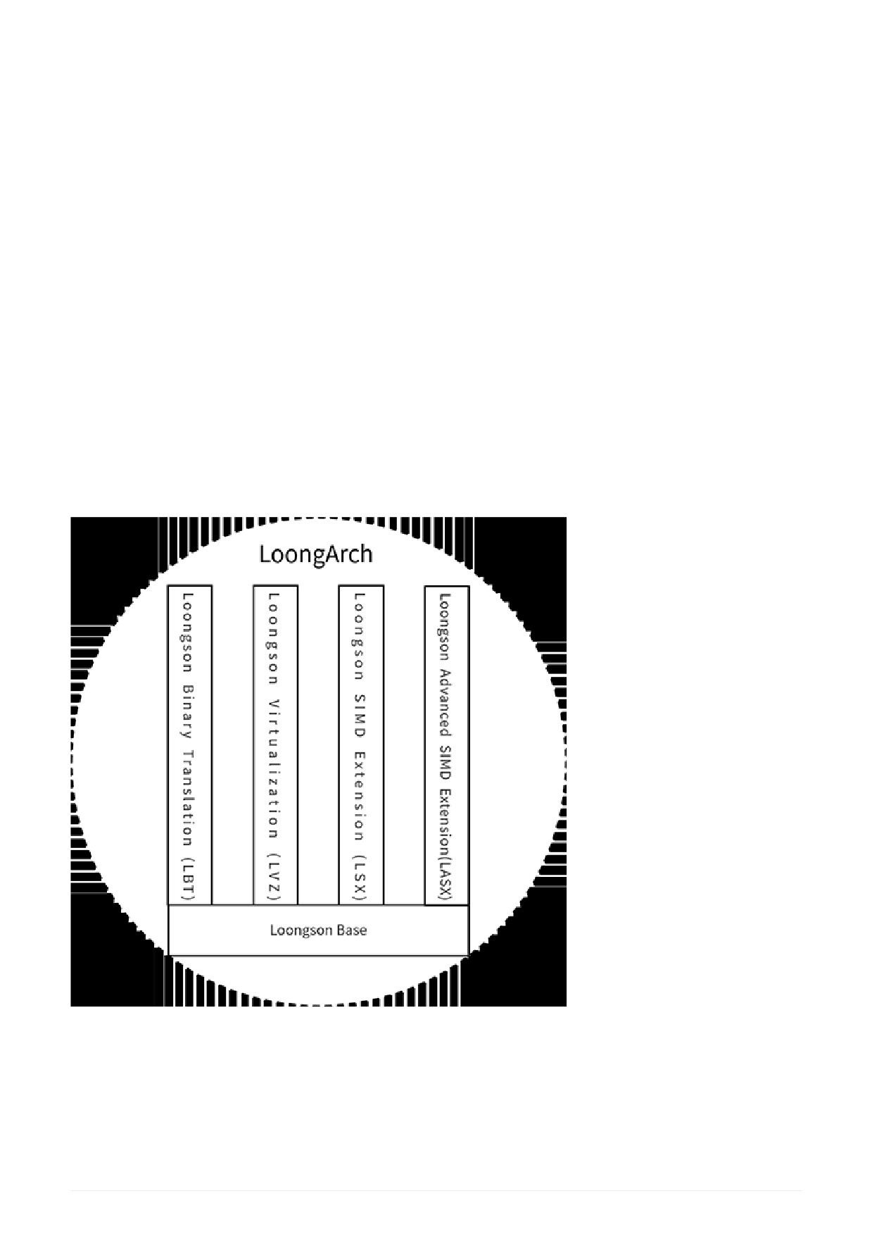
LoongArch is composed of a basic part (Loongson Base) and an expanded part, as shown in the figure. The
expansion part includes Loongson Binary Translation (LBT), Loongson VirtualiZation (LVZ), Loongson
SIMD EXtension (LSX), and Loongson Advanced SIMD EXtension(LASX).
Figure 1. LoongArch components
The basic part of LoongArch includes an non-privileged instruction set and a privileged instruction set. The
non-privileged instruction set defines commonly used integer and floating-point instructions, which can
adequately support the current mainstream compiler to generate efficient target codes.
The virtualization extension part of LoongArch is used for operating system virtualization to provide
hardware acceleration to improve performance. This part involves basically all privileged resources,
7
including some privileged instructions and control and status registers, functions added in exceptions and
interrupts, memory management, and so on.
The binary translation extension part of LoongArch is used to improve the execution efficiency of the cross-
instruction system binary translation on the LoongArch platform. It expands on the basic part and also
includes two parts, the non-privileged instruction set and the privileged instruction set.
LoongArch vector instruction extension and advanced vector instruction extension both use SIMD
instructions to accelerate CPU-bound applications. They are basically the same in terms of instruction
functions. The difference is that the vector length of the vector instruction extension operation is 128 bits
and the vector length of the advanced vector instruction extension operation is 256 bits.
For the architecture compatible with LoongArch, the basic part of the LoongArch must be implemented,
and the extended part can be implemented optionally. Each extension part can be selected flexibly, but
when choosing to implement LASX, LSX must be implemented. Some optional subsets of functions are
included in the basic part and each extension part. The software can detect whether these optional
functions are implemented via the CPUCFG instruction.
The follow-up evolution of the LoongArch adopts a “fine-grained incremental evolution” method. The so-
called “fine-grained” means that each functional subset in the basic part or the extended part can evolve
independently. The so-called “incremental” means that for any part that can be evolved independently, the
higher version is always forward binary compatible[1] with the lower version.
Starting from Chapter 2 of this manual, the specification of the LoongArch will be described in detail. The
contents of Chapter 2 and 3 involve the non-privileged instruction set part of the architecture, including the
function definitions of basic integer instructions and basic floating-point instructions and their application-
level programming models. Chapters 4 to 7 are used to describe the privileged resources in the
architecture, mainly including the introduction of privileged instructions, control and status registers,
function specifications in operating modes, exceptions and interrupts, memory management, and etc. The
pseudo-code descriptions designed to describe the function definitions of instructions are concentrated in
Appendix A. The specific coding definitions of the instructions involved are listed in Appendix B.
1.2. Instruction formats
All LoongArch instructions are fixed 32 bits and required to be aligned on 4-byte boundaries. If the address
of an instruction is not aligned, address error exception will be triggered.
The style of instruction encoding is that all register operand fields are placed in order from low to high
starting from the 0th bit, while the opcode field is placed in order from the 31st bit from high to low. The
immediate field, which has different lengths according to different instruction types, is located between the
register field and the opcode field if the instruction contains an immediate operand. Specifically, it contains
9 typical instruction formats, including 3 formats without immediate data (2R, 3R, and 4R), and 6 formats
with immediate data (2RI8, 2RI12, 2RI14, 2RI16, 1RI21, and I26). The table below lists the specific
definitions of these 9 typical formats. There are a few instructions whose encoding style is not completely
equivalent to these 9 typical instruction formats. However, the number of such instructions is small and the
instructions change little, which will not be inconvenient for compiler developers.
Table 1. Typical Instruction Formats in LoongArch
3
3
2
2
2
2
2
2
2
2
2
2
1
1
1
1
1
1
1
1
1
1
0
0
0
0
0
0
0
0
0
0
1
0
9
8
7
6
5
4
3
2
1
0
9
8
7
6
5
4
3
2
1
0
9
8
7
6
5
4
3
2
1
0
2R-type
opcode
rj
rd
3R-type
opcode
rk
rj
rd
4R-type
opcode
ra
rk
rj
rd
2RI8-type
opcode
I8
rj
rd
2RI12-type
opcode
I12
rj
rd
8
3
3
2
2
2
2
2
2
2
2
2
2
1
1
1
1
1
1
1
1
1
1
0
0
0
0
0
0
0
0
0
0
1
0
9
8
7
6
5
4
3
2
1
0
9
8
7
6
5
4
3
2
1
0
9
8
7
6
5
4
3
2
1
0
2RI14-type
opcode
I14
rj
rd
2RI16-type
opcode
I16
rj
rd
1RI21-type
opcode
I21[15:0]
rj
I21[20:16]
I26-type
opcode
I26[15:0]
I26[25:16]
1.3. Assembly Instruction Mnemonic Formats
The assembly instruction mnemonic mainly includes the instruction name and the operand. LoongArch
considers the prefix and suffix of instruction names and operands to make it easier for assembly
programmers and compiler developers to use.
First, non-vector instructions and vector instructions, as well as integer and floating-point instructions, can
be distinguished by the prefix of instruction name. The instruction name of a 128-bit vector instruction
begins with the letter V; the instruction name of a 256-bit vector instruction begins with the letter XV. The
instruction name of a non-vector floating-point instruction begins with the letter F; the instruction name of a
128-bit vector floating-point instruction begins with VF; the instruction name of a 256-bit vector floating-
point instruction begins with XVF.
Secondly, most instructions use a suffix in the form of .XX in the instruction name to indicate the operand
type of the instruction. This form of suffix is only used to characterize the type of the instruction operand. If
the operand is an integer, the suffixes of the instruction name include .B (signed byte), .H (signed half
word), .W (signed word), .D (signed double word), .BU (unsigned byte), .HU (unsigned half word), .WU
(unsigned word), and .DU (unsigned double word). An exception is that if whether the operand is signed or
unsigned does not affect the result of the operation, the suffix of the instruction name will not carry U. In
this case, the suffix does not limit the operand to the signed number. If operand is a floating-point number,
the suffixes of the instruction name are .H (half precision), .S (single-precision), .D (double-precision), .W
(signed word), .L (signed double word), .WU (unsigned word), .LU (unsigned double word). In addition, for
instructions involving vector operations, the suffix .V of the instruction name indicates that the entire
vector data is operated as a whole. An exception is that if the length of the operand of an instruction is
determined by whether the processor is 32-bit or 64-bit, the instruction name has no suffix, such as SLT
instruction and SLTU instruction. Privileged instructions for operating CSRs, TLB, and Cache, and
instructions for moving data between different register files have no suffix.
If the length and sign of the source operand and the destination operand are the same, the instruction
name will have only one suffix. If the length and sign of all source operands are the same, but not the same
as the destination operand, the instruction name will have two suffixes. From left to right, the first suffix
decorates the destination operand, and the second suffix decorates the source operand. If the source
operation and destination operand are more complicated, the instruction name will list the destination
operand and each source operand in order from left to right. The order is consistent with the order of the
subsequent operands in the instruction mnemonic. For example, in the instruction MULW.D.WU rd, rj,
rk, .D decorates the destination operand rd, and .WU decorates the source operands rj and rk; this
means that the multiplication is to multiply two unsigned words to obtain a double word result which will be
written into rd. For another example, in the instruction CRC.WBW rd, rj, rk, the first .W decorates rd,
.B decorates rj, and the second .W decorates rk; this means that the CRC check operation is to use the
byte message in rj and the 32-bit original check value in rk to generate a new 32-bit check value which
will be written into rd.
Register operands distinguish register files by the first letter. rN refers to general registers; fN refers to
floating-point registers; vN refers to 128-bit vector registers; xN refers to 256-bit vector registers. Among
9
them, N is a number that represents the Nth register.
1.4. Conventions Used in this Manual
1.4.1. Instruction Abbreviation
There are many instructions defined by LoongArch that appear frequently and have similar behaviors.
Generally, they only have some differences in operands. For the convenience of readers, such instructions
are often introduced together. For the sake of brevity, this manual uses abbreviation rules for the
instruction name. {A/B/C} means to use A, B, and C to combine the instruction name. A[B] means to use
A and AB to combine the instruction name. For example, ADD.{W/D} represents two instruction names
ADD.W and ADD.D, while BLT[U] represents two instruction names BLT and BLTU. A more complicated
example is ADD[I].{W/D}, which represents four instruction names ADD.W, ADD.D, ADDI.W and ADDI.D.
Even though instruction names can be abbreviated, it does not mean that their opcode fields have similar
contents.
1.4.2. References to Control and Status Registers
LoongArch defines a series of Control and Status Registers (CSRs), which are used to control the execution
behavior of instructions. Each CSR usually contains several fields. This manual use CSR.%%%%.#### to
refer to the #### field of the control and status register whose name is abbreviated as %%%%. For example,
CSR.CRMD.PLV represents the PLV field in the CRMD register. When the virtualization extension is
implemented, there are two sets of CSRs in the processor, one belongs to the Host and the other belongs to
the Guest. If the two sets of CSRs cannot be distinguished by the context, CSR.XXXX is used to represent
the CSRs of the Host and GCSR.XXXX is used to represent the CSRs of the Guest.
1. Translator’s note: Forward compatibility here may be ambiguous.
10
Chapter 2. Basic Integer Instructions
According to the context of the software runtime, the non-privileged instruction set of the basic part of
LoongArch includes basic integer instructions and basic floating-point instructions. This chapter will
describe the integer instruction part. The basic integer instruction part is the most basic part of the non-
privileged instruction subset.
2.1. Programming Model of Basic Integer Instruction
The basic integer instruction programming model described in this section only involves the operating
environment of the application software, which is always related to some privileged resources. Therefore,
the concept of privileged resources will be introduced where necessary to ensure the completeness of the
description. Although the content of privileged resources is covered here, it will not be expanded in detail.
Readers who need a comprehensive and in-depth understanding can refer to the relevant chapters in the
manual according to the prompts in the text.
2.1.1. Data Types
There are 5 data types operated by basic integer instructions, namely: bit (b), Byte (B, length 8b), Halfword
(H, length 16b), Word (W, length 32b), Doubleword (D, length 64b). In LA32, there are no integer instructions
for operating doubleword. Byte, half-word, word and double-word data types all use two’s complement
encoding.
2.1.2. Registers
The registers involved in basic integer instructions include General Registers (GR) and Program Counters
(PC), as shown in the figure.
Figure 2. GR and PC
2.1.2.1. General-purpose Registers
There are 32 General purpose Registers (GR), denoted as r0-r31, and the value of register r0 is always 0.
The length of GR is recorded as GRLEN. The length of GR in LA32 is 32 bits, and the length of GR in LA64 is
64 bits. There is an orthogonal relationship between basic integer instructions and general registers. That
is, from an architectural point of view, any register operand in this instruction can use any of the 32 GRs.
The only exception is that the destination register implicit in the BL instruction must be r1. In the standard
LoongArch Application Binary Interface (ABI), r1 is as storing the return address of a function call.
11
2.1.2.2. PC
There is only one PC, which records the address of the current instruction. The PC register cannot be
modified directly by instructions, it can only be modified indirectly by branch instructions, exception trap
and exception return instructions. However, the PC register can be directly read as the source operand of
some non-branch instructions. The length of PC is always the same as the length of GR.
2.1.3. Running Privilege Levels
LoongArch defines 4 running Privilege LeVels (PLV), namely PLV0-PLV3. The specific privilege level of the
application is determined by the system software at runtime, and the application cannot accurately aware
this. In LoongArch, the application usually runs on PLV3. For more information about privilege levels, see
Privilege Levels.
2.1.3.1. Privileged Resources Accessible by Applications
Generally speaking, privileged resources cannot be directly accessed by application running at a non-
privileged level, but when RPCNTL1/RPCNTL2/RPCNTL3 in CSR.MISC is set, the CSRRD instruction can be
executed at the privilege level of PLV1/PLV2/PLV3 to read performance monitor counters. For more
information about performance monitor counters, see Control and Status Registers Related to Performance
Monitoring.
2.1.3.2. Disabling of Some Non-privileged Functions
Some non-privileged functions that are enabled by default after power-on reset can be disabled by the
system software during execution. By setting the DRDTL1/DRDTL2/DRDTL3 bits in CSR.MISC to 1, the
execution of RDTIME instructions at the PLV1/PLV2/PLV3 level can be prohibited, or will trigger the
Instruction Privilege error Exception (IPE).
2.1.4. Exceptions and interrupts
Exceptions and interrupts will interrupt the currently executing program and switch the control flow to the
entry of the exception/interrupt handler to start execution. Exceptions are caused by abnormal conditions
that occur during the execution of the instruction, and interrupts are caused by external events (such as
interrupt signal input). In the manual, it will strictly distinguish the two concepts of
“generating an
exception/interrupt” and “triggering an exception/interrupt”. The difference between the two is that the
former does not necessarily cause a change in the control flow, while the latter must change the current
control flow to an entry point of the exception/interrupt handler.
The handling specifications for exceptions and interrupts belong to the privileged resource handling part of
the architecture. Here is a brief introduction to the exceptions that the application can perceive.
• SYStem call exception (SYS): the execution of the SYSCALL instruction will trigger the system call
exception immediately.
• BrEaKpoint exception (BEK): executing the BREAK instruction will trigger a breakpoint exception
immediately.
• Instruction Non-defined Exception
(INE): if the executed instruction code is not defined in the
architecture, or the architecture specification defines the instruction as not existing in the current
context, then the instruction non-defined exception will be triggered immediately.
• Instruction Privilege error Exception (IPE): in addition to the special circumstances listed in Running
Privilege Levels, executing a privileged instruction in the application software will definitely trigger the
instruction privilege level error exception immediately.
• ADdress error Exception (ADE): when the program has a functional error that causes the address of the
instruction fetch or memory access instruction to appear illegal (such as the instruction fetch address
is not aligned on 4-byte boundaries, and the privileged address space is accessed), ADdress error
Exception for Fetching instructions (ADEF) or ADdress error Exception for Memory access instructions
12
(ADEM) will be triggered.
• Floating-Point error Exception (FPE): when the floating-point number instruction is executed, special
processing is required for data exceptions, which can generate or trigger the basic floating-point error
exception. See Floating-Point Move Instructions for more information.
2.1.5. Memory Address Space
Only the virtual address space visible to the application is involved here. The translation of virtual memory
addresses to physical memory addresses is determined by the runtime environment. These contents relate
to the relevant specifications of privileged resources in the architecture and will be introduced in the
second half of this manual. The memory address space on LoongArch is a continuous linear address
space, which is addressed in bytes.
In LA32, the specification of the memory address space that application can access is: 0-231-1.
In LA64, the range of memory address space accessible by application is: 0-2VALEN-1-1. Generally VALEN is
in the range of [40,48]. Application can determine the specific value of VALEN by executing the CPUCFG
instruction to read the VALEN field of the 0x1 configuration word.
When the virtual address of the instruction fetch or memory access instruction in the application exceeds
the above range, ADEF or ADEM will be triggered.
2.1.6. Endian
LoongArch bit designations are always little-endian.
2.1.7. Memory Access Types
LoongArch supports three types of memory access: Coherent Cached (CC), Strongly-ordered UnCached
(SUC) and Weakly-ordered UnCached (WUC). The memory access type used for a location is associated
with the virtual address, which is determined by the Memory Access Type field. The relationship of the
memory access type and MAT field is: 0 - SUC, 1 - CC, 2 - WUC, and 3 - reserved. The memory access type
setting process is transparent to the application.
When using consistent cacheable access type, the accessed object can be either the final memory object
or the caches. This type of access is usually used to access faster.
When using SUC or WUC access, the final memory object can only be directly accessed. The difference
between the two is: SUC access meets sequential consistency, that is, all accesses are executed in strict
accordance with the order in the program and the next memory access operation cannot be started before
the current memory access operation is completely completed. While the WUC read access allows
speculative execution, and WUC written data can be merged inside the processor core to a larger scale
(such as a Cache line) and then written out in a burst mode. Subsequent writes in the merge process can
overwrite the data written earlier.
In LoongArch, only SUC memory access instructions must not have side effects, that is, such instructions
cannot be predictive executed. Software can use this feature to access I/O devices in the system through
SUC type memory access instructions. However, LoongArch allows SUC fetch instruction operations to
have side effects. This means that the access type is a SUC type of fetch instruction operation, even if it
originates from the result of branch prediction, it is allowed to be executed. In order to prevent the out-of-
core memory access operations generated by such speculative execution from erroneously entering the
illegal physical address space, it is necessary to filter out the risky accesses, This will be done on the chip.
The WUC type of access is usually used to accelerate the access to UC memory data, such as video
memory data.
13
2.1.7.1. Cache Coherency Maintenance of Instruction Cache
The Cache coherency between the instruction Cache of a certain processor core and the Cache in other
processor cores or Cache Coherenr I/O Master must be maintained by hardware.
The Cache coherency maintenance between the instruction Cache and the data Cache within the processor
core can be implemented as hardware maintenance. This means that for the self-modifying code, the
software does not need to use the CACOP instruction to maintain the Cache coherency between the
instruction Cache and the data Cache within the same core. However, due to the pipeline structure and
speculative instruction fetching behavior, the software still needs to use the IBAR instruction to ensure that
the instruction fetching must be able to see the execution effect of the store instruction.
2.1.8. Unaligned Memory Access
The fetch addresses of all instruction fetches must be aligned on 4-byte boundaries, otherwise the ADEF
will be triggered.
Except for atomic memory access instructions, integer bound check memory access instructions and
floating-point bound check memory access instructions, other load/store memory access instructions can
be implemented to allow memory access addresses to be unaligned. However, in an implementation that
allows memory access address misalignment, the system mode software can configure the ALCL0-ALCL3
control bits in CSR.MISC to address these load/store memory access instructions at the privilege levels of
PLV0-PLV3. Alignment check is needed, too. For memory accessed instructions that require address
alignment checks, if the address accessed is not naturally aligned, an Address aLignment fault Exception
(ALE) will be triggered.
2.1.9. Overview of Memory Consistency
The memory consistency model of the LoongArch uses the Weak Consistency (WC) model. This section
only gives a brief description of the weak consistency model adopted by the architecture.
In the weak consistency model, synchronization operations need to be distinguished from ordinary memory
accesses. The programmer must use the synchronization operations defined by the architecture to protect
the access to the write shared unit to ensure that multiple processor cores have access to the write shared
unit mutually exclusive. The following restrictions are imposed on the sequence of memory access events:
• The execution of the synchronization operation satisfies the sequence consistency condition. That is,
synchronization operations are executed in all processor cores strictly in the order in which they appear
in the program, and the next synchronization operation cannot be started until the current
synchronization operation is completely completed.
• Before any ordinary memory access operation is allowed to be executed, all synchronization operations
prior to this memory access operation in the same processor core have been completed.
• Before any synchronization operation is allowed to be executed, all ordinary memory access operations
that precede this synchronization operation in the same processor have been completed.
The instructions that can generate synchronous operations in LoongArch include DBAR, IBAR, AM atomic
memory access instructions with DBAR function, and LL-SC instruction pairs.
2.2. Overview of Basic Integer Instructions
This section will describe the functions of application-level basic integer instructions in LA64. For LA32, it
only needs to implement a subset of them. The instruction list contained in this subset is shown in the
table. Because the length of GR in LA32 is only 32 bits, the sign extension operation in “sign extend the 32-
bit result into the general register rd” in the subsequent instruction description is not required.
Table 2. Application-level basic integer instructions in LA32
14
Arithmetic
ADD.W, SUB.W, ADDIW, ALSL.W, LU12L.W, SLT, SLTU, SLTI, SLTUI,
operation
instructions
PCADDI, PCADDU12I, PCALAU12I,
AND, OR, NOR, XOR, ANDN, ORN, ANDI, ORI, XORI,
MUL.W, MULH.W, MULH.WU, DIV.W, MOD.W, DIV.WU, MOD.WU
Bit-shift
SLL.W, SRL.W, SRA.W, ROTR.W, SLLI.W, SRLI.W, SRAI.W, ROTRI.W
instructions
Bit-manipulation
EXT.W.B, EXT.W.H, CLO.W, CLZ.W, CTO.W, CTZ.W, BYTEPICK.W,
instructions
REVB.2H, BITREV.4B, BITREV.W, BSTRINS.W, BSTRPICK.W, MASKEQZ,
MASKNEZ
Branch instructions
BEQ, BNE, BLT, BGE, BLTU, BGEU, BEQZ, BNEZ, B, BL, JIRL
Memory access
LD.B, LD.H, LD.W, LD.BU, LD.HU, ST.B, ST.H, STW, PRELD
instructions
Atomic memory
LL.W, SC.W
access instructions
Barrier instructions
DBAR, IBAR
Other instructions
SYSCALL, BREAK, RDTIMEL.W, RDTIMEH.W, CPUCFG
In addition, for those instructions whose data length of the operation object is GR length, the operation
length is
32 bits in LA32 and 64 bits in LA64. Unless there are special circumstances, no special
instructions will be given in the instruction function description.
2.2.1. Arithmetic Operation Instructions
2.2.1.1. ADD.{W/D}, SUB.{W/D}
Instruction formats:
add.w
rd, rj, rk
add.d
rd, rj, rk
sub.w
rd, rj, rk
sub.d
rd, rj, rk
The ADD.W instruction performs the operation that the [31:0] bit data in the general register rj plus the
[31:0] bit data in the general register rk; the resultant [31:0] bit is sign extension, then written into the
general register rd.
ADD.W:
tmp = GR[rj][31:0] + GR[rk][31:0]
GR[rd] = SignExtend(tmp[31:0],GRLEN)
The SUB.W instruction performs the operation that the [31:0] bit data in the general register rk minus the
[31:0] bit data in the general register rj; the resultant [31:0] bit is sign extension, then written into the
15
general register rd.
SUB.W:
tmp = GR[rj][31:0] - GR[rk][31:0]
GR[rd] = SignExtend(tmp[31:0], GRLEN)
The ADD.D instruction performs the operation that the [63:0] bit data in the general register rj plus the
[63:0] bit data in the general register rk; the result is written into the general register rd.
ADD.D:
tmp = GR[rj][63:0] + GR[rk][63:0]
GR[rd] = tmp[63:0]
The SUB.D instruction performs the operation that the [63:0] bit data in the general register rj minus the
[63:0] bit data in the general register rk; writes the result into the general register rd.
SUB.D:
tmp = GR[rj][63:0] - GR[rk][63:0]
GR[rd] = tmp[63:0]
When the above instructions are executed, no special handling will be done on overflow.
2.2.1.2. ADDI.{W/D}, ADDU16I.D
Instruction formats:
addi.w
rd, rj, si12
addi.d
rd, rj, si12
addu16i.d
rd, rj, si16
The ADDI.W instruction performs the operation that the [31:0] bit data in the general register rj plus the
12-bit immediate si12 sign extension 32-bit data; the resultant [31:0] bit is sign extension, then written
into the general register rd.
ADDI.W:
tmp = GR[rj][31:0] + SignExtend(si12, 32)
GR[rd] = SignExtend(tmp[31:0], GRLEN)
The ADDI.D instruction performs the operation that the [63:0] bit data in the general register plus to the
64-bit data after 12-bit immediate si12 sign-extension; the result is written into the general register rd.
ADDI.D:
16
tmp = GR[rj][63:0] + SignExtend(si12, 64)
GR[rd] = tmp[63:0]
ADDU16I.D shifts the 16-bit immediate sil6 logic to the left by 16 bits and then sign extensions the
resultant data, the result plus [63:0] bit data in the general register rj, and the result of the addition is
written into the general register rd. The ADDU16I.D instruction is used in conjunction with the LDPTR.W/D
and STPTR.W/D instructions to accelerate GOT table-based access in position-independent codes.
ADDU16I.D:
tmp = GR[rj][63:0] + SignExtend({si16, 16'b0}, 64)
GR[rd] = tmp[63:0]
When the above instructions are executed, no special handling will be done on overflow.
2.2.1.3. ALSL.{W[U]/D}
Instruction formats:
alsl.w rd, rj, rk, sa2
alsl.d rd, rj, rk, sa2
alsl.wu rd, rj, rk, sa2
The ALSL.W instruction performs the operation that logical shift the [31:0] bit data in the general register
rj to the left (sa2
+ 1) and it plus the [31:0] bit data in the general register rk; then write the result
into the general register rd after the sign extension.
ALSL.W:
tmp = (GR[rj][31:0] << (sa2+1)) + GR[rk][31:0]
GR[rd] = SignExtend(tmp[31:0], GRLEN)
ALSL.WU logical shift the [31:0] bit data in the general register rj to the left (sa2
+ 1) bit and it plus
the [31:0] bit data in the general register rk; then the result is [31:0] bit zero after expansion, write to
general register rd.
ALSL.WU:
tmp = (GR[rj][31:0] << (sa2+1)) + GR[rk][31:0]
GR[rd] = ZeroExtend(tmp[31:0], GRLEN)
The ALSL.D instruction performs the operation that logical shift the [63:0] bit data in the general register
rj (sa2 + 1) to the left and it plus the [63:0] bit data in the general register rk; then the result is
written into the general register rd.
ALSL.D:
17
tmp = (GR[rj][63:0] << (sa2+1)) + GR[rk][63:0]
GR[rd] = tmp[63:0]
When the above instructions are executed, no special handling will be done on overflow.
When writing assembly, you need to fill in the immediate field with the real shift value, i.e.
TIP
(sa2+1), not the value in the immediate field of the instruction code.
2.2.1.4. LU12I.W, LU32I.D, LU52I.D
Instruction formats:
lu12i.w
rd, si20
lu32i.d
rd, si20
lu52i.d
rd, rj, si12
The LU12I.W instruction performs the operation that splice the 12-bit 0 behind the lowest bit of the 20-bit
immediate si20, then writes it into the general register rd after sign extension.
LU12I.W:
GR[rd] = SignExtend({si20, 12'b0}, GRLEN)
The LU32I.D instruction performs the operation that splice the bit data [31:0] in the general register rd
behind the lowest bit of the 20-bit immediate si20 sign extension data; then the result is written into the
general register rd.
LU32I.D:
GR[rd] = {SignExtend(si20, 32), GR[rd][31:0]}
The LU52I.D instruction performs the operation that splice the [51:0] bit data in the general register rj
behind the lowest bit of the 12-bit immediate sil2 sign extension data; then the result is written into the
general register rd.
LU52I.D:
GR[rd] = {si12, GR[rj][51:0]}
When the above instructions are executed, no special handling will be done on overflow.
2.2.1.5. SLT[U]
Instruction formats:
slt
rd, rj, rk
18
sltu
rd, rj, rk
The SLT instruction performs the operation that compares the data in the general register rj with the data
in the general register rk as signed integers. If the former is smaller than the latter, the value of the general
register rd is set to 1, otherwise it is set to 0.
SLT:
GR[rd] = (signed(GR[rj]) < signed(GR[rk])) ? 1 : 0
The SLTU instruction performs the operation that compares the data in the general register rj with the
data in the general register rk as unsigned integers. If the former is less than the latter, the value of the
general register rd is set to 1, otherwise it is set to 0.
SLTU:
GR[rd] = (unsigned(GR[rj]) < unsigned(GR[rk])) ? 1 : 0
The data length compared by SLT and SLTU is consistent with the length of the general register of the
executing machine.
2.2.1.6. SLT[U]I
Instruction formats:
slti
rd, rj, si12
sltui
rd, rj, si12
The SLTI instruction performs the operation that compares the data in the general register rj and the 12-
bit immediate sil2 sign extension data as a signed integer for size comparison. If the former is smaller
than the latter, the value of the general register rd is set to 1, otherwise it is set to 0.
SLTI:
tmp = SignExtend(si12, GRLEN)
GR[rd] = (signed(GR[rj]) < signed(tmp)) ? 1 : 0
The SLTUI instruction performs the operation that compares the data in the general register rj and the 12-
bit immediate sil2 sign extension data as an unsigned integer for size comparison. If the former is
smaller than the latter, the value of the general register rd is set to 1, otherwise it is set to 0.
SLTUI:
tmp = SignExtend(si12, GRLEN)
GR[rd] = (unsigned(GR[rj]) < unsigned(tmp)) ? 1 : 0
19
The data length compared by SLTI and SLTUI is consistent with the length of the general register of the
executing machine. Note that for SLTUI instructions, immediate data is still sign extended.
2.2.1.7. PCADDI, PCADDU121, PCADDU18l, PCALAU12I
Instruction formats:
pcaddi
rd, si20
pcaddu12i
rd, si20
pcaddu18i
rd, si20
pcalau12i
rd, si20
The PCADDI instruction performs the operation that splice the 2 bit 0 behind the lowest bit of the 20-bit
immediate data si20 and sign extension, the resultant data plus the PC of the instruction; then the result of
the addition is written into the general register rd.
PCADDI:
GR[rd]= PC + SignExtend({si20, 2'b0}, GRLEN)
The PCADDU12I instruction performs the operation that splice the 12-bit 0 behind the lowest bit of the 20-
bit immediate data si20 and signs extension, the resultant data plus the PC of the instruction; then the
result of the addition is written into the general register rd.
PCADDU12I:
GR[rd] = PC + SignExtend({si20, 12'b0}, GRLEN)
The PCADDU18I instruction performs the operation that splice the 18-bit 0 behind the lowest bit of the 20-
bit immediate si20 and signs extension, the resultant data plus the PC of the instruction; then the result of
the addition is written into the general register rd.
PCADDU18I:
GR[rd] = PC + SignExtend({si20, 18'b0}, GRLEN)
The PCALAU12I instruction performs the operation that splice the 12-bit 0 behind the lowest bit of the 20-
bit immediate data si20 and sign extension; the resultant data plus the PC of the instruction; then the
lowest 12 bits of the addition result are erased and written into the general register rd.
PCALAU12I:
tmp = PC + SignExtend({si20, 12'b0}, GRLEN)
GR[rd] = {tmp[GRLEN-1:12], 12'b0}
The data length of the above instruction operation is consistent with the length of the general register of
the executed machine.
20
2.2.1.8. AND, OR, NOR, XOR, ANDN, ORN
Instruction formats:
and
rd, rj, rk
or
rd, rj, rk
nor
rd, rj, rk
xor
rd, rj, rk
andn
rd, rj, rk
orn
rd, rj, rk
The AND instruction performs the bitwise AND operation between the data in the general register rj and
the data in the general register rk; then the result is written into the general register rd.
AND:
GR[rd] = GR[rj] & GR[rk]
The OR instruction performs the bitwise OR operation between the data in the general register rj and the
data in the general register rk; then the result is written into the general register rd.
OR:
GR[rd] = GR[rj] | GR[rk]
The NOR instruction performs the bitwise OR operation between the data in the general register rj and the
data in the general register rk; then the result is written into the general register rd.
NOR:
GR[rd] = ~(GR[rj] | GR[rk])
The XOR instruction performs the bitwise XOR operation between the data in the general register rj and the
data in the general register rk; then the result is written into the general register rd.
XOR:
GR[rd] = GR[rj] ^ GR[rk]
The ANDN instruction performs the operation that reverses the data in the general register rk bit by bit, then
performs the bitwise AND operation with the data in the general register rk and the data in the general
register rj; then the result is written into the general register rd.
ANDN:
GR[rd] = GR[rj] & (~GR[rk])
21