Boeing 737 - 600/700/800/900. Operations Manual (1997 year) - page 56
Flight Management, Navigation -
Controls and Indicators
Boeing 737 Operations Manual
Inertial System
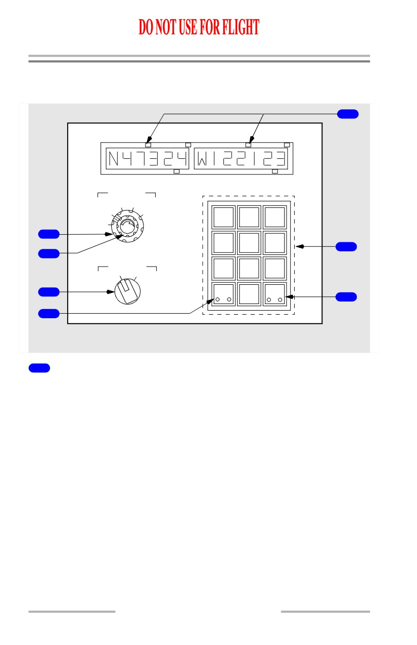
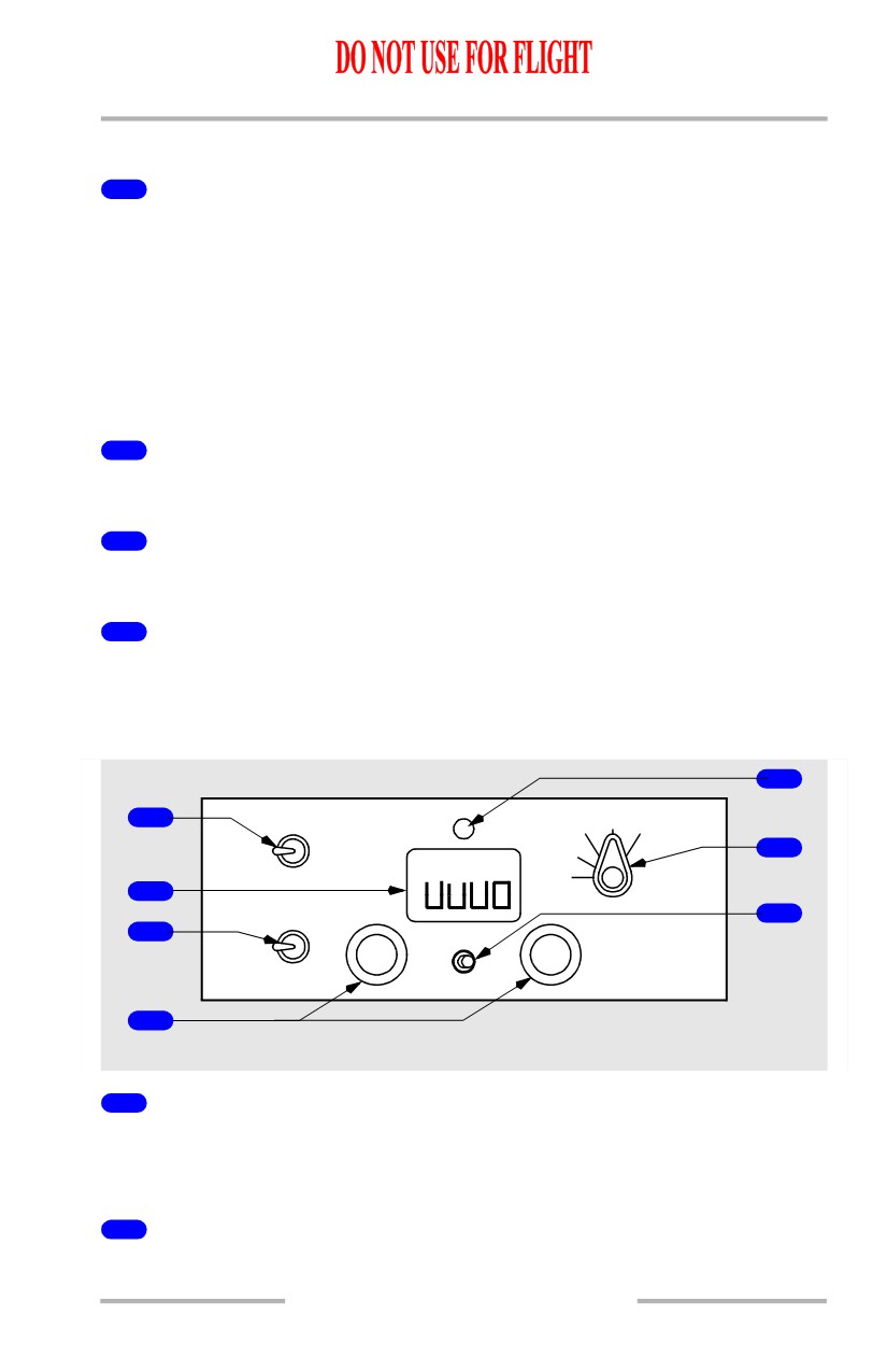
IRS Display Unit (ISDU)
5
IRS DISPLAY
DSPL SEL
PPOS WIND
TK/GS
HDG/STS
N
1
3
2
TEST
BRT
1
W
H
E
4
5
6
6
2
SYS DSPL
S
7
9
L
R
8
3
ENT
CLR
0
7
4
AFT OVERHEAD PANEL
1
Display Selector (DSPL SEL)
TEST (spring-loaded to TK/GS) -
• all lights in data displays and on the mode selector unit momentarily
illuminate, followed by a 10 second self-test
• use only during alignment.
TK/GS -
• left window displays true track (course)
• right window displays present ground speed (knots).
PPOS -
• left window displays present latitude
• right window displays present longitude.
WIND -
• left window displays present inflight true wind direction
• right window displays present inflight wind speed (knots).
11.10.14
Flight Management, Navigation -
Controls and Indicators
Boeing 737 Operations Manual
HDG/STS -
• left window displays present true heading
• right window displays any applicable maintenance status codes
• during alignment, right window displays minutes remaining until
alignment is complete. For alignments greater than 15 minutes, the
window displays 15 until the time remaining reaches 14 minutes. The
display then counts down in one minute intervals.
2
Brightness (BRT) Control
Rotate - adjusts brightness of the data displays.
3
System Display (SYS DSPL) Selector
L - selects left IRS for the data displays.
R - selects right IRS for the data displays.
4
Enter (ENT) Key
Illuminated (white) - N, S, E, W, or H entries are being keyed.
Push - keyed data is entered into IRS following completion of valid self-test for
reasonableness.
5
Data Displays
Two windows display data for the IRS selected with the system display selector
• type of data displayed is normally determined by the display selector
• keyboard entry of present position or magnetic heading overrides the
selected display
• last digit of each window is for a decimal place (tenths).
6
Keyboard
Push -
• alpha keys:
• data displays are controlled by the keyboard when the N, S, E, W
(latitude/longitude) or H (heading) keys are pushed
• pushing an alpha key arms the keyboard for numeric entries.
• numeric keys:
• permit manual entry of present position when ALIGN light is
illuminated
• permit manual entry of magnetic heading when either mode selector is
in ATT.
11.10.15
Flight Management, Navigation -
Controls and Indicators
Boeing 737 Operations Manual
7
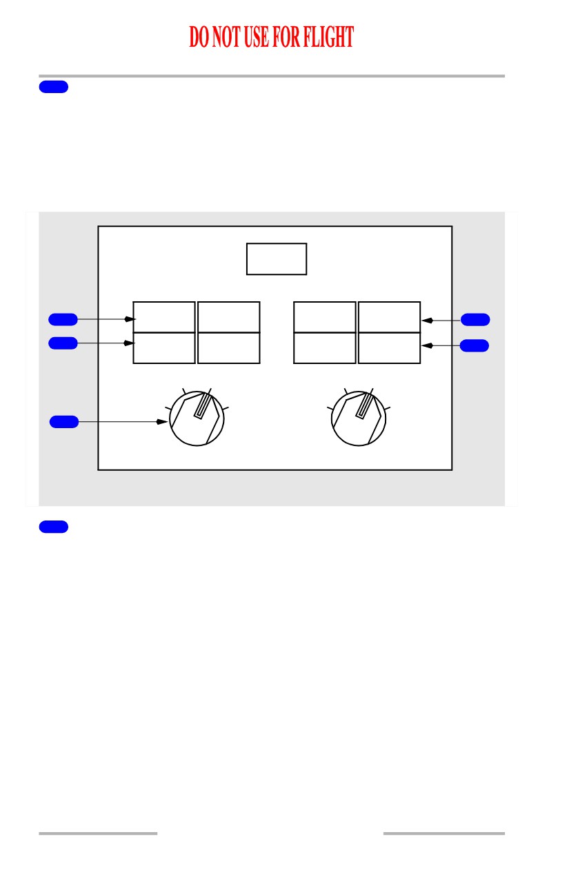
Clear (CLR) Key
Illuminated (white) - an ENT attempt has failed (entry not accepted by IRS).
Push - clears data display of any data not yet entered or accepted. If illuminated,
cue lights extinguish.
IRS Mode Selector Unit
[Option - With GPS]
GPS
1
ALIGN
ON DC
ALIGN
ON DC
4
2
FAULT
DC FAIL
FAULT
DC FAIL
5
ALIGN
NAV
ALIGN
NAV
OFF
ATT
OFF
ATT
3
L IRS R
AFT OVERHEAD PANEL
1
ALIGN Light
Illuminated (white) -
• steady - the related IRS is operating in the ALIGN mode, the initial ATT
mode, or the shutdown cycle
• flashing - alignment cannot be completed due to IRS detection of:
• significant difference between previous and entered positions or an
unreasonable present position entry
• no present position entry.
Extinguished -
• IRS not in ALIGN mode
• with mode selector in NAV, alignment is complete, and all IRS
information is available
• with mode selector in ATT, attitude information is available. Heading
information is available following entry of initial magnetic heading.
11.10.16
Flight Management, Navigation -
Controls and Indicators
Boeing 737 Operations Manual
2
FAULT Light
Illuminated (amber) - a system fault affecting the related IRS ATT and/or NAV
modes has been detected.
3
Inertial Reference System (IRS) Mode Selector
OFF -
• alignment is lost
• all electrical power is removed from the system after a 30 second
shutdown cycle.
ALIGN -
• rotating the selector from OFF to ALIGN initiates the alignment cycle
• rotating the selector from NAV to ALIGN automatically updates
alignment and zeroes ground speed error.
NAV (detented position) -
• system enters the NAV mode after completion of the alignment cycle and
entry of present position
• in NAV mode, all IRS information is available to airplane systems for
normal operations.
ATT - provides only attitude and heading information:
• attitude information is invalid (attitude flag in view) until ALIGN light is
extinguished
• heading information is invalid (heading flags in view) until the actual
magnetic heading is manually entered and the ALIGN light is
extinguished
• position and ground speed information is not available until the IRS is
aligned on the ground
• the selector must be cycled to OFF before reselecting ALIGN or NAV.
4
ON DC Light
Illuminated (amber) -
• the related IRS is operating on DC power from the switched hot battery
bus (AC power not normal)
• if on the ground, the ground-call horn in the nose wheel well sounds,
providing an alert that a battery drain condition exists
• momentary illumination is normal during alignment self-test.
11.10.17
Flight Management, Navigation -
Controls and Indicators
Boeing 737 Operations Manual
5
DC FAIL Light
Illuminated (amber) -
• DC power for the related IRS is not normal
• if the other lights are extinguished, the IRS is operating normally on AC
power.
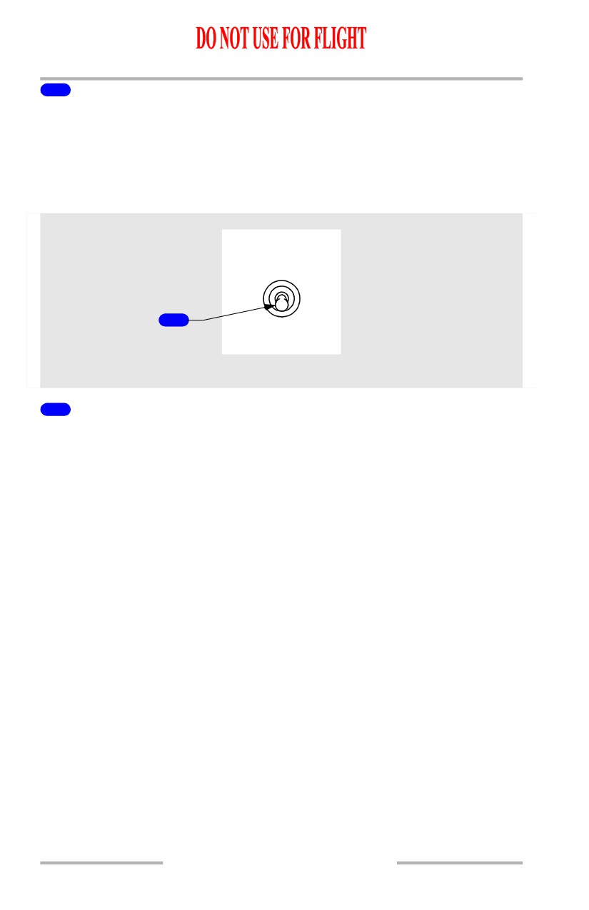
IRS Transfer Switch
IRS
BOTH
BOTH
ON L
ON R
1
NORMAL
FORWARD OVERHEAD PANEL
1
Inertial Reference System (IRS) Transfer Switch
BOTH ON L - switches the flight instruments attitude and heading source to left
IRS.
NORMAL - flight instruments attitude and heading source is from default IRS.
BOTH ON R - switches the flight instruments attitude and heading source to right
IRS.
11.10.18
Flight Management, Navigation -
Controls and Indicators
Boeing 737 Operations Manual
Radio Navigation Systems
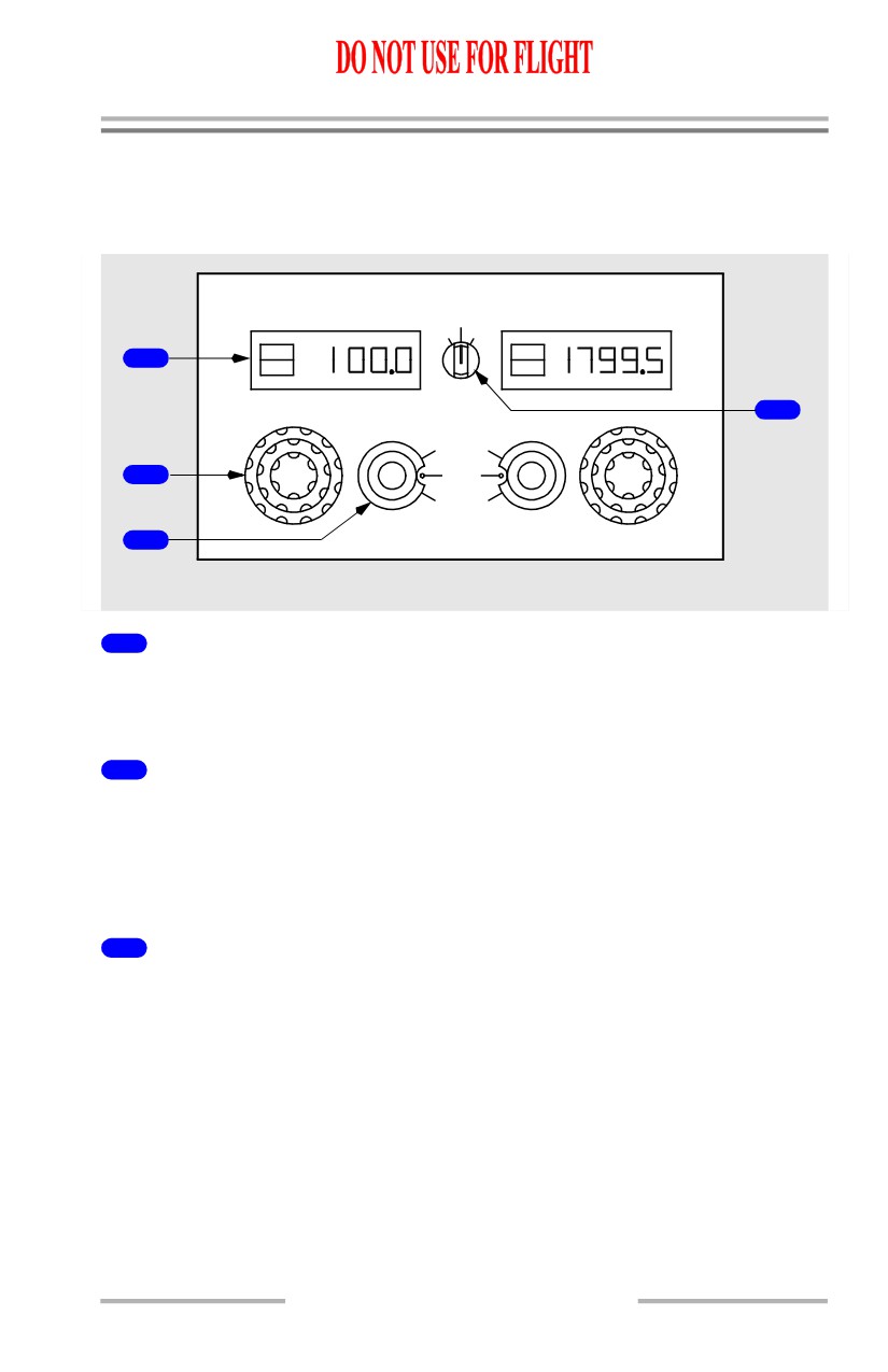
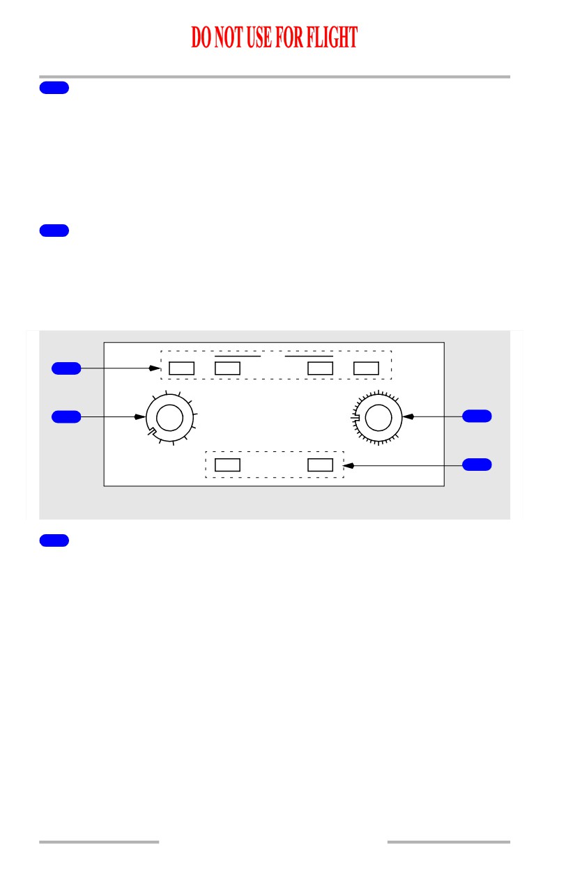
Automatic Direction Finding (ADF) Control
[Option - Gables G7403-03]
ADF 1
ADF 2
OFF
1
2
ADF
ADF
1
ANT
ANT
TONE
4
ADF
2
TEST
ANT
TEST
OFF
3
AFT ELECTRONIC PANEL
1
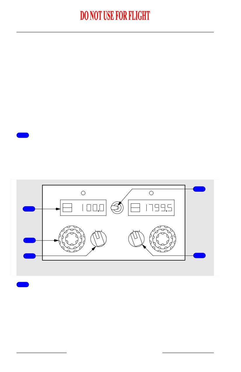
Frequency Indicator
Shows the frequency selected with the related frequency selector.
Shows if the system is in the ADF or antenna (ANT) mode.
2
Frequency Selector
Rotate -
• outer knob sets the hundreds number
• middle knob sets the tens number
• inner knob sets the tenths and ones number.
3
Mode Selector Switch
ADF -
• audio reception possible
• ADF bearing sent to the DUs and the standby radio magnetic indicator.
ANT -
• audio reception optimized
• no ADF bearing data available.
OFF - removes power from selected receiver.
11.10.19
Flight Management, Navigation -
Controls and Indicators
Boeing 737 Operations Manual
TEST - tests related ADF bearing pointers and warning flags on the DUs and the
standby radio magnetic indicator.
• DU ADF indications:
• show ADF fail flag and ADF bearing pointer goes out of view
• ADF fail flag goes out of view and ADF bearing pointer remains out
of view
• ADF bearing pointer slews to 135 degrees relative bearing.
• Standby radio magnetic indicator:
• shows ADF fail flag
• ADF fail flag goes out of view and ADF bearing pointer stays at its
last position before test
• ADF bearing pointer slews to 135 degrees relative bearing.
4
TONE Switch
1 - adds tone to ADF receiver No. 1 audio.
2 - adds tone to ADF receiver No. 2 audio.
OFF - disables tones.
[Option - Gables G7402-02, -05]
5
TFR
ADF
ADF
1
ANT
ANT
A
D
ADF ANT
OFF ON
F
2
TONE
3
4
AFT ELECTRONIC PANEL
1
Frequency Indicator
Shows the frequency selected with the related frequency selector.
Shows if the system is in the ADF or antenna (ANT) mode.
11.10.20
Flight Management, Navigation -
Controls and Indicators
Boeing 737 Operations Manual
2
Frequency Selector
Rotate -
• outer knob sets the hundreds number
• middle knob sets the tens number
• inner knob sets the tenths and ones number.
3
Mode Selector
ADF -
• audio reception possible
• ADF bearing sent to the DUs and the standby radio magnetic indicator.
ANT -
• audio reception optimized
• no ADF bearing data available.
4
TONE Switch
OFF - disables tones.
ON - adds tone to selected ADF receiver audio.
5
Transfer (TFR) Switch
Selects ADF for display.
Marker Beacon Annunciations
[Option - EFIS/MAP]
1
ALT ACQ
HDG SEL
CMD
CAPTAIN’S INSTRUMENT PANEL
1
FIRST OFFICER’S INSTRUMENT PANEL
1
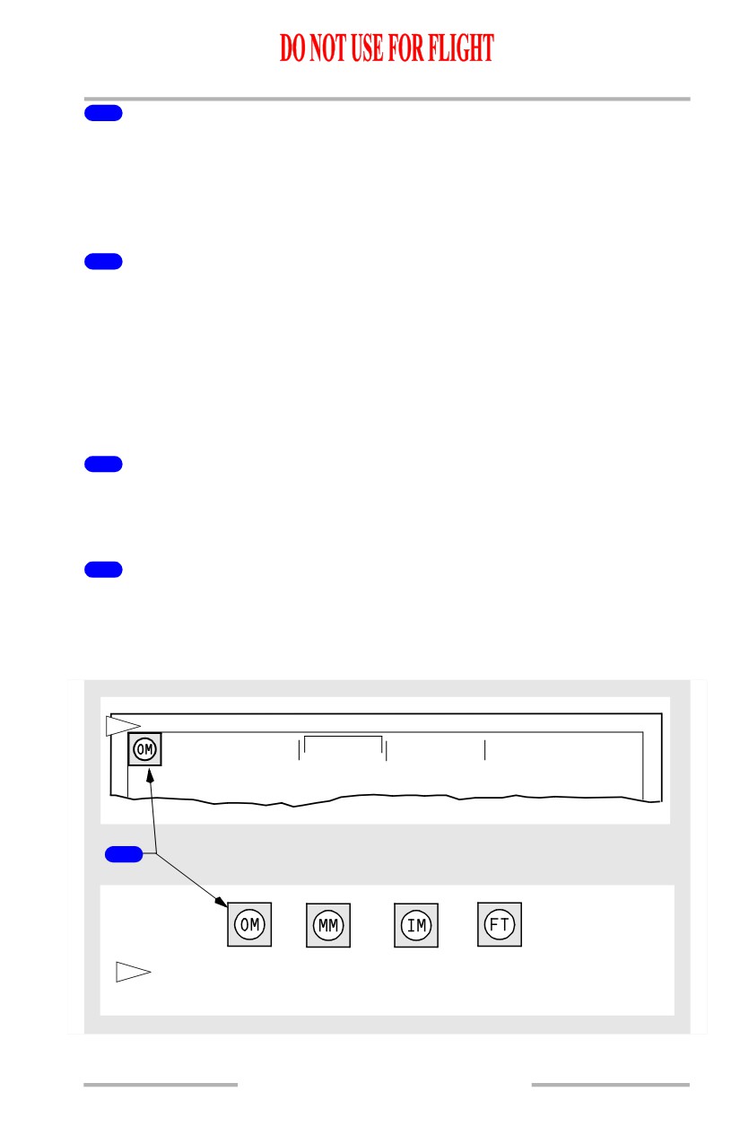
Marker beacon annunciation on right side of First Officer's
display
11.10.21
Flight Management, Navigation -
Controls and Indicators
Boeing 737 Operations Manual
[Option - PFD/ND]
1
CAPTAIN’S INSTRUMENT PANEL
FIRST OFFICER’S INSTRUMENT PANEL
1
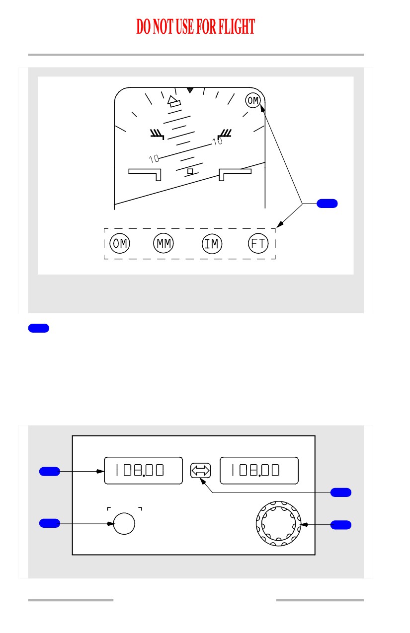
Marker Beacon Lights
OM (cyan) - illuminates over an outer marker beacon.
MM (amber) - illuminates over a middle marker beacon.
IM (white) - illuminates over an inner marker beacon.
FT (white) - illuminates during self test.
VHF Navigation Control
ACTIVE
STANDBY
TFR
1
N
3
A
V
TEST
2
4
AFT ELECTRONIC PANEL
11.10.22
Flight Management, Navigation -
Controls and Indicators
Boeing 737 Operations Manual
1
Frequency Indicator
Indicates the frequency selected by the frequency selector
• tuned frequency displayed in STANDBY display
• TFR switch moves STANDBY frequency to ACTIVE frequency.
2
TEST Switch
With a VOR frequency tuned and a course of 000 selected:
• shows VOR fail flag
• deviation bar biases out of view and then returns to centered position
• bearing pointer slews to 180 degrees.
• DME displays:
• DME fail flag
• dashes
• normal DME distance
With ILS frequency tuned and a course within 90 degrees of airplane heading:
• pointers display one dot up and one dot left
• pointers then display one dot low and one dot right
• pointers then return to normal display.
• DME displays:
• DME fail flag
• dashes
• normal DME distance
3
Transfer (TFR) Switch
TFR - STANDBY frequency moved to ACTIVE frequency; ACTIVE frequency
moved to STANDBY frequency.
4
Frequency Selector
Rotate - manually selects the standby frequency.
11.10.23
Flight Management, Navigation -
Controls and Indicators
Boeing 737 Operations Manual
VHF NAV Transfer Switch
VHF NAV
BOTH
BOTH
ON
1
ON
2
1
NORMAL
FORWARD OVERHEAD PANEL
1
VHF NAV Transfer Switch
BOTH ON 1 - switches the VHF navigation source to VHF NAV receiver No. 1.
NORMAL - VHF navigation source is from default VHF NAV receiver.
BOTH ON 2 - switches the VHF navigation source to VHF NAV receiver No. 2.
Transponder Panel
[Option - AlliedSignal 071-01503-2601]
3
ALT OFF ALT ON
ATC1
ATC
STBY
TA
TEST
TA/RA
6
4
FAIL
5
1
ATC
1
ATC
ALT
2
IDENT
1
2
7
2
AFT ELECTRONIC PANEL
1
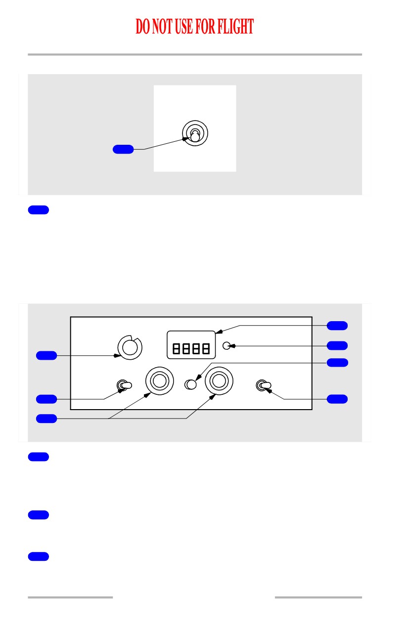
Transponder (ATC) Selector
1 - selects transponder No. 1.
2 - selects transponder No. 2.
2
Air Traffic Control (ATC) Code Selector
Rotate - sets transponder code in transponder.
3
Air Traffic Control (ATC) Code Indicator
Shows transponder code.
11.10.24
Flight Management, Navigation -
Controls and Indicators
Boeing 737 Operations Manual
Shows operating transponder (1 or 2).
4
Transponder Mode Selector
TEST - starts ATC transponder functional test.
STBY (standby) - does not transmit.
ALT (altitude reporting) OFF - transponder operates without altitude reporting.
ALT (altitude reporting) ON - transponder operates with altitude reporting.
TA(traffic advisory) and TA/RA (resolution advisory) - Refer to Chapter 15,
Warning Systems.
5
Identification (IDENT) Switch
Push - transmits an identification signal.
6
Transponder (ATC) FAIL Light
Illuminated (amber) - indicates transponder malfunction.
7
Altitude (ALT) Selector
1 - enables altitude reporting from air data computer No. 1.
2 - enables altitude reporting from air data computer No. 2.
[Option - Gables G6992-02]
6
1
TA ONLY
XPNDR
XPNDR
FAIL
XPNDR
TA/RA
1
2
ALT RPTG
4
OFF
ATC 1
TEST
T
A
STBY
3
C
T
A
C
5
S
7
IDENT
1
2
ALT SOURCE
2
AFT ELECTRONIC PANEL
1
Transponder (XPNDR) Selector
1 - selects transponder No. 1.
2 - selects transponder No. 2.
2
Air Traffic Control (ATC) Code Selector
Rotate - sets transponder code in transponder.
11.10.25
Flight Management, Navigation -
Controls and Indicators
Boeing 737 Operations Manual
3
Air Traffic Control (ATC) Code Indicator
Shows transponder code.
Shows operating transponder (1 or 2).
4
Transponder Mode Selector
TEST - starts ATC transponder functional test.
STBY (standby) - does not transmit.
ALT RPTG (altitude reporting) OFF - transponder operates without altitude
reporting.
XPNDR (transponder) - transponder operates with altitude reporting.
TA (traffic advisory) ONLY, and TA/RA (resolution advisory) - Refer to Chapter
15, Warning Systems.
5
Identification (IDENT) Switch
Push - transmits an identification signal.
6
Transponder (XPNDR) FAIL Light
Illuminated (amber) - indicates transponder malfunction.
7
Altitude (ALT) SOURCE Selector
1 - enables altitude reporting from air data computer No. 1.
2 - enables altitude reporting from air data computer No. 2.
11.10.26

Flight Management, Navigation -
Controls and Indicators
Boeing 737 Operations Manual
Weather Radar Panel
[Option - AlliedSignal 2041223-0414]
WX RADAR
WX WX/TURB
TEST
MAP
TILT
1
5
10
GAIN
UP
15
2
0
3
DN
15
AUTO
MAX
5
10
AFT ELECTRONIC PANEL
1
Mode Selector Switch
Rotate - selects mode.
TEST -
• tests weather radar system operation
• shows test pattern and any fault messages on navigation display MAP,
center MAP, VOR, and APP modes, with WXR selected.
[Option - With predictive windshear]
Note: If the airplane is on the ground and the thrust levers are not advanced for
takeoff, WXR tests the predictive windshear system (PWS) indications.
These include PWS FAIL, PWS caution, and PWS warning. Deactivating
WXR on the EFIS control panel will not discontinue the test and can result
in automatic WXR activation on both pilot displays. The PWS test lasts
approximately 15 seconds.
WX (weather) - shows weather radar returns at selected gain level.
WX/TURB (turbulence) -
• shows weather radar returns
• shows turbulence within 40 miles.
Note: Turbulence detection requires presence of detectable precipitation. Clear
air turbulence cannot be detected by radar.
MAP - shows ground returns.
11.10.27
Flight Management, Navigation -
Controls and Indicators
Boeing 737 Operations Manual
2
GAIN Control
Rotate -
• sets receiver sensitivity to enhance ground mapping in MAP mode only
• system automatically sets gain in other modes.
AUTO (automatic) - gain control is automatic.
MAX (maximum) - reduces amount of ground return.
3
TILT Control
Rotate clockwise- radar antenna tilts up to selected degrees above horizon.
Rotate counterclockwise- radar antenna tilts down to selected degrees below
horizon.
[Option - Collins 622-5129-105]
MODE
1
TEST
WX
WX+T
MAP
-7
-6
10
MIN
5
15
-5
UP
-4
2
GAIN
0
TILT
3
DN
-3
CAL
5
15
-2
MAX
-1
10
IDNT
STAB
1
AFT ELECTRONIC PANEL
1
Mode Switches
Push - selects mode.
TEST -
• tests weather radar system operation without transmitting
• shows test pattern and any fault messages on navigation display MAP,
center MAP, VOR, and APP modes, with WXR selected.
[Option - With predictive windshear]
Note: If the airplane is on the ground and the thrust levers are not advanced for
takeoff, WXR tests the predictive windshear system (PWS) indications.
These include PWS caution, PWS FAIL, and PWS warning. Deactivating
WXR on the EFIS control panel will not discontinue the test and can result
in automatic WXR activation on both pilot displays. The PWS test lasts
approximately 15 seconds.
WX (weather) - shows weather radar returns at selected gain level.
11.10.28
Flight Management, Navigation -
Controls and Indicators
Boeing 737 Operations Manual
WX+T (turbulence) -
• shows weather radar returns
• shows turbulence within 50 miles.
Note: Turbulence detection requires presence of detectable precipitation. Clear
air turbulence cannot be detected by radar.
MAP - shows ground returns.
IDNT - suppresses ground return in WX and WX+T modes.
STAB - antenna tilt automatically adjusts to correct for airplane attitude changes.
2
GAIN Control
Rotate - sets receiver sensitivity in WX, WX+T, and MAP modes.
CAL (calibrated) - presets an optimum receiver sensitivity for best weather radar
display.
3
TILT Control
Rotate clockwise - radar antenna tilts up to selected degrees above horizon.
Rotate counterclockwise - radar antenna tilts down to selected degrees below
horizon.
11.10.29
Flight Management, Navigation -
Controls and Indicators
Boeing 737 Operations Manual
Intentionally
Blank
11.10.30
Boeing 737 Operations Manual
Flight Management, Navigation
Chapter 11
Navigation Systems Description
Section 20
Introduction
[Option - With GPS]
Navigation systems include the flight management system
(FMS); global
positioning system (GPS); air data inertial reference system (ADIRS); radio
navigation systems (ADF, DME, ILS, marker beacons, and VOR); transponder;
and weather radar.
[Option - HUD]
Many of the flight instrument display symbols listed in this chapter also appear on
the Heads Up Display (HUD) System. Refer to Chapter 10, Flight Instruments, for
HUD system display symbol descriptions.
Flight Management System
The flight management system (FMS) is comprised of the following components:
• flight management computer system (FMCS)
• autopilot/flight director system (AFDS)
• autothrottle (A/T)
• inertial reference systems (IRS)
• global positioning system (GPS).
Each of these components is an independent system, and each can be used
independently or in various combinations. The term FMS refers to the concept of
joining these independent components together into one integrated system which
provides continuous automatic navigation, guidance, and performance
management.
The integrated FMS provides centralized flight deck control of the airplane’s
flight path and performance parameters. The flight management computer, or
FMC, is the heart of the system, performing navigational and performance
computations and providing control and guidance commands.
[Option - Dual FMC]
The primary flight deck controls are the AFDS MCP, two control display units
(CDU’s), two electronic flight instrument system (EFIS) control panels, and an
FMC source selector switch. The primary displays are the CDUs, outboard display
units, inboard display units, and upper display unit.
October 15, 2001
11.20.1
Flight Management, Navigation -
Navigation Systems Description
Boeing 737 Operations Manual
[Option - Single FMC]
The primary flight deck controls are the AFDS MCP, two control display units
(CDU’s), two electronic flight instrument system (EFIS) control panels. The
primary displays are the CDUs, outboard display units, inboard display units, and
upper display unit.
The FMC uses crew entered flight plan information, airplane systems data, and
data from the FMC navigation database and performance database to calculate
airplane present position, and pitch, roll, and thrust commands required to fly an
optimum flight profile. The FMC sends these commands to the autothrottle,
autopilot, and flight director. Map and route information are sent to the respective
pilot’s navigation displays. The EFIS control panels are used to select the desired
information for navigation display. The mode control panel is used to select the
autothrottle, autopilot, and flight director operating modes.
Global Positioning System (GPS)
[Option]
Two GPS receivers receive GPS satellite positioning signals. The left and right
GPS receivers are independent and each provides an accurate airplane
geographical position to the FMC and other aircraft systems. GPS operation is
automatic.
GPS Displays
POS REF page 2/3 shows the left and right GPS latitude and longitude position.
POS SHIFT page 3/3 shows the left and right GPS position relative to the FMC
position. NAV STATUS page 1/2 shows the GPS currently in use by the FMC for
position calculation.
[Option - EFIS/MAP]
When the navigation display plan mode is selected and POS SHIFT page 3/3 is
displayed, the navigation display shows the left and right GPS symbols. The GPS
symbols are identical and show as a single symbol when the GPS receivers
calculate the same position.
[Option - PFD/ND]
When the POS (position) switch on the EFIS control panel is selected, the
navigation display shows the left and right GPS symbols. The GPS symbols are
identical and show as a single symbol when the GPS receivers calculate the same
position.
An amber GPS light illuminates to indicate a failure of both GPS sensor units.
Failure of a single GPS sensor causes the light to illuminate when either system
annunciator panel is pushed.
11.20.2
October 15, 2001
Flight Management, Navigation -
Navigation Systems Description
Boeing 737 Operations Manual
GPS Data
FMC logic selects the position from one of the GPS sensor units as the primary
update to the FMC position. When GPS position data is available, radio updating
can also occur. If all GPS data becomes unavailable, the FMC position will be
determined by radio or inertial (IRS) updating.
GPS navigational information can be manually deselected on the NAV OPTIONS
page 2/2. No other controls are provided because the operation of the GPS is
completely automatic.
October 15, 2001
11.20.3