Boeing 737 - 600/700/800/900. Operations Manual (1997 year) - page 57
Flight Management, Navigation -
Navigation Systems Description
Boeing 737 Operations Manual
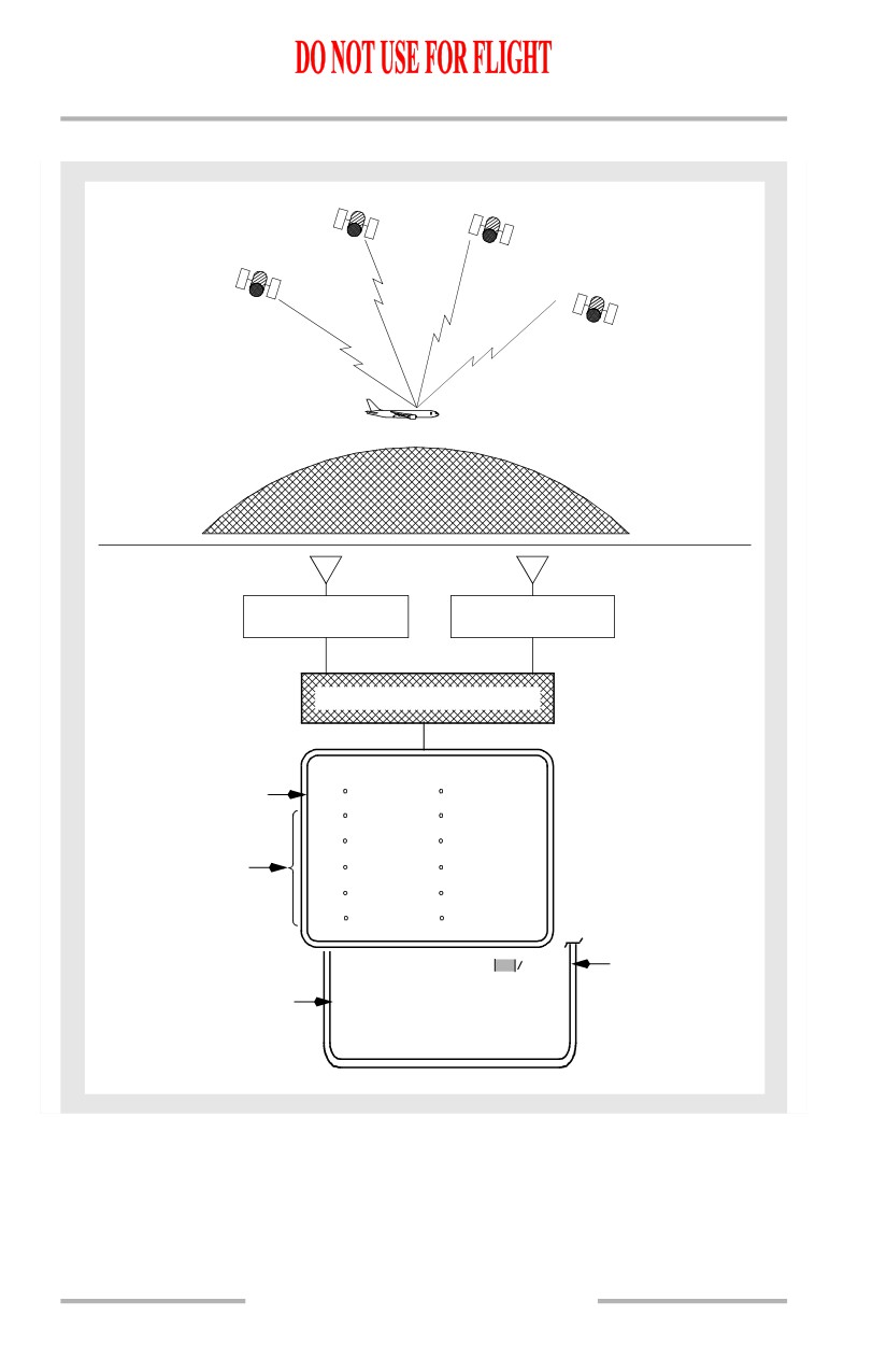
GPS System Schematic
GPS
GPS
TRANSMITTER
TRANSMITTER
GPS
TRANSMITTER
GPS
TRANSMITTER
GPS
SENSOR UNITS
ANTENNA
ANTENNA
GPS SENSOR UNIT
GPS SENSOR UNIT
LEFT
RIGHT
FLIGHT MANAGEMENT COMPUTER
POS RE
F
2 / 3
F M C
P
O
S
G S
FMC Position
N47
32
4
W122
18.6
437
K T
I R
S
L
N47
32
4
W122
18
6
435
K T
I R
S
R
N47
32.4
W122
18
7
438
K T
Nav Sensor
G P S
L
Positions
N47
32
4
W122
18
6
G P S R
N47
32.4
W122
18
6
R A D I O
N47
32
4
W122
18
8
G P S U P D A T E
ON
OFF
>
GPS UPDATE
ON/OFF
NAV OPTIONS
2/2
11.20.4
October 15, 2001
Flight Management, Navigation -
Navigation Systems Description
Boeing 737 Operations Manual
Inertial System
The inertial system computes airplane position, ground speed, and attitude data for
the DUs, flight management system, autoflight system, and other systems. The
major components of the inertial system are the air data inertial reference units
(ADIRU), an inertial system display unit (ISDU), IRS mode select unit (MSU),
and an IRS transfer switch. For information about the air data part of the system,
see chapter 10. The ADIRUs provide inertial position and track data to the FMC,
and attitude, altitude, and airspeed data to the CDS. Each ADIRU has an IRS
section and an air data section.
Inertial Reference System
Two independent IRSs are installed. Each IRS has three sets of laser gyros and
accelerometers. The IRSs are the airplane’s sole source of attitude and heading
information, except for the standby attitude indicator and standby magnetic
compass.
In their normal navigation mode, the IRSs provide attitude, true and magnetic
heading, acceleration, vertical speed, ground speed, track, present position, and
wind data to appropriate airplane systems. IRS outputs are independent of external
navigation aids.
IRS Alignment
An IRS must be aligned and initialized with airplane present position before it can
enter the navigation mode. The present position is normally entered through the
FMC CDU. If the present position cannot be entered through the FMC CDU, it
may be entered through the ISDU keyboard. The airplane must remain stationary
during alignment.
Normal alignment between 78 degrees 15 minutes North or South is initiated by
rotating the MSU switch from OFF to NAV. The IRS performs a short power test,
during which the ON DC light illuminates. When the ON DC light extinguishes
and the ALIGN light illuminates, the alignment process begins. Airplane present
position should be entered at this time. Alignment time varies from five minutes
to seventeen minutes depending on airplane latitude.
Magnetic variation between 82 degrees north and 82 degrees south is stored in
each IRS memory. The data corresponding to the present position are combined
with the true heading to determine magnetic heading.
If the latitude/longitude position is not within 4 NM of the origin airport, the CDU
scratchpad message VERIFY POSITION is displayed. If the entered
latitude/longitude position does not pass the IRS internal comparison tests, the
scratchpad message ENTER IRS POSITION is displayed.
October 15, 2001
11.20.5
Flight Management, Navigation -
Navigation Systems Description
Boeing 737 Operations Manual
The flashing ALIGN light alerts the crew that the position entered does not pass
one of the two internal comparison tests and should be checked for accuracy. If the
entered position does not agree with the last stored position, the first internal test
is failed, and the ALIGN light will flash. If the same position is reentered, the IRS
will accept the position and continue the alignment process. A second internal
position test compares the entered latitude with the system-computed latitude. If
this test is failed, the ALIGN light will again flash. If two consecutive entries of
the same position do not pass the second internal position test, the FAULT light
will illuminate. If the test is passed, the IRS will proceed to complete the
alignment process and enter NAV mode.
During transit or through-flight stops with brief ground times, a thirty second fast
realignment and zeroing of ground speed error may be performed by selecting
ALIGN while the airplane is parked. Present position should be simultaneously
updated by manually entering latitude and longitude prior to selecting NAV.
Note: If the airplane is moved during alignment or fast realignment, the IRS
automatically begins the full alignment process.
Loss of Alignment
If an IRS loses both AC and DC power, the alignment is lost. Alignment can be
lost if the MSU switch is moved out of the NAV position.
If alignment is lost in-flight, the navigation mode (including present position and
ground speed outputs) is inoperative for the remainder of the flight. However,
selecting ATT allows the attitude mode to be used to relevel the system and
provide an attitude reference. The attitude mode requires approximately thirty
seconds of straight and level unaccelerated flight to complete releveling. Some
attitude errors may occur during acceleration, but will be slowly removed after
acceleration stops.
The attitude mode can also provide heading information, but to establish compass
synchronization the crew must manually enter the initial magnetic heading. Drift
of up to 15 degrees per hour can occur in the IRS heading. Therefore, when in
attitude mode, an operating compass system must be periodically cross-checked
and an updated magnetic heading entered in the IRS, as required.
IRS Entries
Manual IRS entries of present position or magnetic heading are normally
accomplished on the POS INIT page of the FMC/CDU. The ISDU may also be
used.
11.20.6
October 15, 2001
Flight Management, Navigation -
Navigation Systems Description
Boeing 737 Operations Manual
IRS Power
The IRSs can operate on either AC or DC power. The left IRS is normally powered
from the AC standby bus, and the right IRS from the AC transfer bus 2. If AC
power is not normal, either or both systems automatically switch to backup DC
power from the switched hot battery bus. Backup DC power to the right IRS is
automatically terminated if AC power is not restored within five minutes.
Initial power-up requires battery bus power available and the IRS mode selector
to be in ALIGN, NAV, or ATT. If the IRS is turned off, it must complete a full
realignment cycle before the airplane can be moved.
If AC electrical power is subsequently removed from the airplane, the switched
hot battery bus continues to supply electrical power to the IRS. The ON DC light
illuminates, and the horn in the landing gear wheel well sounds to alert
maintenance personnel that the IRS is on battery power.
When the IRS mode selector is turned OFF, the IRS remains powered for
approximately 30 seconds. The ALIGN light illuminates until the system is
completely shut down.
Inertial System Display Unit (ISDU)
The ISDU is located on the aft overhead panel and displays data according to the
position of the display selector and system selector. The ISDU also contains a
keyboard for entry of present position and heading.
Mode Select Unit (MSU)
The MSU is located on the aft overhead panel and is used to select the operating
mode for each IRS. Indicator lights on the MSU show status of each IRS.
IRS Transfer Switch
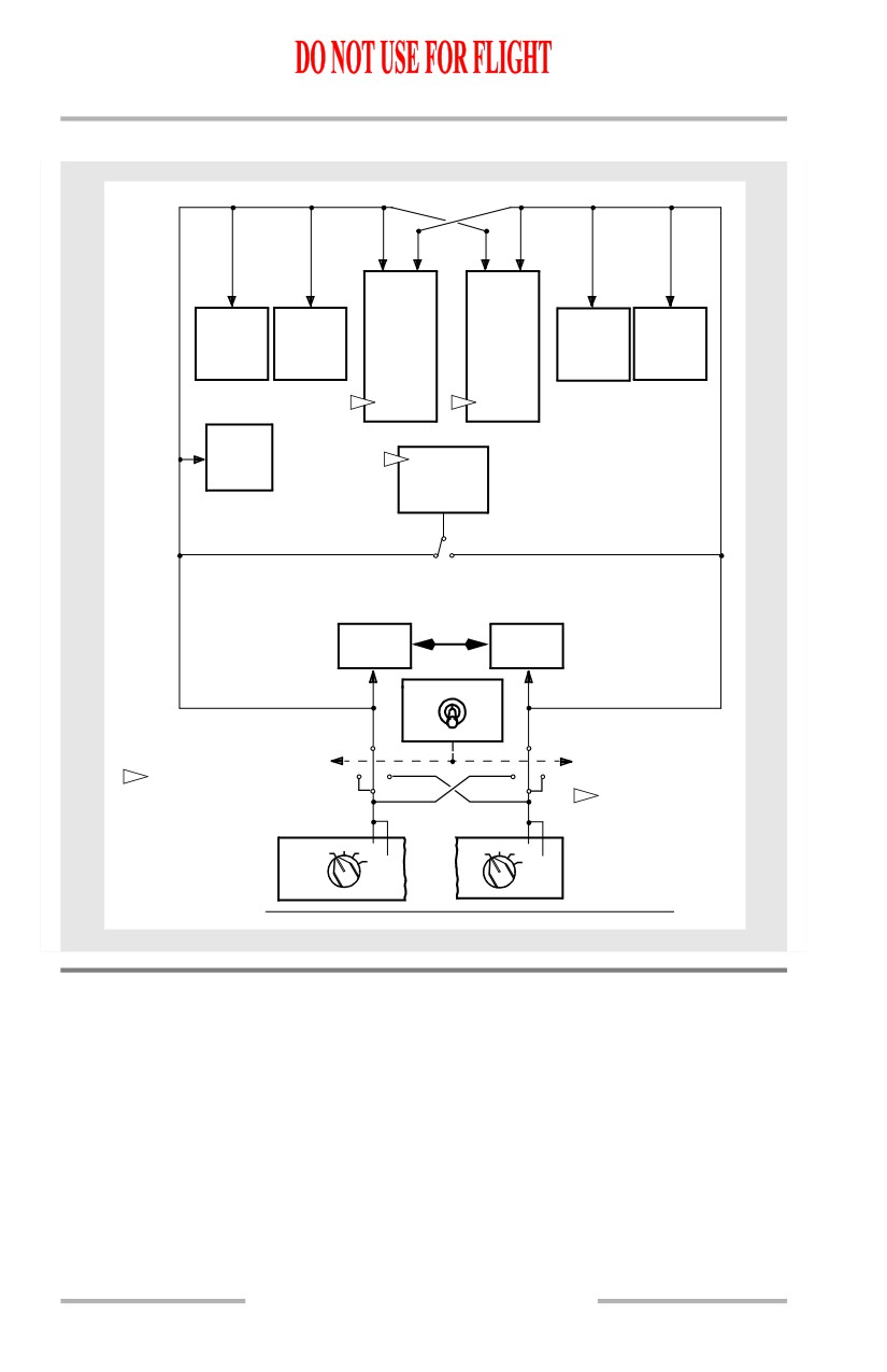
Should either IRS fail, the IRS transfer switch is used to switch all associated
systems to the functioning IRS.
October 15, 2001
11.20.7
Flight Management, Navigation -
Navigation Systems Description
Boeing 737 Operations Manual
IRS Instrument Transfer Switch Schematic
AFDS
AFDS
FLIGHT
FLIGHT
OUTBOARD
INBOARD
CONTROL
CONTROL
INBOARD
OUTBOARD
DISPLAY
DISPLAY
COMPUTER
COMPUTER
DISPLAY
DISPLAY
UNIT
UNIT
A
B
UNIT
UNIT
2
2
WEATHER
RADAR
1
AUTOTHROTTLE
COMPUTER
NO. 1 DEU
NO. 2 DEU
IRS
BOTH
BOTH
ON L
ON R
NORMAL
BOTH
BOTH
ON L
NORMAL
ON R
1
AUTOTHROTTLE
COMPUTER HAS
2
EACH FLIGHT CONTROL
AUTOMATIC SWITCHING
COMPUTER HAS
CAPABILITY BETWEEN
INTERNAL SWITCHING
THE LEFT AND
LOGIC DEPENDENT UPON
RIGHT IRSs
ALIGN
ALIGN
OFF
NAV
OFF
NAV
IRS TRANSFER SWITCH
ATT
ATT
POSITION
L IRS
R
Radio Navigation Systems
Automatic Direction Finding (ADF)
An automatic direction finding (ADF) system enables automatic determination of
magnetic and relative bearings to selected facilities.
[Option - With 2 ADF receivers]
Two ADF receivers are installed. The ADF bearing signals are sent to the pointers
on the DUs and the standby radio magnetic indicator. The audio is heard by using
the ADF receiver control on the audio selector panel.
11.20.8
Flight Management, Navigation -
Navigation Systems Description
Boeing 737 Operations Manual
If heading or track information is lost or invalid, ADF bearing pointers on the DUs
will be removed, and ADF bearing pointers on the standby radio magnetic
indicator will not display correct magnetic bearing. Relative bearings indicated by
pointers may be correct if the receiver is operating.
Distance Measuring Equipment (DME)
Two frequency scanning DME systems are installed.
The FMC autotunes DME receivers as necessary for position updating. During
normal operations, two different DME signals or a signal from a collocated
VOR/DME pair provide an accurate radio geographical position to the FMC. The
identifiers of DMEs currently providing update data to the FMC are displayed on
the NAV STATUS page 1/2. The radio position is displayed on the POS REF page
2/3. Specific DME station tuning for FMC position updating can be inhibited on
the NAV OPTIONS page 2/2.
The flight crew must manually tune the DME on the VHF navigation control panel
and the respective EFIS control panel VOR/ADF switch must be in the VOR
position for DME to be displayed on the CDS. DME distance is also displayed on
the CDS when the ILS receivers are tuned to a collocated DME and localizer
facility.
Instrument Landing System (ILS)
Two ILS receivers are installed.
The ILS receivers are tuned manually on the VHF navigation control panel. The
flight crew must manually tune the ILS for display on CDS. The ILS localizer and
glideslope can also be displayed on the standby attitude indicator.
LOC updating of the FMC occurs only after the ILS is manually tuned.The tuned
ILS frequency is displayed on the navigation display in the APP modes.
Navaid Identifier Decoding
[Option - PFD/ND]
The Morse code identifier of a tuned VOR, ILS, or ADF can be converted to alpha
characters. The decoded identifier is then shown on the PFD and ND. The crew
should monitor this identifier for correct navigation radio reception. The identifier
name is not compared with the FMC database.
Due to the large variation in ground station identifier quality, the decode feature
may incorrectly convert the intended identifier name. Examples: the Hong Kong
localizer “KL” may show as “KAI,” or the Boeing Field ILS may show as “QBFI”
or “TTTT” instead of “IBFI.”
Pilots should verify the identity of the tuned navigation station from the audio
Morse code when the tuned frequency remains shown or an incorrect identifier is
shown.
11.20.9
Flight Management, Navigation -
Navigation Systems Description
Boeing 737 Operations Manual
Marker Beacon
[Option - EFIS/MAP]
Marker beacon indications for outer, middle, and inner marker are displayed on
the upper outboard corner of Captain’s and First Officer’s outboard display units.
[Option - PFD/ND]
Marker beacon indications for outer, middle and inner marker are displayed on the
upper right hand corner of the attitude display located on the Captain’s and First
Officer’s Primary Flight Display (PFD) units.
Very High Frequency Omni Range (VOR)
Two VOR receivers are installed.
The flight crew must manually tune the VOR on the navigation control panel for
display on the DUs and the standby radio magnetic indicator. VOR-DME radio
updating is available if the crew manually tunes a valid in-range VOR station.
[Option - EFIS/MAP]
Left and right VOR bearings are displayed on the DUs when a valid in-range
VOR station is tuned, the respective EFIS control panel VOR/ADF switch is in
the VOR position and the respective EFIS control panel POS switch is pushed.
The DUs also show course deviation.
[Option - PFD/ND]
Left and right VOR bearings are displayed on the DUs when a valid in-range
VOR station is tuned and the respective EFIS control panel VOR/ADF switch is
in the VOR position. The DUs also show course deviation.
VHF NAV Transfer Switch
Should either VOR receiver fail, the VHF NAV transfer switch enables selection
of the opposite VHF NAV receiver for display.
ATC Transponder
Two ATC transponders are installed and controlled by a single control panel. The
ATC transponder system transmits a coded radio signal when interrogated by ATC
ground radar. Altitude reporting capability is provided.
Transmissions are automatically enabled when the air/ground system indicates air
mode.
TCAS is also controlled from the transponder panel. The TCAS system is
described in Chapter 15.
11.20.10
Flight Management, Navigation -
Navigation Systems Description
Boeing 737 Operations Manual
Weather Radar
The weather radar system detects and locates various types of precipitation
bearing clouds along the flight path of the airplane and gives the pilot a visual
indication in color of the clouds’ intensity. The radar antenna sweeps a forward arc
of 180 degrees.
The radar indicates a cloud’s rainfall intensity by displaying colors contrasted
against a black background. Areas of heaviest rainfall appear in red, the next level
of rainfall in yellow, and the least rainfall in green.
In map mode, the radar displays surfaces in red, yellow, and green (most reflective
to least reflective).
These displays enable identification of coastlines, hilly or mountainous regions,
cities, or large structures. Ground mapping mode can be useful in areas where
ground-based navigation aids are limited.
The radar system performs only the functions of weather detection and ground
mapping. It should not be used or relied upon for proximity warning or
anticollision protection.
The turbulence mode displays normal precipitation and precipitation associated
with turbulence. When the radar detects a horizontal flow of precipitation with
velocities of 5 or more meters per second toward or away from the radar antenna,
that target display becomes magenta. This magenta area is associated with heavy
turbulence. The detection of turbulence is automatically limited to a 40 nautical
mile range, regardless of the selected range.
[Option - Weather radar with IDNT]
The IDNT position activates the ground clutter reduction feature. Signals that are
determined to have a high probability of originating from ground returns will be
automatically removed from the display. Some portions of weather targets may be
removed as well. The IDNT position is provided for analysis by the pilot and is
not for continuous use.
[Option - With predictive windshear]
The weather radar also provides predictive windshear alerting below 1,200 feet
RA. On the ground or in flight below 2,300 feet RA, radar antenna scan sweep is
limited to 120 degrees with PWS enabled. Above 2,300 feet RA the radar sweep
reverts to 180 degrees. (Refer to Chapter 15, Warnings.)
11.20.11
Flight Management, Navigation -
Navigation Systems Description
Boeing 737 Operations Manual
Intentionally
Blank
11.20.12
October 15, 2001
Boeing 737 Operations Manual
Flight Management, Navigation
Chapter 11
Flight Management System Description
Section 30
Introduction
The flight management system (FMS) aids the flight crew in managing automatic
navigation, in-flight performance optimization, fuel monitoring, and flight deck
displays. Automatic flight functions manage the airplane lateral flight path
(LNAV) and vertical flight path (VNAV). The displays include a map for airplane
orientation and command markers (bugs) on the airspeed and N1 indicators to
assist in flying efficient profiles.
The flight crew enters the desired route and flight data into the CDUs. The FMS
then uses its navigation database, airplane position and supporting system data to
calculate commands for manual or automatic flight path control.
The FMS can automatically tune the navigation radios and determine LNAV
courses. The FMS navigation database provides the necessary data to fly routes,
SIDs, STARs, holding patterns, and procedure turns. Lateral offsets from the
programmed route can be calculated and commanded.
For vertical navigation, computations include items such as fuel burn data,
optimum speeds, and recommended altitudes. Cruise altitudes and crossing
altitude restrictions are used to compute VNAV commands. When operating in the
Required Time of Arrival (RTA) mode, the computations include required speeds,
takeoff times, and enroute progress information.
Flight Management Computer (FMC)
The basis of the flight management system is the flight management computer.
Since the term FMC is universally understood, it is used here for standardization
and simplification.
The FMC uses flight crew-entered flight plan information, airplane systems data,
and data from the FMC navigation database to calculate airplane present position,
and pitch, roll, and thrust commands required to fly an optimum flight profile. The
FMC sends these commands to the autothrottle, autopilot, and flight director. Map
and route information are sent to DUs. The EFIS control panels are used to select
the desired information for the navigation displays. The mode control panel is
used to select the autothrottle, autopilot, and flight director operating modes.
Refer to the following chapters for operation of these other systems:
• Chapter 4, Automatic Flight
• Chapter 10, Flight Instruments, Displays.
11.30.1
Flight Management, Navigation -
Flight Management System
Description
Boeing 737 Operations Manual
The FMC and CDU are used for enroute and terminal area navigation and to
supplement primary navigation means when conducting other types of
nonprecision approaches.
[Option - Dual FMC]
The dual FMC installation is certified as a “sole source” navigation system.
Airplanes equipped with two FMCs are certified to operate outside radio navaid
coverage. The second FMC serves as a backup, providing complete navigational
functions if the other FMC fails.
[Option - Dual FMC]
With a dual FMC installation, one FMC is always designated as primary. This is
controlled by the position of the FMC Source Select switch. Refer to Chapter 11,
FMC Source Select Switch.
[Option - Dual FMC]
The primary FMC:
• allocates navaid tuning and updating functions between FMCs
• insures synchronization between FMCs
• controls CDU displays
• provides input to the autopilot
• provides input to the autothrottle system
[Option - Dual FMC]
Positioning the FMC Source Select Switch to BOTH ON L or BOTH ON R
isolates FMC operation to use only the left or right FMC respectively. In the
NORMAL position, the left FMC is primary by default. Although the aircrew can
enter information into either CDU, the primary FMC is responsible for
synchronizing this information with the secondary FMC and updating both CDU
displays.
When external position updating is not available, the FMC uses the IRS position
as reference. When the IRS is the only position reference, the FMC applies an
automatic correction to the IRS position to determine the most probable FMC
position. This correction factor is developed by the FMC’s monitoring IRS
performance during periods of normal position updating to determine the typical
IRS error value. It is important to note that, when external position updating is not
available, navigation accuracy may be less than required. Flight crews should
closely monitor FMC navigation, especially when approaching the destination.
The accuracy of the FMC navigation should be determined during descent phase
by using radio navaids and radar information if available.
Note: Inaccurate position updating may cause the airplane to deviate from the
desired track.
11.30.2
October 15, 2001
Flight Management, Navigation -
Flight Management System
Description
Boeing 737 Operations Manual
Control Display Units (CDUs)
Two identical, independent CDUs provide the means for the flight crew to
communicate with the FMC. The crew may enter data into the FMC using either
CDU, although simultaneous entries should be avoided. The same FMC data and
computations are available on both CDUs; however, each pilot has control over
what is displayed on an individual CDU.
October 15, 2001
11.30.3
Flight Management, Navigation -
Flight Management System
Description
Boeing 737 Operations Manual
Intentionally
Blank
11.30.4
October 15, 2001
Boeing 737 Operations Manual
Flight Management, Navigation
Chapter 11
Flight Management System Operation
Section 31
Introduction
When first powered, the FMS is in the preflight phase. As a phase is completed,
the FMS automatically transitions to the next phase in this order:
• preflight
• descent
• takeoff
• approach
• climb
• flight complete.
• cruise
Preflight
During preflight, flight plan and load sheet information are entered into the CDU.
The flight plan defines the route of flight from the origin to the destination and
initializes LNAV. Flight plan and load sheet information provide performance
information to initialize VNAV.
Required preflight information consists of:
• initial position
• performance data
• route of flight
• takeoff data.
Optional preflight data includes:
• navigation database
• RTA data
• SID
• cruise wind
• STAR
• reduced takeoff and climb
thrust limits.
Each required or optional data item is entered on specific preflight pages.
Preflight begins with the IDENT page. If the IDENT page is not displayed, it can
be selected from the IDENT prompt on the INIT/REF INDEX page. Visual
prompts provide assistance in selecting the appropriate CDU pages. Preflight
pages can be manually selected in any order.
After entering and checking the necessary data on each preflight page, the lower
right line select key is pushed to select the next page. When ACTIVATE is selected
on the RTE page, the execute light illuminates. The EXEC key is then pushed to
complete the task of making the route active before continuing with the preflight.
If a standard instrument departure (SID) is to be entered into the route, the
departure/arrival (DEP/ARR) page is selected. After selecting the desired SID, the
resulting modification must be appropriately linked to the existing route and
executed. This can be accomplished on the RTE or RTE LEGS page.
When all required preflight entries are complete, the preflight status prompts on
the TAKEOFF REF page are no longer displayed.
11.31.1
Flight Management, Navigation -
Flight Management System
Operation
Boeing 737 Operations Manual
Takeoff
The takeoff phase begins with selection of TO/GA and extends to the thrust
reduction altitude where climb thrust is normally selected.
Climb
The climb phase begins at the thrust reduction altitude and extends to the top of
climb (T/C) point. The T/C point is where the airplane reaches the cruise altitude
entered on the PERF INIT page.
Cruise
The cruise phase begins at the T/C point and extends to the top of descent (T/D)
point. Cruise can include step climbs and en route descents.
Descent
The descent phase begins at the T/D point or when either a level change or vertical
speed descent is initiated. The descent phase extends to the beginning of the
approach phase.
Approach
The approach phase begins two miles from the first waypoint of a published
approach or approach transition selected from the ARRIVALS page.
Flight Complete
After landing, the flight complete phase clears the active flight plan and load data.
Some preflight data fields initialize to default values in preparation for the next
flight.
FMC and CDU Terminology
The following paragraphs describe FMC and CDU terminology.
Active - flight plan information currently being used to calculate LNAV or VNAV
guidance commands.
Activate - designating an entered route as the active route for navigation. It is a
two step process:
• push the ACTIVATE prompt
• push the execute (EXEC) key.
Altitude restriction - a crossing restriction at a waypoint.
Delete - remove FMC data and revert to default values, dash or box prompts, or a
blank entry using the DELETE key.
11.31.2
Flight Management, Navigation -
Flight Management System
Operation
Boeing 737 Operations Manual
Econ - a speed schedule calculated to minimize operating cost. The economy
speed is based on the flight crew CDU-entered cost index. A low cost index
reflects high fuel costs and results in a lower cruise speed.
Enter - placing an entry into the CDU scratchpad and then line selecting the
information to the desired location. New characters can be typed, or existing data
can be line selected into the scratchpad.
Erase - removing flight crew-entered information, which has resulted in a
modification, by pushing the ERASE prompt.
Execute - making modified information part of the active flight plan by pushing
the EXEC key.
Inactive - route, climb, cruise, or descent information not currently being used to
calculate LNAV or VNAV commands.
Initialize - entering information required to make the system operational.
Message - information the FMC automatically writes in the scratchpad to inform
the flight crew of a system condition.
Modify - active data that is changed but not yet executed. When a modification is
made to the active route or performance mode, MOD is displayed in the page title,
ERASE appears next to line select key 6 left, and the execute key illuminates.
Prompt - CDU displays that aid the flight crew in accomplishing a task. Prompts
can be boxes, dashes, or a careted (< or >) line to remind the flight crew to enter
or validate information.
Select - pushing a key to obtain the desired information or action, or to copy
selected data to the scratchpad.
Speed restriction - an airspeed limit associated with a specified altitude or
waypoint.
Waypoint - a point on the route. It can be a fixed point such as a latitude and
longitude, VOR or ADF station, airway intersection, or a non-fixed point such as
a conditional waypoint. A conditional waypoint is not necessarily associated with
a land reference; it reflects a time position, or altitude requirement. An example
of a conditional waypoint is “when reaching 1000 feet.”
11.31.3
Flight Management, Navigation -
Flight Management System
Operation
Boeing 737 Operations Manual
Maintenance Index Page
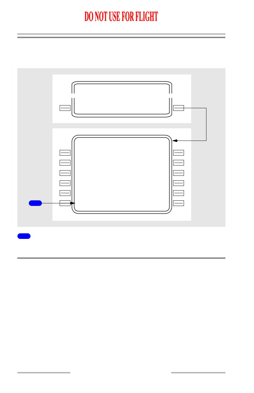
The MAINT BITE INDEX page is available only on the ground and provides
access to data for use by maintenance personnel.
INIT/R EF INDEX
1 / 1
<OFFSE T
MAINT>
MAINT BITE INDEX
1 / 1
<FMC S
ENGINE>
<DFC S
APU>
<A/ T
FQIS>
<ADIR S
<CD S
1
<INDE X
F MC DOWNLOAD>
1
INDEX
Displays the INIT/REF INDEX page.
Navigation Position
[Option - With GPS]
The FMC determines present position from the IRS, GPS, and navigation radios.
The FMC uses its calculated present position to generate lateral steering
commands along the active leg to the active waypoint.
[Option - Dual FMC]
When the FMC Source Select Switch is positioned to NORMAL, the left FMC
becomes primary, however, data from both FMCs is combined to determine a
composite position and velocity for guidance and map displays.
11.31.4
Flight Management, Navigation -
Flight Management System
Operation
Boeing 737 Operations Manual
FMC Position Update
[Option - With GPS]
On the ground, the FMC calculates present position based on GPS data. If GPS
data is not available, the FMC calculates present position based on IRS data.
[Option - FMC U10.2 and later]
If GPS UPDATE is OFF, the FMC updates position to the takeoff runway
threshold when a TO/GA switch is pushed. When making an intersection takeoff,
the intersection data must be entered on the TAKEOFF REF page. If GPS
UPDATE is ON, the TO/GA update is inhibited. GPS UPDATE is on the NAV
OPTIONS page.
[Option - Runway position update via the CDU only]
On the ground prior to takeoff, FMC position update to the takeoff runway
threshold position can be done on the TAKEOFF REF page.
[Option - With GPS]
In flight, the FMC position is continually updated from the GPS, navigation
radios, and IRS. Updating priority is based on the availability of valid data from
the supporting systems.
FMC position updates from navigation sensor positions are used in the following
priority order:
• GPS
• two or more DME stations
• one VOR with a collocated DME
• one localizer and collocated DME
• one localizer.
The station identifiers and frequencies of the selected radio navigation aids are
displayed on the NAV STATUS page 1/2.
FMC logic selects the GPS position as the primary update to the FMC position. If
all GPS data becomes unavailable, the FMC reverts to radio or IRS updating.
The dual frequency-scanning DME radios are automatically tuned by the FMC.
The stations to be tuned are selected based upon the best available signals (in
terms of geometry and strength) for updating the FMC position, unless a specific
station is required by the flight plan. Radio position is determined by the
intersection of two DME arcs.
11.31.5
Flight Management, Navigation -
Flight Management System
Operation
Boeing 737 Operations Manual
If the DME radios fail, or if suitable DME stations are not available, FMC
navigation is based on IRS position information only. The two VHF Nav radios
are used by the FMC for localizer updating during an ILS approach and by the
crew for navigation monitoring.
Note: The FMC is designed to automatically reject unreliable navaid data during
FMC position updating. However, in certain conditions, navaids which are
in error may satisfy the reasonableness criteria and provide the FMC with
an inaccurate radio position. One of the most vulnerable times is when a
radio position update occurs just after takeoff. This is usually manifested
in an abrupt heading correction after engaging LNAV. The position shift
can be seen on the map which will shift the desired track and runway
symbol to a position significantly different from that displayed during
ground roll.
[Option - FMC U10.3 and later]
Note: If the flight crew observes either of these indications, the FMC should be
carefully monitored.
When adequate radio updating is not available, navigation display map mode may
display a shift error. This error results in the displayed position of the airplane,
route, waypoints, and navigation aids shifted from their actual positions.
An across track, undetected map shift may result in the airplane flying a ground
track that is offset from the desired track. An along track, undetected map shift
may result in the flight crew initiating altitude changes earlier or later than desired.
In either case, an undetected map shift may compromise terrain or traffic
separation.
Map shift errors can be detected by comparing the position of the airplane on the
navigation display map mode with data from the ILS, VOR, DME, and ADF
systems.
Navigation Performance
The FMC uses data from the navigation systems to accurately calculate the
position of the airplane. The current FMC position is shown on line 1 of the POS
REF page 2/3.
[Option - With GPS]
The FMC position is derived from a mathematical combination of the positions
determined by the IRS, radio, and GPS systems. It represents the FMC’s estimate
of the actual position of the airplane. Its accuracy varies according to the accuracy
of the other position determining systems.
[Option - FMC U10.4 and later]
Note: If the GPS position update is excessive, GPS updating is suspended until
the GPS position can be determined to be reasonable.
11.31.6
Flight Management, Navigation -
Flight Management System
Operation
Boeing 737 Operations Manual
Actual Navigation Performance (ANP)
Actual navigation performance (ANP) is the FMC’s estimate of the quality of its
position determination. It is shown on POS SHIFT page 3/3 and on RTE LEGS
pages. ANP represents the estimated maximum position error with
95%
probability. That is, the FMC is 95% certain that the airplane’s actual position lies
within a circle with a radius of the ANP value around the FMC position. The lower
the ANP value, the more confident the FMC is of its position estimate.
Required Navigation Performance (RNP)
The FMC supplies a default required navigation performance (RNP) value for
takeoff, en route, oceanic, terminal, and approach phases of flight. RNP can also
be supplied by the Navigation Database or may be entered by the crew. Actual
navigation performance should not exceed RNP.
[Option - FMC U10.3, U10.4 or U10.4A]
If ANP exceeds the RNP value, the UNABLE REQD NAV PERF-RNP message
appears. RNP is shown on POS SHIFT page 3/3 and on RTE LEGS pages.
[Option - FMC U10.5 and later]
If ANP exceeds the RNP value, an amber UNABLE REQD NAV PERF-RNP
message appears on the map display. RNP is shown on RNP PROGRESS page 4/4
and on RTE LEGS pages.
11.31.7