Seat Leon 1M. Service Manual - part 3


  Index      Seat     Seat Leon 1M. Service Manual


Search            copyright infringement  


Content      ..     1      2      3      4      ..


Seat Leon 1M. Service Manual - part 3


-------------------------------------------------------------------------------------------------------------------------------------------------------------
1.32

––––––––––––––––––––––––––––––––––––––––––––––––––––––––––

SEATS AND HEAD RESTRAINTS 

SAFETY FIRST

F

Frro

on

ntt s

se

ea

atts

s

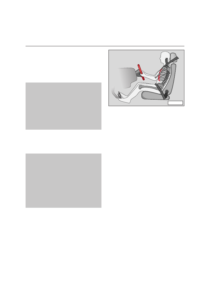
The  correct adjustment of the  seats is
important for:

– reaching the controls safely and quickly.

– relaxed low-fatigue body position.

– m

ma

ax

xiim

mu

um

m  p

prro

otte

ec

cttiio

on

n  ffrro

om

m  tth

he

e  s

se

ea

att

b

be

elltts

s a

an

nd

d tth

he

e A

Aiirr B

Ba

ag

g S

Sy

ys

stte

em

m..

W

Wa

arrn

niin

ng

g

IItt iis

s iim

mp

po

orrtta

an

ntt tto

o m

ma

aiin

ntta

aiin

n a

a d

diis

s--

tta

an

nc

ce

e  o

off  a

att  lle

ea

as

stt  2

25

5  c

cm

m  ffrro

om

m  tth

he

e

s

stte

ee

erriin

ng

g  w

wh

he

ee

ell  o

orr  iin

ns

sttrru

um

me

en

ntt

p

pa

an

ne

ell  s

so

o  tth

ha

att  tth

he

e  ffrro

on

ntt  s

se

ea

att  o

oc

cc

cu

u--

p

pa

an

ntts

s  h

ha

av

ve

e  tth

he

e  b

be

es

stt  p

po

os

ss

siib

blle

e

e

effffe

ec

cttiiv

ve

e  p

prro

otte

ec

cttiio

on

n  iiff  tth

he

e  s

sy

ys

stte

em

m

iis

s  ttrriig

gg

ge

erre

ed

d..  IIn

n  a

ad

dd

diittiio

on

n,,  tth

he

e  ffrro

on

ntt

s

se

ea

atts

s a

an

nd

d tth

he

e h

he

ea

ad

d rre

es

sttrra

aiin

ntts

s m

mu

us

stt

b

be

e a

ad

djju

us

stte

ed

d tto

o tth

he

e b

bo

od

dy

y h

he

eiig

gh

htt..

Consult the "Front seats" chapter for seat
adjustment.  Also  note  on  this page  the
basicadjustment of the driver’s and pas-
senger seats.

W

Wa

arrn

niin

ng

g

N

No

o  iitte

em

ms

s  m

mu

us

stt  b

be

e  k

ke

ep

ptt  iin

n  tth

he

e

ffo

oo

ottw

we

ellll,,  a

as

s  tth

he

es

se

e  c

co

ou

ulld

d  b

bllo

oc

ck

k  tth

he

e

p

pe

ed

da

alls

s iin

n c

ca

as

se

e o

off s

su

ud

dd

de

en

n b

brra

ak

kiin

ng

g..

C

Co

on

ns

se

eq

qu

ue

en

nttlly

y,,  iitt  w

wo

ou

ulld

d  b

be

e  iim

mp

po

os

s--

s

siib

blle

e  tto

o  b

brra

ak

ke

e,,  c

ch

ha

an

ng

ge

e  g

ge

ea

arr  o

orr

a

ac

cc

ce

elle

erra

atte

e..

F

Fe

ee

ett s

sh

ho

ou

ulld

d rre

em

ma

aiin

n iin

n tth

he

e ffo

oo

ottw

we

ellll

w

wh

he

en

n tth

he

e v

ve

eh

hiic

clle

e iis

s m

mo

ov

viin

ng

g,, n

ne

ev

ve

err

rre

es

sttiin

ng

g o

on

n tth

he

e iin

ns

sttrru

um

me

en

ntt p

pa

an

ne

ell o

orr

s

se

ea

atts

s..

D

Drriiv

ve

err’’s

s s

se

ea

att

We  recommend  that you  position  the  dri-
ver’s seat as follows:

– Set the  driver’s seat forwards/back-

wards in such a way that the pedals can
be  fully depressed  with  a  slightly
angled leg.

– Set the backrest in such a way that it is

fully against your back and that you can
reach  the  upper  point of the  steering
wheel with your arms at a slight angle.

F

Frro

on

ntt p

pa

as

ss

se

en

ng

ge

err s

se

ea

att

We recommend that you position the front
passenger seat as follows:

– Backrest in an upright position.

–  Place  the  feet in  the  footwell in  a  com-

fortable position.

– At the same time push the seat back as

far as possible.

B1S-016P

-------------------------------------------------------------------------------------------------------------------------------------------------------------

-------------------------------------------------------------------------------------------------------------------------------------------------------------

SEATS AND HEAD RESTRAINTS 

––––––––––––––––––––––––––––––––––––––––––––––––––––––––––

1.33

SAFETY FIRST

H

He

ea

ad

d rre

es

sttrra

aiin

ntts

s*

*

The  head  restraints are  height adjustable
and  must be  set to  suit the  size  of the
occupant. 

Correctly

adjusted 

head

restraints together  with  the  seat belts
offer effective protection. It is also possi-
ble  to  set the  angle  of the  front head
restraints.

A

Ad

djju

us

sttiin

ng

g h

he

eiig

gh

htt

Grip  sides of head  restraint with  both

hands and pull up or push down.

The  best protection  is obtained  when

the upper edge of the restraint is a

att lle

ea

as

stt

at eye level or higher.

B1S-017P

-------------------------------------------------------------------------------------------------------------------------------------------------------------

-------------------------------------------------------------------------------------------------------------------------------------------------------------

-------------------------------------------------------------------------------------------------------------------------------------------------------------

-------------------------------------------------------------------------------------------------------------------------------------------------------------

INSTRUMENT PANEL

Table . . . . . . . . . . . . . . . . . . . . . . 2.2

Instruments . . . . . . . . . . . . . . . . . 2.5

Warning lamps . . . . . . . . . . . . . 2.13

OPENING AND CLOSING

Keys . . . . . . . . . . . . . . . . . . . . . . 2.23

Keys with remote control* . . . . . 2.24

Electronic immobiliser . . . . . . . . 2.25

Doors . . . . . . . . . . . . . . . . . . . . . 2.26

Central locking* . . . . . . . . . . . . . 2.27

Tailgate . . . . . . . . . . . . . . . . . . . 2.32

Anti-theft alarm system* . . . . . . 2.33

Radio-frequency remote 

control key* . . . . . . . . . . . . . . . . 2.36

Electric windows* . . . . . . . . . . . . 2.39

Sliding/tilting roof* . . . . . . . . . . 2.43

LIGHTS AND VISIBILITY

Switches . . . . . . . . . . . . . . . . . . . 2.45

Sun visors . . . . . . . . . . . . . . . . . 2.48

Indicators and dipped beam 

lever . . . . . . . . . . . . . . . . . . . . . . 2.49

Interior lights . . . . . . . . . . . . . . . 2.50

Windscreen wipers and 

washers . . . . . . . . . . . . . . . . . . . 2.51

Wiper blades . . . . . . . . . . . . . . . 2.53

Rear-view mirrors . . . . . . . . . . . . 2.55

SEATS AND LUGGAGE

COMPARTMENT

Front seats . . . . . . . . . . . . . . . . . 2.58

Head restraints* . . . . . . . . . . . . . 2.62

Armrest* . . . . . . . . . . . . . . . . . . . 2.63

Heated seats* . . . . . . . . . . . . . . 2.64

Adjustable steering column* . . . 2.64

Pedals . . . . . . . . . . . . . . . . . . . . 2.65

Luggage compartment . . . . . . . . 2.65

Rear shelf . . . . . . . . . . . . . . . . . . 2.67

Rear seat . . . . . . . . . . . . . . . . . . 2.68

Roof rack*. . . . . . . . . . . . . . . . . . 2.70

Ashtrays . . . . . . . . . . . . . . . . . . . 2.72

Cigarette lighter/electric socket . 2.73

Stowage box. . . . . . . . . . . . . . . . 2.73

Drink can holder* . . . . . . . . . . . . 2.74 

CLIMATE CONTROL

Heating and ventilation . . . . . . . 2.75

Air conditioning* . . . . . . . . . . . . 2.78

Climatronic* . . . . . . . . . . . . . . . . 2.85

DRIVING

Manual gearbox . . . . . . . . . . . . . 2.90

Automatic gearbox* . . . . . . . . . . 2.90

Handbrake . . . . . . . . . . . . . . . . . 2.96

Ignition lock . . . . . . . . . . . . . . . . 2.97

Starting the engine . . . . . . . . . . 2.98

Stopping the engine. . . . . . . . . 2.100

Cruise control system* . . . . . . . 2.101

HANDLING INSTRUCTIONS 

–––––––––––––––––––––––––––––––––––––––––––––––––––––––––––––––––

2.1

INDEX

-------------------------------------------------------------------------------------------------------------------------------------------------------------

-------------------------------------------------------------------------------------------------------------------------------------------------------------

2.2

–––––––––––––––––––––––––––––––––––––––––––––––––––––––––––––––––––––––

INSTRUMENT PANEL

HANDLING INSTRUCTIONS

T

Ta

ab

blle

e

1

2

3

4

5

6

19

20

21

22

23

24

25

26

27

28

-------------------------------------------------------------------------------------------------------------------------------------------------------------

-------------------------------------------------------------------------------------------------------------------------------------------------------------

INSTRUMENT PANEL 

–––––––––––––––––––––––––––––––––––––––––––––––––––––––––––––––––––––––

2.3

HANDLING INSTRUCTIONS

5

7

8

9

10

11

12

13

14

15

16

17

18

LEO-001A

-------------------------------------------------------------------------------------------------------------------------------------------------------------

-------------------------------------------------------------------------------------------------------------------------------------------------------------

Position

Page

1 – Door handle ........................... 2.26

2 – Knurled wheel for instrument

lighting*................................. 2.46

3 – Knurled wheel for light range 

adjustment* ........................... 2.46

4 – Light switch ............................ 2.45

5 – Air vents................ 2.75/2.80/2.85

6 – Indicator/dipped beam lever... 2.49

7 – Heated rear window switch ..... 2.46

8 – Hazard warning light switch .... 2.47

9 – Knurled wheel for left

seat heating*/
Drink can holder ..............2.64/2.74

10 – Knurled wheel for right

seat heating*/
Drink can holder ..............2.64/2.74

11 – Passenger Air Bag* ................. 1.16

12 – Glove compartment/ 

stowage box ........................... 2.73

13 – Stowage box........................... 2.73

14 – Radio/Radio housing

1)

*

Radio navigation system

1)

* ..... 3.85

15 – Controls for:

– Heating/ventilation ............. 2.76
– Air conditioning* ................. 2.79
– Climatronic* ........................ 2.86

16 – Automatic*/Manual gear lever .. 2.90

17 – Ashtray/ lighter.............. 2.72/2.73

18 – Pedals .................................... 2.65

19 – Windshield washer/wipers

lever/Multifunction 
indicator* ........................ 2.51/2.8

Position

Page

20 – Steering and ignition lock .....

2.97

21 – Driver’s Air Bag/Horn .............. 1.16

22 – Steering column adjustment

lever* ..................................... 2.64

23 – On board literature 

compartment .......................... 2.74

24 – Instrument and warning lamps

panel ..................................... 2.13

25 – Bonnet release lever ............... 3.35

26 – Electric wing mirror 

adjustment lever* ................... 2.55

27 – Central locking button* ........... 2.29

28 – Electric window controls*  ....... 2.39

Some  of the  equipment above-men-

tioned  is only installed  on  certain  model
versions or comes as an option.

Controls on  right hand  drive  models

may slightly vary from left-hand drive ver-
sions.  Nevertheless both  versions are  fit-
ted with the very same indicator signs.

1)

An  additional instructions manual is delivered
for vehicles with a navigation system or factory-
fitted radio. If the radio is subsequently fitted,
follow  indications in  the  "Accessories,  modifi-
cations and replacement of parts" chapter.

HANDLING INSTRUCTIONS

2.4

–––––––––––––––––––––––––––––––––––––––––––––––––––––––––––––––––––––––

INSTRUMENT PANEL

-------------------------------------------------------------------------------------------------------------------------------------------------------------

-------------------------------------------------------------------------------------------------------------------------------------------------------------

INSTRUMENT PANEL 

––––––––––––––––––––––––––––––––––––––––––––––––––––––––––––––––––––––

2.5

HANDLING INSTRUCTIONS

IIn

ns

sttrru

um

me

en

ntts

s

In  some  model versions or  in  certain
countries, it is possible to insert the igni-
tion  key and  have  the  dash  panel lights
go  on  without switching  the  engine  on.
This function  is independent of the  vehi-
cle's light connections.

The  arrangement of the  instruments
depends on the model and the engine fit-
ted.

Page

1 – Revolutions counter* .................. 2.5

2 – Coolant temperature ................... 2.6

3 – Fuel gauge.................................. 2.7

4 – Speedometer .............................. 2.7

5 – Digital clock*...............................2.7

Outside temperature indicator* .....2.7

Multifunction indicator* ..............2.8

6 – Selector lever position display*. 2.11

7 – Mileage clock with Service 

interval indicator* ............ 2.11/2.12

1

1 –

– R

Re

ev

vo

ollu

uttiio

on

ns

s c

co

ou

un

ntte

err*

*

O

On

n  n

no

o  a

ac

cc

co

ou

un

ntt  m

mu

us

stt  tth

he

e  rre

ev

vo

ollu

uttiio

on

ns

s

c

co

ou

un

ntte

err  n

ne

ee

ed

dlle

e  m

mo

ov

ve

e  iin

ntto

o  tth

he

e  rre

ed

d

z

zo

on

ne

e o

off tth

he

e s

sc

ca

alle

e..

C

Ch

ha

an

ng

giin

ng

g  u

up

p  iin

n  g

go

oo

od

d  ttiim

me

e  h

he

ellp

ps

s

tto

o  s

sa

av

ve

e  ffu

ue

ell  a

an

nd

d  k

ke

ee

ep

p  tth

he

e  n

no

oiis

se

e

d

do

ow

wn

n..

Change  down  a  gear  at the  latest when
the engine turn over is no longer smooth.

Avoid  high  engine  revolutions during  the
running-in period.

2

1

3

4

5

6

7

8

0

Rpm x 1000

20

0

Km/h

40

60

80

100

140

180

220

260

10

30

50

70

90

120

160

200

240

km

60

90

120

0

1/2

1/1

!

1

E P C

5

1

2

3

4

7

P R


N


D 3 2 1

6

LEO-002

-------------------------------------------------------------------------------------------------------------------------------------------------------------

-------------------------------------------------------------------------------------------------------------------------------------------------------------

2

2 –

– C

Co

oo

olla

an

ntt tte

em

mp

pe

erra

attu

urre

e

The  gauge  starts to  work when  the  igni-
tion is switched on.

When  the  ignition  is switched  on  the
warning  lamp  (c

c)  flashes for  a  few  sec-

onds as a functional check.

a

a –

– C

Co

olld

d

Avoid  high  engine  speeds and  do  not
work engine too hard yet.

b

b –

– N

No

orrm

ma

all

When  the  vehicle  is driven  normally the
needle  should  settle  down  in  the  central
zone.

When  engine  is working  hard  and  the
ambient temperature  is high,  the  needle
may move a long way up.

T

Th

hiis

s  iis

s  n

no

ott  s

se

erriio

ou

us

s  a

as

s  llo

on

ng

g  a

as

s  tth

he

e

w

wa

arrn

niin

ng

g lla

am

mp

p ((c

c)) d

do

oe

es

s n

no

ott fflla

as

sh

h..

c

c –

– W

Wa

arrn

niin

ng

g lla

am

mp

p

If the lamp flashes and a tone is heard at
the  same  time  when  driving,  first check
the coolant temperature being displayed.

If the  needle  is in  the  normal zone,
coolant should be added as soon as pos-
sible.  See  the  chapter  on  “Cooling  sys-
tem”.

If the needle is in the right half of the indi-
cator, the coolant temperature is too high.
IIn

n  tth

hiis

s  c

ca

as

se

e,,  p

pu

ullll  o

ov

ve

err,,  s

sw

wiittc

ch

h  tth

he

e

e

en

ng

giin

ne

e o

offff,, w

wa

aiitt u

un

nttiill iitt c

co

oo

olls

s and then

look for the cause of the problem. See the
chapter on “Cooling system”.

W

Wa

arrn

niin

ng

g

N

No

otte

e w

wa

arrn

niin

ng

gs

s iin

n "

"C

Co

oo

olliin

ng

g s

sy

ys

stte

em

m"

"

c

ch

ha

ap

ptte

err..

A

Ad

dd

diittiio

on

na

all  lliig

gh

htts

s  iin

n  ffrro

on

ntt  o

off  tth

he

e  c

co

oo

oll--

iin

ng

g  a

aiirr  iin

ntta

ak

ke

e  iin

ntte

errffe

erre

e  w

wiitth

h  tth

he

e  ffllo

ow

w

o

off  c

co

oo

olliin

ng

g  a

aiirr..  A

Att  h

hiig

gh

h  a

am

mb

biie

en

ntt  tte

em

m--

p

pe

erra

attu

urre

es

s  a

an

nd

d  ffu

ullll  tth

hrro

ottttlle

e  tth

he

erre

e  iis

s  a

a

d

da

an

ng

ge

err tth

ha

att tth

he

e e

en

ng

giin

ne

e w

wiillll tth

he

en

n o

ov

ve

err--

h

he

ea

att..

2.6

––––––––––––––––––––––––––––––––––––––––––––––––––––––––––––––––––––––

INSTRUMENT PANEL

HANDLING INSTRUCTIONS

6

60

90

120

0

1

c

a

b

IB9-035

-------------------------------------------------------------------------------------------------------------------------------------------------------------

-------------------------------------------------------------------------------------------------------------------------------------------------------------

INSTRUMENT PANEL 

––––––––––––––––––––––––––––––––––––––––––––––––––––––––––––––––––––––

2.7

HANDLING INSTRUCTIONS

3

3 –

– F

Fu

ue

ell g

ga

au

ug

ge

e

When  the  ignition  is switched  on,  the
warning  light lights up  as a  functional
check.

The tank holds about 55 litres.

When the needle moves to the red reserve
zone,  warning  light d

d lights up  at the

same time that an acoustic warning signal
is produced;  this means that approxi-
mately 7 litres of fuel remain.

4

4 –

– S

Sp

pe

ee

ed

do

om

me

ette

err

The  speedometer  is fitted  with  a  digital
mileage clock and a trip mileage clock, as
well as a service interval indicator*.

During  the  running  in  period  you  must
note  the  instructions in  the  chapter  "The
first 1,500 km – and afterwards".

5

5 –

– D

Diig

giitta

all c

cllo

oc

ck

k*

*

The  digital clock is set by turning  a  knob
that is on  the  bottom  right next to  the
speedometer.

The hours are set by turning the button

anti-clockwise  until it stops.  By turning
the  knob  once,  you  move  forward  one
hour.  By turning  and  holding  the  knob,
the hours move forward continuously.

The minutes are set by turning the but-

ton clockwise until it stops. By turning the
knob once, you move forward one minute.
By turning and holding the knob, the min-
utes move forward continuously.

The  knob  can  be  used  to  set the  clock to
the exact second.

Turn the knob to the right until the time

is set to  exactly one  minute  before  the
required time.

Turn  the  button  to  the  right just as the

seconds indicator  of an  accurately set
clock shows one full minute.

Turning  the  button  to  the  left sets the

clock to the required arrow.

5

5 –

– O

Ou

utts

siid

de

e tte

em

mp

pe

erra

attu

urre

e iin

nd

diic

ca

atto

orr*

*

The  outside  temperature  is displayed
when the ignition is on. 

At temperatures from  +5  °C to  –5  °C,  a
snowflake symbol is displayed along with
the temperature.

T

Th

he

e  s

sn

no

ow

wfflla

ak

ke

e  s

sy

ym

mb

bo

oll  iis

s  tto

o  w

wa

arrn

n  tth

he

e

d

drriiv

ve

err tto

o tta

ak

ke

e e

ex

xttrra

a c

ca

arre

e w

wh

he

en

n tth

he

erre

e iis

s

a

a rriis

sk

k o

off iic

ce

e ffo

orrm

miin

ng

g o

on

n tth

he

e rro

oa

ad

d..

When  the  vehicle  is stationary or  travel-
ling  at very low  speeds,  the  temperature
displayed may be slightly higher than the
actual outside  temperature  as a  result of
radiant heat from the engine.

60

50

120

0

1/2

1/1

1

d

IB9-036

-------------------------------------------------------------------------------------------------------------------------------------------------------------

-------------------------------------------------------------------------------------------------------------------------------------------------------------

2.8

––––––––––––––––––––––––––––––––––––––––––––––––––––––––––––––––––––––

INSTRUMENT PANEL

HANDLING INSTRUCTIONS

5

5 –

– M

Mu

ullttiiffu

un

nc

cttiio

on

n iin

nd

diic

ca

atto

orr*

*

The multifunction indicator includes:

Time

Driving time

Average speed

Distance covered

Autonomy

Average fuel consumption

Current consumption

The  function  selector  and  the  reset key
are located in the windshield wiper arm.

With the ignition switched on, repeatedly
press the upper or lower part of the func-
tion selector and the functions will appear
one after the other.

When  the  ignition  is switched  on,  the
function  which  was selected  before
switching  off the  ignition  will be  acti-
vated,  unless the  ice  warning  symbol
appears with  outside  temperature  of
+ 5°C and – 5°C.

If the  vehicle  battery is disconnected,  all
stored values will be deleted.

B8L-103

6

5

7

8

10.0

3

2

1

0

rpm x 1000

l/100 km

LEO-003

-------------------------------------------------------------------------------------------------------------------------------------------------------------

-------------------------------------------------------------------------------------------------------------------------------------------------------------

INSTRUMENT PANEL 

––––––––––––––––––––––––––––––––––––––––––––––––––––––––––––––––––––––

2.9

HANDLING INSTRUCTIONS

M

Me

em

mo

orry

y

The  system  is equipped  with  two  memo-
ries which function automatically.

A

A p

pa

arrttiia

all rro

ou

utte

e m

me

em

mo

orry

y ((M

Mu

ullttiiffu

un

nc

cttiio

on

n

IIn

nd

diic

ca

atto

orr  1

1)) gathers the  following  data

between  switching  the  ignition  on  and
off:

Driving  time,  distance  covered  and  used
fuel.

Speed and average fuel consumption are
calculated using the above information.

If driving  is resumed  within  two  hours
from  switching  off the  ignition,  the  data
collected  while  driving  is included  in  the
calculation.  If driving  is not resumed
within two hours, the memory is automat-
ically deleted.

A

A  tto

otta

all  rro

ou

utte

e  m

me

em

mo

orry

y  ((M

Mu

ullttiiffu

un

nc

cttiio

on

n

IIn

nd

diic

ca

atto

orr  2

2)) collects driving  data  from

any number of partial routes up to a total
of 100  driving  hours,  10,000  kilometres
and  a  fuel consumption  of 1,500  litres.
This data  is used  to  calculate  average
consumption  and  speed  from  all partial
routes. 

If some  of the  before  mentioned  data  is
exceeded, the memory is deleted and the
calculation  starts over.  Contrary to  the
partial route  memory,  this memory is not
deleted  when  driving  is interrupted  for
more than two hours.

C

Co

on

ns

su

ulltt m

me

em

mo

orry

y

To  consult data  select the  memory by
pressing  the  "R

Re

es

se

ett"  key for  <  2  seconds

and from one of the specific Multifunction
Indicator 1 or 2 functions.

– Partial route  memory -  Multifunction

Indicator 1

– Total route  memory -  Multifunction

Indicator 2

The following data can be displayed:

Driving time

Distance covered

Average speed

Average fuel consumption

D

De

elle

ette

e m

me

em

mo

orry

y

Memory data  is reset by pressing  the
"Reset" key for > 2 seconds. 

-------------------------------------------------------------------------------------------------------------------------------------------------------------

-------------------------------------------------------------------------------------------------------------------------------------------------------------

2.10

–––––––––––––––––––––––––––––––––––––––––––––––––––––––––––––––––––––

INSTRUMENT PANEL

HANDLING INSTRUCTIONS

IIn

nd

diic

ca

attiio

on

ns

s o

on

n s

sc

crre

ee

en

n

The  last selected  item  will be  displayed
when the ignition is switched on.

O

Ou

utts

siid

de

e tte

em

mp

pe

erra

attu

urre

e

°°C

C

The correct outside temperature takes five
minutes to  be  displayed.  When  the  vehi-
cle  is stationary or  moving  slowly,  the
indicated  temperature  may be  slightly
higher  than  the  real outside  temperature
due to the engine heat.

W

Wa

arrn

niin

ng

g

IIn

n tte

em

mp

pe

erra

attu

urre

es

s b

be

ettw

we

ee

en

n +

+5

°C

C a

an

nd

d

–5

°C

C  tth

he

e  iic

ce

e  w

wa

arrn

niin

ng

g  s

sy

ym

mb

bo

oll  iis

s

d

diis

sp

plla

ay

ye

ed

d n

ne

ex

xtt tto

o tth

he

e o

ou

utts

siid

de

e tte

em

m--

p

pe

erra

attu

urre

e  iin

nd

diic

ca

attiio

on

n..  IIn

n  c

ca

as

se

e  tth

hiis

s

ffu

un

nc

cttiio

on

n  w

wa

as

s  n

no

ott  s

se

elle

ec

ctte

ed

d,,  tth

he

e

s

sc

crre

ee

en

n  w

wo

ou

ulld

d  a

au

utto

om

ma

attiic

ca

alllly

y  d

diis

s--

p

plla

ay

y iitt..

T

Tiim

me

e

The  time  is displayed  even  if the  ignition
is switched  off.  The  clock is set with  the
right rotary knob  below  the  speedometer
(see  "digital clock"  in  the  Instructions
Manual).

D

Drriiv

viin

ng

g ttiim

me

e

M

Mu

ullttiiffu

un

nc

cttiio

on

n IIn

nd

diic

ca

atto

orr 1

1 – Driving time

from  switching  on  the  ignition  or  from
resetting  memory (see  "special route
memory").

M

Mu

ullttiiffu

un

nc

cttiio

on

n  IIn

nd

diic

ca

atto

orr  2

2  –  Total dri-

ving time of all partial routes (see "mem-
ory of total route").

The maximum value displayed with either
selector position is 99 hours and 59 min-
utes. If this value is exceeded, the display
is reset.

A

Av

ve

erra

ag

ge

e s

sp

pe

ee

ed

d

Ø

Ø k

km

m/

/h

h

The  same  applies to  "average  speed"  as
to "average fuel consumption".

D

Diis

stta

an

nc

ce

e c

co

ov

ve

erre

ed

d

K

Km

m

The same which applies to "distance cov-
ered"  applies to  "driving  time"  (see
below). The maximum displayed distance
is 9,999 km.

A

Au

utto

on

no

om

my

y

K

Km

m

This function indicates the distance which
the  vehicle  can  drive  maintaining  the
same driving style.

Fuel calculation  is based  on  the  average
fuel consumption  during  the  last 50  kilo-
meters.

After  resetting  the  fuel display (i.e.  after
disconnecting  the  battery)  the  real fuel
range  will be  displayed  after  approxi-
mately 50 kilometers).

-------------------------------------------------------------------------------------------------------------------------------------------------------------

-------------------------------------------------------------------------------------------------------------------------------------------------------------

INSTRUMENT PANEL 

–––––––––––––––––––––––––––––––––––––––––––––––––––––––––––––––––––––

2.11

HANDLING INSTRUCTIONS

A

Av

ve

erra

ag

ge

e ffu

ue

ell 

c

co

on

ns

su

um

mp

pttiio

on

n

Ø

Ø ll/

/1

10

00

0 k

km

m

Indicates the  average  fuel consumption,
not the consumption at the moment.

After  switching  on  the  ignition  or  after
deleting  the  corresponding  memory,  the
average  fuel consumption  is displayed
after  having  driven  approximately 300
meters. Until that moment, the screen will
display lines instead  of the  function. The
figure is updated every 5 seconds.

M

Mu

ullttiiffu

un

nc

cttiio

on

n  IIn

nd

diic

ca

atto

orr  1

1 –  indicates

the  average  fuel consumption  of the  par-
tial trip.

M

Mu

ullttiiffu

un

nc

cttiio

on

n  IIn

nd

diic

ca

atto

orr  2

2 –  indicates

the average fuel consumption of all of the
partial trips (see  also  "memory of total
route").

N

No

otte

e

The quantity of fuel which has been used
is not indicated.

C

Cu

urrrre

en

ntt c

co

on

ns

su

um

mp

pttiio

on

n

ll/

/1

10

00

0 k

km

m

Indicates the  current consumption  in
l/100 km.

The consumption is calculated in intervals
of 2  seconds.  When  the  vehicle  is
stopped, the consumption is indicated in
l/h.

6

6 –

– S

Se

elle

ec

ctto

orr lle

ev

ve

err p

po

os

siittiio

on

n d

diis

sp

plla

ay

y*

*

The  position  of the  automatic gearbox
selector  lever  is indicated  in  the  display.
See "Automatic gearbox" chapter.

7

7 –

– M

Miille

ea

ag

ge

e c

cllo

oc

ck

k/

/ T

Trriip

p m

miille

ea

ag

ge

e

The  upper  counter  registers the  total dis-
tance  driven  and  the  lower  one  the  short
trips.

The  last figure  of the  lower  counter  indi-
cates 100 m.

The  trip  mileage  can  be  put back to  zero
by pressing  the  reset knob  next to  the
speedometer (partial mileage clock).

-------------------------------------------------------------------------------------------------------------------------------------------------------------

-------------------------------------------------------------------------------------------------------------------------------------------------------------

2.12

–––––––––––––––––––––––––––––––––––––––––––––––––––––––––––––––––––––

INSTRUMENT PANEL

HANDLING INSTRUCTIONS

7

7 –

– S

Se

errv

viic

ce

e iin

ntte

errv

va

all iin

nd

diic

ca

atto

orr*

*

If a service is due, the word "Service" will
flash  for  about 20  seconds when  the
engine  is switched  on,  the  vehicle  is not
moving  and  the  mileage  clock reset but-
ton is not touched.

The  deadline  for  any service  will be  dis-
played 3,000 km in advance.

IIn

ntte

errm

miitttte

en

ntt  s

se

errv

viic

ce

e*

*  ffo

orr  2

20

0  s

se

ec

c--

o

on

nd

ds

s..  Indicates that the  time  for  a  new

service has elapsed.

S

Se

errv

viic

ce

e  K

Km

m  3

3,,0

00

00

0*

*  ffo

orr  2

20

0  s

se

ec

co

on

nd

ds

s..

Indicates that the  next service  is due  in
3,000  km.  Every 100  km  the  number  of
km will decrease by 100 km up to the indi-
cation "Service".

A

Afftte

err tth

he

e s

se

errv

viic

ce

e h

ha

as

s b

be

ee

en

n p

pe

errffo

orrm

me

ed

d

tth

he

e d

diis

sp

plla

ay

y n

ne

ee

ed

ds

s tto

o b

be

e rre

es

se

ett..

The  display will be  reset by a  Technical
Service Centre as follows:

Switch ignition off

Keep the odometer reset button next to

the speedometer pressed down.

Without releasing  the  aforementioned

button, switch the ignition on. “S

SE

ER

RV

VIIC

CE

E”

will then appear on the display. Next, turn
the  button  toward  the  right,  for  at least
one second.

The  display automatically returns to

normal mode (total km + partial km), and
in this way, the system remains activated
for the oil change service.

N

No

otte

es

s

D

Do

o n

no

ott z

ze

erro

o tth

he

e d

diis

sp

plla

ay

y b

be

ettw

we

ee

en

n tth

he

e

s

se

errv

viic

ce

e  iin

ntte

errv

va

alls

s..  O

Otth

he

errw

wiis

se

e  a

an

n  iin

nc

co

orr--

rre

ec

ctt rre

ea

ad

diin

ng

g w

wiillll a

ap

pp

pe

ea

arr..

IIff  tth

he

e  b

ba

atttte

erry

y  s

sh

ho

ou

ulld

d  b

be

e  d

diis

sc

co

on

n--

n

ne

ec

ctte

ed

d,, tth

he

e s

se

errv

viic

ce

e iin

nd

diic

ca

atto

orr iin

nffo

orrm

ma

a--

ttiio

on

n w

wiillll b

be

e rre

etta

aiin

ne

ed

d..

IIff  tth

he

e  iin

ns

sttrru

um

me

en

ntt  p

pa

an

ne

ell  c

ch

ha

an

ng

ge

es

s

d

du

ue

e tto

o rre

ep

pa

aiirr,, tth

he

e s

se

errv

viic

ce

e iin

ntte

errv

va

all d

diis

s--

p

plla

ay

y  m

mu

us

stt  b

be

e  rre

es

se

ett..  T

Th

hiis

s  s

sh

ho

ou

ulld

d  b

be

e

c

ca

arrrriie

ed

d  o

ou

utt  b

by

y  a

a  T

Te

ec

ch

hn

niic

ca

all  S

Se

errv

viic

ce

e

C

Ce

en

nttrre

e..  IIff  tth

he

e  iin

nd

diic

ca

atto

orr  iis

s  n

no

ott  rre

ep

prro

o--

g

grra

am

mm

me

ed

d,,  tth

he

e  s

se

errv

viic

ce

e  w

wo

orrk

k  m

mu

us

stt  b

be

e

d

do

on

ne

iin

a

ac

cc

co

orrd

da

an

nc

ce

w

wiitth

tth

he

e

M

Ma

aiin

ntte

en

na

an

nc

ce

e a

an

nd

d IIn

ns

sp

pe

ec

cttiio

on

n P

Plla

an

n a

an

nd

d

n

no

ott  tth

he

e  s

se

errv

viic

ce

e  iin

ntte

errv

va

all  iin

nd

diic

ca

atto

orr..

O

On

nlly

y  a

afftte

err  a

a  s

se

errv

viic

ce

e  h

ha

as

s  b

be

ee

en

n  c

ca

arrrriie

ed

d

o

ou

utt  a

an

nd

d  tth

he

e  iin

nd

diic

ca

atto

orr  h

ha

as

s  b

be

ee

en

n  rre

es

se

ett

w

wiillll  tth

he

e  s

se

errv

viic

ce

e  iin

ntte

errv

va

all  iin

nd

diic

ca

atto

orr

rre

eg

ga

aiin

n iitts

s v

va

alliid

diitty

y..

F

Fa

aiillu

urre

e iin

nd

diic

ca

atto

orr

If a  failure  occurs,  "FAIL"  would  appear
either on the instrument panel or the trip
meter. The defect should be repaired by a
Technical Service Centre as soon as possi-
ble.

-------------------------------------------------------------------------------------------------------------------------------------------------------------

-------------------------------------------------------------------------------------------------------------------------------------------------------------

INSTRUMENT PANEL

––––––––––––––––––––––––––––––––––––––––––––––––––––––––––––––––––––––

2.13

HANDLING INSTRUCTIONS

W

Wa

arrn

niin

ng

g lla

am

mp

ps

s

The layout of the warning lamps depends
on  the  model version  and  engine  fitted.
The  symbols shown  here  are  also  on  the
actual warning lamps.

Page

1 – Indicators ..................................2.15

2 – Coolant temperature/level* ........2.15

3 – Trailer indicators* ......................2.16

4 – Fuel level* .................................2.16

5 – Main beam ................................2.16

6 – Warning lamps display screen  ...2.16

7 – Upper display: 

Selector lever position display* .2.16

2

1

3

4

5

6

7

8

0

Rpm x 1000

20

0

Km/h

40

60

80

100

140

180

220

260

10

30

50

70

90

120

160

200

240

km

60

90

120

0

1/2

1/1

1

!

E P C

P R


N


D 3 2 1

0 04

3647

0.0

5

1

2

3

4

1

6

7

LEO-004

-------------------------------------------------------------------------------------------------------------------------------------------------------------


Content      ..     1      2      3      4      ..