Haima S5 1.5T. A/C, Restraint System, Body Accessories, Electrical System. Manual - part 4
Airbags and Restraint System 3B-29
Checking the SST release tool).
2. Park the vehicle in an open capacious area and
prevent the doors and windows from being
closed by the strong breeze.
3. Turn the ignition switch to the LOCK position.
4. Remove the negative cable of the battery and
wait for at least 1min.
5. Release the driver side airbag module, the front
passenger side airbag module, the side airbag
module or the pretensioner seat belt according
to the appropriate procedure.
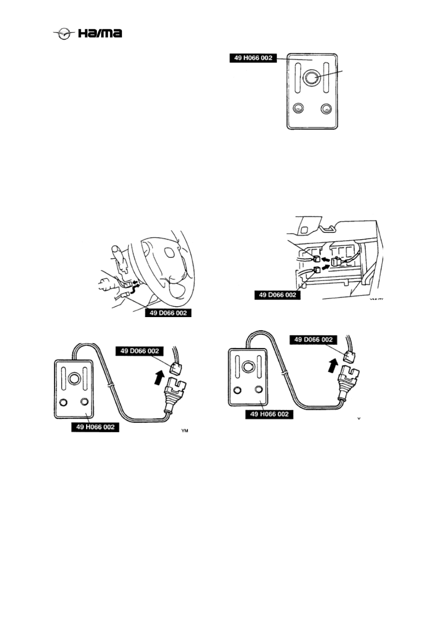
Driver side airbag module
1. Remove the steering column cover plate.
2. Disconnect the clock spring connector.
3. Connect the SST wiring harness with the clock
spring, as shown in the figure.
4. Connect the SST release tool with the SST
wiring harness.
5. Connect the red and black clips of the SST
release tool respectively with the positive and
negative terminals of the battery.
6. Ensure the red lamp on the SST release tool
comes on.
7. Ensure all persons are at least 6m {20 ft } away
from the vehicle.
8. Press the trigger switch on the SST release tool
to make the driver side airbag module released.
Front passenger side airbag module
1. Remove the glove box.
2. Disconnect the front passenger side airbag
module connector.
3. Connect the SST wiring harness with the front
passenger side airbag module, as shown in the
figure.
4. Connect the SST release tool with the SST
wiring harness.
5. Connect the red and black clips of the SST
release tool respectively with the positive and
negative terminals of the battery.
6. Ensure the red lamp on the SST release tool
comes on.
7. Ensure all persons are at least 6m {20 ft } away
from the vehicle.
8. Press the trigger switch on the SST release tool
to make the front passenger side airbag module
released.
Trigger switch
Front passenger
side airbag
module connector
Clock spring
connector