Haima S5 1.5T. A/C, Restraint System, Body Accessories, Electrical System. Manual - part 5


  Index      Haima     Haima S5 1.5T. A/C, Restraint System, Body Accessories, Electrical System. Service Manual


Search            copyright infringement  


Content      ..     3      4      5      6     ..


Haima S5 1.5T. A/C, Restraint System, Body Accessories, Electrical System. Manual - part 5


Body and Accessories 3C-10 


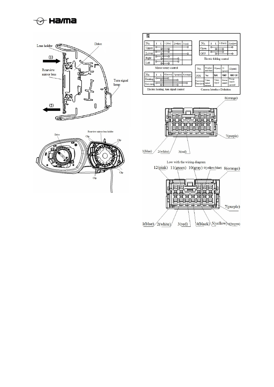
Removing the electric outside rearview 
mirror  

1.  Wear gloves and goggles. 

2.  Remove the outside rearview mirror assembly. 

(Refer to Removing the Mirror Assembly) 

3.  Remove the outside rearview mirror housing. 

4.  Remove the screw, loosen the harness port 

and remove the turn signal lamp.  

5.  Perform the installation in reverse order of the 

removal. 

Checking the electric outside rearview 
mirror  

1. Disconnect the connector of the electric outside 

rearview mirror. (Refer to the 
Removal/Installation of Electric Outside 
Rearview Mirrors) 

2. Apply the battery’s positive voltage to the 

electric outside rearview mirror to check its 
operation. 


3. If it does not comply with the specified, replace 

the electric outside rearview mirror. 


Removal/Installation of Electric Outside 
Rearview Mirror Switch 

1.  Disconnect the negative cable of the battery. 

2.  Disconnect the power mirror switch connection 

joints. 

3. Remove the left panel on the left. 

4. The installation of the switch on the front panel 

can be removed buckle switch a little harder to 
break apart.  

5. Perform the installation in reverse order of the 

removal.  

-------------------------------------------------------------------------------------------------------------------------------------------------------------


Body and Accessories 3C-11 


Checking the electric outside rearview 
mirror switch 

1.  Remove the electric outside rearview mirror 

switch. (Refer to the Removal/Installation of 
Electric Outside Rearview Mirror Switch) 

2.  Use an ohmmeter to check the continuity 

between two pins of the electric outside 
rearview mirror.  


Inside Rearview Mirror  

Removing the Inside Rearview mirror 

1.  Insert a flat-end screwdriver wrapped with 

adhesive tape between the Inside Rearview 
mirror and the pedestal.  

2.  Push the pedestal pin and remove the 

rearview mirror. 


Installing the Inside Rearview mirror 

●  Insert the Inside Rearview mirror into the 

pedestal.  


Removing the rearview mirror pedestal 

1.  Remove the rearview mirror. 

2.  Wrap both ends of the string on the handle.  

Notice: 

●  A complete piano string should be adopted to 

prevent it from being fractured when cutting 
the sealant.  

3.  Saw the sealant and remove the pedestal. 

Make the saw elongated to have the sawing 
points evenly distributed on each section of 
the SST (piano string), to protect the tool 
from being fractured.  


Installing the rearview mirror pedestal 

1.  Use a blade to remove the original sealant 

fully. 

Inside Rearview mirror 

Pedestal 

Inside Rearview mirror 

Pedestal 

Pedestal 

Pedestal pin 

-------------------------------------------------------------------------------------------------------------------------------------------------------------


Body and Accessories 3C-12 


2.  Clean the ceramic membrane on the pedestal 

the glass and remove the grease from it. 

Caution: 

●  The junction surface should be kept free from 

any greasy dirt and dust. Don’t touch the 
prime paint surface, or else the bonding effect 
may be impaired. 

3.  Apply the prime paint on the junction position 

between the pedestal and the glass. Only the 
special prime paint for glass can be applied on 
the glass and only the special prime paint for 
body can be applied on the pedestal. Let the 
paint dry for about 30min.  

4.  Apply the repair sealant 3.0mm{0.12in}thick 

on the pedestal. 


5.  Put the pedestal on the center of the ceramic 

coating and then press it onto the glass. 


Temperature 

Surface 

hardening time 

Interval required 

before the vehicle 

can be used 

5 {41 }


About 1.5h 

About 12h 

20 {68 }


About 1h 

About 4h 

35 {95 }

  About 10min 

About 2h 

6.  Clean the residual repair sealant with the 

unleaded gasoline.  

Sealing Material Hardening Time 


Temperature 

Surface 

hardening time 

Interval required 

before the vehicle 

can be used 

5 {41 }

About 1.5h 

About 12h 

20 {68 }

About 1h 

About 4h 

35 {95 }

About 10min 

About 2h 

7.  Install the Inside Rearview mirror. 

Rear Window Defroster 

Checking the heating wire 

1.  Turn the ignition switch to the ON position. 

2.  Turn on the rear window defroster switch.  

Caution: 

●  Making the test terminal of the circuit tester 

contact directly with the heating wire of the 
rear window defroster may possibly damage 
the heating wire; therefore, please wrap the 
test terminal with the aluminum foil and make 
the aluminum foil contact with the heating 
wire for testing.  


3.  Connect the positive pole (+) of the voltmeter 

to the negative pole of the heating wire and 
make the negative pole (-) grounded.  

4.  Slide the positive test terminal slowly from 

the positive side to the negative side and 
check the voltage for the corresponding drop.  


Measuring section

Voltage (reference value) 

(1)→(2) About 

12V→About 0V 

Ceramic coating 

Pedestal

Pedestal 

Rubber hose 

Sealant 

Circuit tester probe

Heating wire

Aluminum foil

Press

-------------------------------------------------------------------------------------------------------------------------------------------------------------


Body and Accessories 3C-13 


5.  If it is incorrect or the voltage change is too 

fast, there must be some problem in the 
heating wire. Replace the heating wire.  

Repairing the heating wire 

1.  Clean the damaged part of the heating wire 

with the unleaded gasoline. 

2.  Stick the adhesive tape on the top and bottom 

of the damaged section of the heating wire.  


3.  Use a brush or marker pen to apply the 

aluminum powder or similar coating on the 
heating wire for repair.  

4.  In about 2~3min, remove the adhesive tape 

carefully and don’t touch the repaired part. 

Caution: 

● 

Don’t operate the rear defroster until the paint 
is dry; otherwise, fault may occur.  

5.  Use a heat blower to heat it up continuously 

for 30min to the temperature of 150℃{302℉} 
or let the paint get fully dry under the 
temperature of 25℃{77℉} for 24h. 

Removal/Installation of Rear Window 
Defroster Relay 

1.  Disconnect the negative cable of the battery. 

2.  Remove the front side trim plate at the driver 

side.  

3.  Disconnect the rear window defroster relay 

connector.  


4.  Slide the rear window defroster relay forward 

and remove it. 

5.  Perform the installation in reverse order of the 

removal. 

Checking the rear window defroster relay 

1.  Remove the rear window defroster relay. 

(Refer to the Removal/Installation of Rear 
Window Defroster Relay) 

2.  Use an ohmmeter to check the continuity 

between the pins of the rear window defroster 
relay.  


3.  If it does not comply with the specified, 

replace rear window defroster relay. 

Positive side

Negative side

Rear window 
defroster relay 

Rear window 
defroster relay 
connector 

Adhesive tap 

Broken heating wire 

Part to be repaired 

Continuity 

Pin 

Switch position

-------------------------------------------------------------------------------------------------------------------------------------------------------------


Body and Accessories 3C-14 


Window Glass 

Removing the windshield 

1.  Remove the Inside Rearview mirror. (Refer to 

Removing the Rearview Mirror, Rearview 
Mirrors) 

2.  Remove the outer windshield trim strip. 

3. Remove 

the 

clips. 

4.  Remove the front wall grille. (Refer to the 

Removal/Installation of Front Wall Grille, 
External Accessories) 

5. Remove the ceiling. (Refer to the 

Removal/Installation of Ceiling, Ceiling) 

6.  Lay the adhesive tape on the body edges to 

avoid being scratched.  

7.  Lay the adhesive tape on the instrument panel 

to avoid being scratched.  

Warning: 

●  Please wear gloves before using the scraper, 

or else you may be injured.  

Notice: 

● 

The windshield trim strip is replaceable. 

8.  Use the scraper to cut the flange of the 

windshield trim strip. 


If the windshield is not to be reused:  

1.  Remove the pedestal. (Refer to Removing the 

Pedestal, Rearview Mirrors) 

Notice:  

●  If the sealant of certain part is difficult to be 

removed, you can use the piano string (as 
shown in the figure) to conduct the steps 
listed under the “If the windshield is to be 
reused”.  

2.  Insert the cutting edge of the tool shown in 

the figure into the sealant.  

3.  Pull the tool along the glass edge. 

4.  Remove the windshield. 


If the windshield is to be reused: 

1.  Use a awl to pierce the sealant from the inside 

to the outside, with a small hole formed. 
(Excluding the fixator)  


Warning: 

●  Please wear gloves when using the piano 

string, or else your hand may be injured.  

2.  Pull the SST(piano string) through the small 

hole. 


Wrap both ends of the piano string on the handle. 

Notice:  

●  A complete piano string should be adopted to 

prevent it from being fractured when cutting 
the sealant. 

4.  Cut the sealant along the glass edge together 

with another person.  

A-A section

Adhesive tap 

Flange 

Windshield 

trim strip 

Windshield trim strip

Glass

Adhesive tape

Sealant


Weatherstrip


Fixator

-------------------------------------------------------------------------------------------------------------------------------------------------------------


Body and Accessories 3C-15 


5.  Remove the windshield. 

6.  Remove the weatherstrip. 

7.  Remove the fixator. 

8.  Remove the distance block. 


Installing the windshield  

Warning: 

● 

Please wear gloves when using the scraper, or 
else your hand may be injured.  

Caution: 

●  In order to prevent the sealant against 

cracking or prevent the glass from being 
pushed out by the air flow when closing the 
door, please have all windows open, until the 
sealant is completely hardened.  

1.  Use a blade to cut off the used sealant on the 

windshield frame, with a layer of about 1-
2mm{0.04-0.07in} thick left. If the sealant of 
certain part is fully removed, please apply 
some prime paint on it after the grease is 
removed, let it dry for 30min and then apply 
some fresh sealant to form a coating of 
2mm{0.08in} thick. 


2.  Clean the marginal zone of 50.0mm{1.97in} 

wide along the circle between the front 
windshield and the body.  

3.  Paste a piece of weatherstrip firmly at the 

position 18.0mm{0.71in} distant from the 
edge along the upper edge of the front 
windshield.  


4.  Put the distance block into the hole. 

5.  Install the front windshield and adjust the 

clearance between the glass and the body.  

6.  Make a mark on the glass above the V-groove.  

7.  Ensure the clearance between the body and 

the upper edge / the side edge is 5mm{0.2in}. 


8.  Remove the front windshield. 

9.  As shown in the figure, install the fixator on 

the marked position on the glass. 

Weatherstrip


Fixator


Distance 
block


Body

Mark

Distance block

Ceramic boundary 

Weatherstrip 

-------------------------------------------------------------------------------------------------------------------------------------------------------------


Body and Accessories 3C-16 


10.  As shown in the figure, install the fixator on 

the vehicle. 


Notice:  

●  Keep the bonding part free from any greasy 

dirt and dust. Don’t touch the surface or prime 
paint by hand; otherwise, the bonding 
material cannot stick the glass well with the 
body surface, resulting in leakage.  

11.  Use a brush to apply the prime paint on the 

bonding part between the pedestal and the 
glass. Only the special prime paint for glass 
can be applied on the glass and only the 
special prime paint for body can be applied on 
the pedestal. Let the paint dry for about 30min. 


12.  Install the trim strip corner after the prime 

paint gets dry. (3) 

13.  Install the side edge of the trim strip from the 

top down. (1) 

14.  Install the upper trim strip from outer ends of 

both sides and move from the corners to the 

middle. (2) 

15. Apply a layer of sealant (thickness: 

14.0mm{0.55in}, width: 8.0mm{0.31in}) 
around to fill up the gap between the 
weatherstrip and the glass.  


16.  Align the mark on the glass with the V-groove 

of the distance block and install the glass on 
the vehicle. 

17.  Press the glass inside by force to compress the 

sealant. 

18.  Ensure the trim strip is well jointed with the 

body. 

19.  Use a scraper to wipe off the exceeded sealant. 


20.  Clean the excess sealant with the unleaded 

gasoline. 

21. 

Install the ceiling. (Refer to the 
Removal/Installation of Ceiling, Ceiling) 

22.  Install the front wall grille. (Refer to the 

Removal/Installation of Front Wall Grille, 
External Accessories) 

23.  Install the clips. 

24.  Install the windshield trim strip. 

25.  Install the pedestal. (Refer to Installing the 

Pedestal, Inside Rearview Mirror) 

26.  Install the Inside Rearview mirror. (Refer to 

Removing the Rearview Mirror, Inside 
Rearview Mirror) 

Marked position 

Fixator 

Fixator

Body

Body 

Upper 

Lower 

Side

-------------------------------------------------------------------------------------------------------------------------------------------------------------


Body and Accessories 3C-17 


Removing the rear window 

1.  Remove the tail. (See tail removal / 

installation) 

2.  Remove the rear wiper. (See Removing the 

rear wiper / installation) 

3.     Unplug the heating wire plug. 

4.  Arrange the adhesive tape at the body edge to 

avoid damage.  


Warning: 

● 

Please wear gloves when using the scraper, or 
else your hand may be injured. 

Notice:  

● 

The rear window trim strip is replaceable. 

If the rear window is not to be reused: 

Notice:  

●  If the sealant of certain part is difficult to be 

removed, you can use the piano string (as 
shown in the figure) to conduct the steps 
listed under the “If the rear window is to be 
reused”. 

1.  Use the tool shown in the figure to insert the 

steel wire into the sealant. 

2.  Cut the sealant by pulling the tool around the 

glass.  


3.   Remove the rear window.  

If the rear window is to be reused

1.  Use a awl to pierce the sealant from the inside 

to the outside, with a small hole formed. 
(Excluding the positions with fixators and 
distance blocks) 


Warning: 

●  Please wear gloves when using the piano 

string, or else your hand may be injured. 

2.  Pull the SST(piano string) through the small 

hole. 


3.  Wrap both ends of the piano string on the 

handle. 

Notice:  

●  A complete piano string should be adopted to 

prevent it from being fractured when cutting 
the sealant. 

4.  Cut the sealant along the glass edge together 

with another person. Don’t make the body 
scratched.  


5.  Remove the rear window. 

6.  Remove the distance fixators. 

7.  Remove the rear window. 

Adhesive tape

A-A section

-------------------------------------------------------------------------------------------------------------------------------------------------------------


Body and Accessories 3C-18 


Installing the rear window 

Warning: 

● 

Please wear gloves when using the scraper, or 
else your hand may be injured.  

Caution: 

●  In order to prevent the sealant against 

cracking or prevent the glass from being 
pushed out by the air flow when closing the 
door, please have all windows open, until the 
sealant is completely hardened. 


1.  Use a blade to cut off the used sealant on the 

windshield frame, with a layer of about 1-
2mm{0.04-0.07in} thick left. If the sealant of 
certain part is fully removed, please apply 
some prime paint on it after the grease is 
removed, let it dry for 30min and then apply 
some fresh sealant to form a coating of 
2mm{0.08in} thick. 


2.  Clean the marginal zone of 50.0mm{1.97in} 

wide along the circle between the glass and 
the body. 

3.  Align the trim strip lower corner with the 

windshield lower corner. (1) 

4.  Install the lower corner from the outer corner. 

(2) 

5.  Align the marks on the trim strip with the 

ceramic borderline. (3) 

6.  Install it from the lower edge to the upper 

edge and both sides. Take care not to pull out 
the corner. (4) 


7.  Paste a piece of weatherstrip at the position 

19.0mm{0.75in} distant from the edge along 
the lower edge of the glass. 


8.  Install the distance block into the hole. 

9.  Install the glass temporarily on the body and 

adjust the gap between the glass and the body.  

10.  Make a mark on the glass above V-groove of 

the distance block. 

11.  Ensure the gap between the upper edge and 

the body is 6mm{0.24in} and that between 
the side edge and the body is 5mm{0.20in}. 


12.  Remove the rear window. 

13.  As shown in the figure, install the fixator on 

the body. 


14.  As shown in the figure, install the fixator on 

the glass,


affixed sealing strip. 

Ceramic borderline


Weatherstrip


Centerline

Centerline


Body


-------------------------------------------------------------------------------------------------------------------------------------------------------------


Body and Accessories 3C-19 


Caution: 

●  Keep the bonding part free from any greasy 

dirt and dust. Don’t touch the surface by hand; 
otherwise, the bonding material cannot stick 
the glass well with the body surface, resulting 
in leakage. 

15.  Use a brush to apply the prime paint on the 

bonding area between the glass and the body, 
as shown in the figure. Only the special prime 
paint for glass can be applied on the glass and 
only the special prime paint for body can be 
applied on the pedestal. Let the paint dry for 
about 30min. 


16.  After the prime paint gets dry, apply a layer of 

sealant (thickness: 14.0mm{0.55in}, width: 
8.0mm{0.31in}) around to fill up the gap 
between the weatherstrip and the glass. 


17.  Align the mark on the glass with the V-groove 

of the distance block and install the glass on 
the vehicle. 

18.  Press the glass inside by force to compress the 

sealant. 

19.  Ensure the gap between the upper edge and 

the body is 6mm{0.24in} and that between 
the side edge and the body is 9mm{0.35in}. 

Sealing Material Hardening Time 

Temperature

Surface 

hardening time 

Interval required 

before the vehicle 

can be used 

5℃{41℉}

About 1.5h 

About 12h 

20℃{68℉}

About 1h 

About 4h 

35℃{95℉}

About 10min 

About 2h 

20. Install the tail (see tail disassembly / 

assembly). 

21.  Install rear wiper (see rear wiper disassembly 

/ assembly). 

Removal of the side windshield


Removing front and rear windshield with no re-use 
the same (side windshield glass Sealing strip is one, 
can not be replaced, it will be destroyed when the 
demolition). 
 

Fixator


Distance block


Centerline


A-A section


B-B section


C-C section


-------------------------------------------------------------------------------------------------------------------------------------------------------------


Body and Accessories 3C-20 


Other Accessories 

The front side panels of removal / 
installation 

1. Remove the lower side when caught hoarding, 
forced to pull out, 
2. Place the remaining snaps and clean out the tape, 
3. Install the release film on ①② tear, 
4. The side surround alignment holes on the front 
door, 
5. take into ③, ④ and then shoot into, 
6. All the remaining snap shot into. 


Enclosing the rear end plate removal / 
installation


Surrounded with the front side panel removal / 
installation 
 

Removal/Installation of front wheel 
eyebrow outside fender assembly  


1. Use a screwdriver removed ⑥, 
2. Hold the wheel eyebrow Pull both ends, 
3. Clean out the damage and residual tape snaps, 
4. The ⑦⑧ will take glass membrane tear, 
5. Turn ②③④⑤ shot into the bumper assembly, 
6. ① snap shot into the fender, and then snap shot 

into the remaining, 

7. ⑥ screwed with a screwdriver. 

Removal/Installation of rear wheel 
eyebrow outside fender assembly  

Surrounded with removal/Installation of front 
wheel eyebrow outside fender assembly. 
 

Removal/Installation of  Spoiler 

1. Remove the ④⑤⑥⑦ turn (see back door trim 

component removal / installation), 

2. Remove the ⑧ (see brake lights removal / 

installation), 

3. Remove the sleeve ③, 

-------------------------------------------------------------------------------------------------------------------------------------------------------------


Body and Accessories 3C-21 


4. The ① up slowly removed from the back door 

part, after the demolition ⑨ (see brake lights 
removal / installation) 

5. Remove ①. 
6. The method of installation and removal of the 

opposite. 


SN.


Parts 

Quantity

1


Spoiler


1


2


Back door


1


3


Nut


5


4


Upper trim panel of back door


1


5


Right trim panel of back door


1


Left trim panel of back door


Trim panel of back door


Brake lamp connector


Brake lights protective cover


Removal/Installation of Engine Hood 
Insulation Pad 

1. The ③ sequentially removed, 
2. Remove ② can, 
3. Installation and removal methods instead. 


SN.


Parts 

Quantity

1


Engine hood


1


2


Engine hood insulation pad


1


3


Buckle


13


Removal/Installation of Fender 
Soundproofing Mat 

1. Remove the ② (see front cover mudguard 

assembly removal / installation), 

2. Grasp the fender soundproofing mat can pull it 

out, 

3. Installation and removal methods instead. 


SN.

Parts 

Quantity

1


Fender soundproofing mat


1


2


Front wheel mudguard 
assembly


1


Removal/Installation of Instrument Panel 

1.  Disconnect the negative cable of the battery. 

2.  Remove the left and right side panels. 

3.  Remove the oil filler cap clasp hands.  

4.  Remove the left storage box assembly (SA12-

64-180). 

5.  Remove the left switch block. (Refer to 

Removal/ Installation of Left Switch Block) 

6.  Remove the left lower panel assembly (SA12-

64-280). 

7.  Remove the glove box (SA12-64-030). 

8.  Remove the airbag module from the steering 

wheel and remove the steering wheel from the 
steering column. (Refer to 
Removal/Installation of Steering Wheel). 

9.  Remove the steering column cover from the 

steering column. 

10. Remove the combination instrument mask 

assembly and then the combination 

-------------------------------------------------------------------------------------------------------------------------------------------------------------


Body and Accessories 3C-22 


instrument. 

11. Remove the steering column. (Refer to 

Removal/I nstallation of Steering Column). 

12.  Remove the central air outlet panel assembly, 

the CD panel assembly and the A/C controller 
successively.  

13.  Remove the auxiliary fascia console. (Refer to 

the Removal/Installation of Auxiliary Fascia 
Console). 

15.  Remove the left and right side of the mask 

decoration. 

14.  Remove the A-pillar trim plate. (Refer to 

Removal/I nstallation of A-Pillar Trim Plate). 

16.  Disconnect every connector. 

17.  Remove the mounting bolts connected with 

the body. (As shown in the figure) 


18.  Remove the instrument panel body assembly 

(SA22-60-400) from the vehicle. 

(1) Make the instrument panel slowly titled 

forward.  

(2)  Lift up the instrument panel while it is tilting 

forward.  

(3)  Remove the instrument panel from the front 

passenger door.  

19. Remove the harness mounted on the 

instrument panel support. (Refer to the 
harness part) 

20.  Perform the installation in reverse order of the 

removal. 


Disassembly/Assembly of Instrument 
Panel Body Assembly  

1.  Perform the disassembly in the order shown 

in the following table. 

2.  Perform the assembly in reverse order of the 

removal. 


-------------------------------------------------------------------------------------------------------------------------------------------------------------


Body and Accessories 3C-23 


1  Instrument panel body  

2  Side air vent assembly (left)(right) 

3  Front passenger airbag guide frame 

Left and right side of the instrument panel
sealing strip 

5 Dashboard 

trim 

strips 

6  Upper defroster panel 

7  Dashboard front sponge 

8  Defroster air duct the body (left and right)

9  A/C air duct (right) 

10  Front defrost air duct (upper) (lower) body

11 

Left A/C air duct assembly 

12 

Defroster air duct under the body (left) 
(right) 

Removal/Installation of Left/Right Side 
Panel 

1. Wrapped with tape flathead screwdriver to the 

left / right side of the body and the dashboard 
panel left panel (glove box) around the tilt, 
there is a gap; 

2. Push the direction shown even left / right panel 

to remove the body; 


3. When you first install the front left / right panel 

locator card pin inserted into the body of the 
four corresponding holes in the dashboard, 
with the reverse order of removal after 
installation. 

Removal/Installation of Filler Cap Clasp 
Hands 

1. Use a 10 # sleeve fixed clasp hands filler cap 

bolts removed, 

2. Place the filler cap is removed from the bottom 

left hand button panel, the filler wire and cable 
before removing the cover. 


3. Perform the assembly in reverse order of the 

removal. 

Removal/Installation of Left Storage Box 

1.  Open the left storage box, pull it out in the 

direction shown in the figure while rotating, 
to make it separated from the rotating shaft.  

2.   Remove the left storage box. 


3.  Perform the installation in reverse order of the 

removal. 

Removal/Installation of Left Lower Panel 

1. Remove the left side panel of the body; 

2. Remove the retaining screw on the left side, with 

tape wrapped flat-head screwdriver to its left 
foot from Alice out of the instrument board, 

3. Remove the lower left small storage box, and 

then small storage installation at the left hand 
switch group launched, the left switch block 
connectors removed, remove the left switch 
group, 

4. Place the filler cap buckle hand assembly 

removed from the lower left part of the panel to 
be open, in the direction shown by the lower left 
panel is completely removed, 


5. Perform the installation in reverse order of the 

removal. 

Removal/Installation of Glove Box  

1.  Remove the right side panel of the body, with 

a screwdriver out of the side next three screws, 

2.  Open the glove compartment cover with a 

screwdriver under the front and inside out 
three screws. 

3.   The right side of the glove box with a flat-

blade screwdriver to pry open the snap and 
pull out out. 

4.  Remove the glove box. 

-------------------------------------------------------------------------------------------------------------------------------------------------------------


Body and Accessories 3C-24 


5. Perform the installation in reverse order of the 

removal. 

Removal/Installation of Steering Column 
Cover 

1.   The fixed steering column, three screws under 

the lid removed, 

2.  Use a flat-end screwdriver wrapped with 

adhesive tape to pry up the upper cover of the 
steering column to make it separated from the 
lower cover. 

3.  Pull out the steering column dust pad and turn 

it upside down, and remove the steering 
column upper cover. 


4.  Perform the installation in reverse order of the 

removal. 

Removal/Installation of Combination 
Instrument Mask 

9.1  Teeter combination meter will be removed 

from the instrument panel cover in the 
direction shown.. 


2.  Perform the installation in reverse order of the 

removal. 

Removal/Installation of Central Air 
Outlet Panel 

1.  Move up the remove the central air outlet 

assembly and pull out the iron clip and the 
plastic clip respectively to make it separated 
from the A/C duct. 

2.  Use a flat-end screwdriver wrapped with 

adhesive tape to pry up the hazard warning 
lamp switch and remove the connector.  

3.  Perform the installation in reverse order of the 

removal. 


Removal/Installation of Front Passenger 
Airbag Cover Plate  

1.  Remove the instrument panel body assembly 

from the vehicle. 

2.  Turn the instrument panel body assembly over 

and remove the screws for connecting the 
airbag module and the instrument panel cross 
member. 


Removal/Installation of Auxiliary Fascia 
Console 

1.   Press the icon from the bottom out after pulling 

back uprooted remove the front cover (left); 


2.   Remove the same way as the front cover (right); 


3.  Remove the gear shift panel assembly. 

a)  Unscrew the shift lever ball head (this 

-------------------------------------------------------------------------------------------------------------------------------------------------------------


Body and Accessories 3C-25 


operation is unnecessary for the AT model). 

b)  Use a flat-end screwdriver wrapped with 

adhesive tape to pry up the plastic clips 
successively front the rear end. 

c)  Pull out the gear shift panel assembly, as 

shown in the figure. 


4.    Remove the rear cover; 

a) After opening the cupholders remove four 

screws on both sides, 

b) with tape wrapped flathead screwdriver from 

bottom to top of the left and right sides of the 
plastic buckle pry, 

c) the direction shown to slowly pull out the rear 

cover. 


5.  Remove the ashtray.  

6.  Pull the handbrake, remove the handbrake 

panel; 

a) Open the armrest cover; 

b) slowly pull up from the rear panel lift back to 

the position shown after the front panel to the 
metal snaps out, unplug the right side of the 
window lifter switch on the back panel of the 
handbrake after removing the plug connector 
in the direction shown. 


7.   Remove the cigarette lighter panel; 

a) from the rear panel slowly lifted the cigarette 

lighter to pull snaps on both sides, 

b) Pull back after the cigarette lighter plug 

connector on the back panel, pull out, remove 
the cigarette lighter in the direction shown by 
the panel.  


8.  Remove the vice dashboard body; 

a) Remove the six self-tapping screws as well as 

the location of the front panel and lighter 
sides of the instrument panel and the floor and 
the front bracket connected to the two self-
tapping screws, 

b) After the first deputy dashboard body pulled 

back slowly after Vice dashboard body pulled 
from the rear elevation of the USB inside, 
unplug the stand inside the rear antenna 
(optional) plug connector 

c) Remove the vice direction by drawing the 

dashboard body.  


9. Perform the installation in reverse order of the 

removal. 

-------------------------------------------------------------------------------------------------------------------------------------------------------------


Content      ..     3      4      5      6     ..