Haima 7. Electrical System of Body. Service Manual - part 6
 

  Index      Haima     Haima 7. Electrical System of Body. Service Manual


Search            copyright infringement  


Content      ..     4      5      6     


Haima 7. Electrical System of Body. Service Manual - part 6


Switch and relay


T-71 

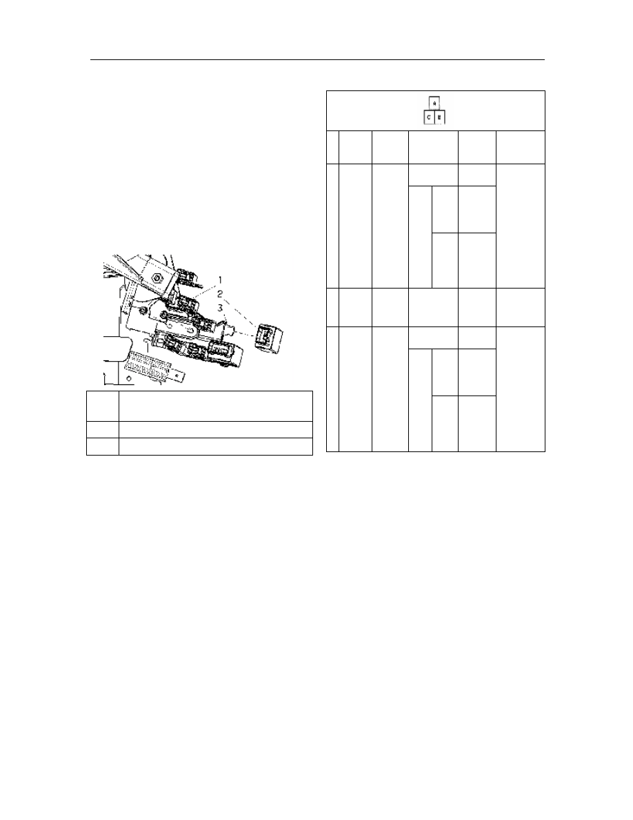
Removal/installation of flasher unit


Note:  The  lock  part  of  this  unit  is  vulnerable.  If 
unnecessary  for replacement, do not remove it  from 
the  bracket.  Prior  to  the  removal,  be  sure  to  check 
first the flasher unit. 

1. 

Disconnect battery negative cable; 

2. 

Remove the bracket; 

3. 

Disconnect the connector of flasher unit; 

4. 

Pry  up  with  a  flathead  screwdriver  the  upper 
part of lock piece and remove the flasher unit; 

5. 

The  installation  procedure  is  in  reverse  order 
with that of removal. 


Fixing  nut  HQ99940-0600 (torque: 7.2~12 
N.m) 

Flashing relay   

Bracket component 


Test of flasher unit


1. 

Remove  the  bracket  and  draw  it  toward 
yourself; 

2.    Measure the terminal  voltage  of  flasher unit as 

shown in Fig. 

3.    Disconnect  the  negative  cable  of  battery  prior 

to check of the continuity of terminal C.   

4. 

If  it  fails  to  meet  the  technique  requirements, 
check  all  parts  listed  in  the  following  table.  If 
the  components  and  harnesses  are  normal,  but 
the  system  still  works  improperly,  replace  the 
flasher unit. 

Table of terminal voltage (only for reference) 

B+ battery positive voltage


Removal/installation of headlamp relay 


Pin  Signal 

Connected 

to 

Testing 

conditions 

Voltage 

(V)/ 

continuity 

Check position 

Flasher 

unit 

output 

Alarm 
switch 

Alarm 

switch 

On 

Change B+ 

and 0 

l  Alarm 

switch 

l  Steering 

signal 
light 

Alarm 

Switch 
Off 

Ignition 
switch 
in 

the 

ON 
position 

B + 

Ignition 
switch 
in 
LOCK 
or  ACC 
state 

Flasher 

unit 

grounding 

GND 

Continue: 
check 

the 

continuity 

of 

grounding 

Yes 

GND 

Power 
supply 

Alarm 
switch 

Alarm 

switch 

On 

B + 

l  Alarm 

fuse 15A 

l  Instrument 

fuse 15A 

l  Alarm 

switch 

Alarm 
switch 
Off 

Ignition 
switch 
in 

the 

On 
position 

B + 

Ignition 
switch 
in 

the 

LOCK 
or  ACC 
state 

1.    Disconnect battery negative cable; 

2.    Remove the cover of main fuse box; 

3.    Remove the horn relay; 

4.    Remove as per the order indicated in the Table; 

5.    The  installation  procedure  is  in  reverse  order 

with that of the removal. 

-------------------------------------------------------------------------------------------------------------------------------------------------------------

Switch and relay


T-72 


Headlamp relay   

Main fuse box   


Check of headlamp relay 


1. 

Remove the headlamp relay; 

2. 

Check  the  continuity  between  all  terminals  of 
headlamp relays with an ohmmeter. If it fails to 
meet  the  technique  requirements,  replace  the 
headlamp relay. 


Relay circuit diagram 


Element side connector 

(Viewed from the terminal side) 


Removal/installation  of  front  fog  lamp 
relay 


1. 

Disconnect the negative cable of battery; 

2. 

Remove the bracket; 

3. 

Remove the plug of front fog lamp relay; 

4. 

Pry out  the lock part at the side  of relay  with a 
flathead screwdriver to remove the relay. 

5. 

The  installation  procedure  is  in  reverse  order 
with that of removal. 


Check of front fog lamps relay 


1. 

Remove the relay of front fog lamp; 

2.    Check  the  continuity  between  all  terminals  of 

front  fog  lamps  relay  with  an  ohmmeter.  If  it 
fails  to  meet  the  technique  requirements, 
replace the relay of front fog lamp. 


Relay circuit diagram 


Element  side  connector  (viewed  from  the  terminal 
side) 


Removal/installation of rear fog lamp relay 


Note:  The  lock  part  of  relay  is  vulnerable.  Do  not 
remove  the  relay  from  the  bracket  except  for 
replacement.  Prior  to  the  removal,  be  sure  to  check 
the relay. 

1. 

Disconnect battery negative cable; 

2. 

Remove the bracket; 

Continuity 

Terminal 

Steps 

Grounding 

Continuity 

Terminal 

Steps 

Grounding 

-------------------------------------------------------------------------------------------------------------------------------------------------------------

Switch and relay


T-73 

3. 

Disconnect  the  connector  of  rear  fog  lamp 
relay; 

4. 

Pry  up  with  a  flathead  screwdriver,  the  upper 
side  of  lock  part.  Remove  the  relay  rear  fog 
lamp relay. 


5. 

The  installation  procedure  is  in  reverse  order 
with that of removal. 


Check of rear fog lamp relay 


1. 

Remove the bracket and draw toward yourself; 

2. 

Check  the  continuity  between  all  terminals  of 
rear fog lamp relay with an ohmmeter. If it fails 
to meet the technique requirements; replace the 
relay of rear fog lamp relay. 


Relay circuit diagram 


Element side connector (viewed from the terminal 

side) 


Part of alarm system 

Removal/installation of horn 

1. 

Remove the negative cable of battery; 

2. 

Remove the front bumper; 

3. 

Disconnect the connector of horn; 

4. 

Remove the bolts 

5. 

Remove the horn; 

6.    The  installation  procedure  is  in  reverse  order 

with that of the removal. 


1 

Screw HQ99786-0616 (torque: 7.2~12N.M) 

2 

Bodywork 

3 

Horn   


Removal/installation of horn relay 

1.    Remove the negative cable of battery; 

2.    Remove the cover of main fuse box; 

3. 

Remove in the order as indicated in the Table; 

4.    The  installation  procedure  is  in  reverse  order 

with that of the removal.   


Horn relay   

Bracket


Rear fog lamp 

relay


Connector of rear fog 

lamp relay 

Continuity 

Connection terminal 

Steps 

Grounding 

Main fuse box cover 

-------------------------------------------------------------------------------------------------------------------------------------------------------------

Switch and relay


T-74 

Check of horn relay   

1. 

Remove the horn relay; 

2. 

Check  and  confirm  the  continuity  between  the 
terminals of horn relay, with an ohmmeter. If it 
fails  to  meet  the  technique  requirements, 
replace horn relay. 


Disassembly and assembly of clock spring 


1   

Screws   

2   

Clock spring   

See  Essentials  to  Installation  of  Clock 
Spring   

3   

Connector   

1. 

Remove the negative cable of battery; 

2. 

Dismantle  the  main  safety  airbag  module. 
Please  refer  to  the  “Disassembly/Assembly  of 
Driver Sided Airbag Module” 

3. 

Pull  out  all plugs  of  steering  wheel  connecting 
the clock spring; 

4. 

Dismantle  the  fixing  nuts  of  steering  wheel. 
The  tightening  torque  for  the  fixing  nuts  of 
steering wheel: 25 N.m.; 

5. 

Align  the  steering  wheel  with  the  center  and 
make  it  stay  at  the  lock  position, and  take  out 
steering wheel;   

6. 

Dismantle  all  screws  on  the  upper/lower  cover 
of  steering  column  and  take  out  the  lower 

cover; 

7. 

Pull  out  all  connectors  connecting  the  lower 
end of clock spring; 

8. 

Dismantle three screws fixing the clock spring.   

9. 

Take  out  the  clock  spring  from  the  steering 
wheel.   


Warning:  Prior  to  the  installation,  be  sure  that 
the clock spring stays in the center. 

10.  Keep the center of clock spring aligned. 

1)    The  pin  can  be  removed  only  after  the  clock 

spring has been installed; 

2)    For  the  clock  spring  without  the  location  pin, 

the  installation  is  allowed  only  with  the  center 
aligned;   

(1)    Turn  clockwise  up to  extreme position (until  it 

cannot rotate any further);   

(2)  Turn  counterclockwise  about  2.75  circles  until 

the arrow on the clock spring aligned. 

11.  Reassemble  the  rest  of  parts  in  the  reverse 

order. 


Essentials to installation of clock spring   

Attention   

If  the  clock  spring  is  not  aligned,  the  clock  spring 
wire  will  break  due  to  excessive  tension  when  the 
steering  wheel  is  turned.  Note  to  make  adjustment 
after the clock spring has been installed. 


Adjustment of clock spring   

Note:  The  adjustment  process  is  also  described  in 
the warning label of clock spring. 

1. 

Turn the steering wheel to face the front wheel 
forward. 

Attention: If the clock spring is too tense, it will be 
damaged. Do not forcibly turn the clock spring. 

2. 

Turn clockwise the clock spring till to the end. 

Continuity 

Terminal 

Steps 

-------------------------------------------------------------------------------------------------------------------------------------------------------------

Switch and relay


T-75 


3.    Turn  counterclockwise  the  clock  spring  for  2 

and 3/4 circles. 


4.    Align the mark on the clock spring with that on 

the outer circle. 


Align with the mark


-------------------------------------------------------------------------------------------------------------------------------------------------------------


Content      ..     4      5      6