Haima 7. Electrical System of Body. Service Manual - part 5
 

  Index      Haima     Haima 7. Electrical System of Body. Service Manual


Search            copyright infringement  


Content      ..     3      4      5      6     ..


Haima 7. Electrical System of Body. Service Manual - part 5


Safety airbag system 

T-55 


5. 

Connect  the  red  clamp  of  special  release  tool 
with  battery  positive  terminal,  and  the  black 
clamp with battery negative terminal. 

6. 

Confirm that the red light on the special release 
tool is lit. 

7. 

Be  sure  that  all  staff  stay  at  least  5m  {20ft} 
away from the vehicle. 

8. 

Press  the  trigger  switch  on  the  special  release 
tool to release the occupant--sided safety airbag 
module. 


Pretensioning safety belt 

1. 

Remove  the  lower  interior  trim  panel  of  the 
column B 

2. 

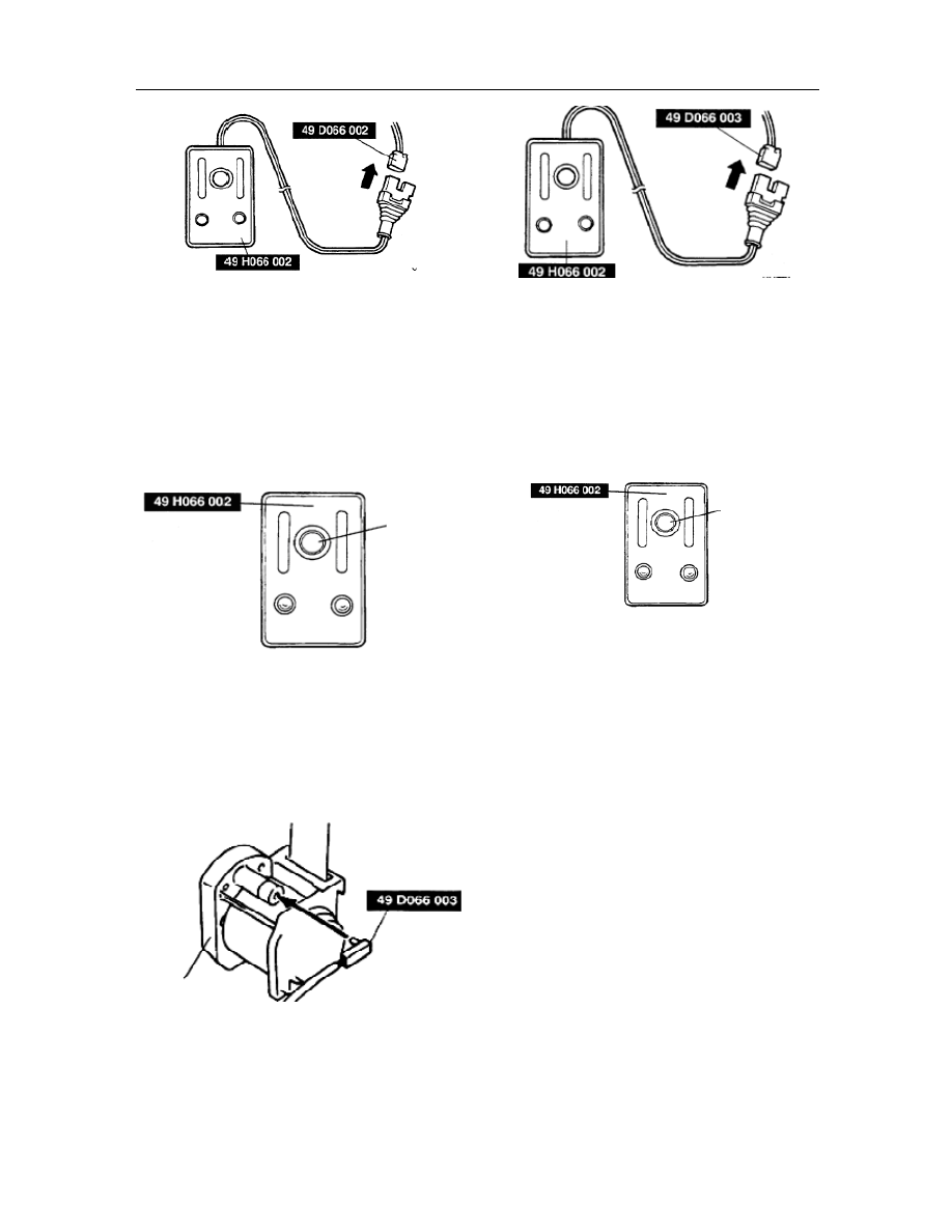
As  shown  in  Fig.,  remove  the  pretensioning 
safety  belt  and  connect  the  switch  harness  of 
special tool with the pretensioning safety belt. 


3. 

Install the pretensioning safety belt. 

4. 

Connect the special release tool with the switch 
harness of special tool. 


5. 

Connect  the  red  clamp  of  special  release  tool 
with  battery  positive  terminal,  and  the  black 
clamp with battery negative terminal. 

6. 

Confirm that the red light on the special release 
tool is lit. 

7. 

Be  sure  that  all  staff  stay  at  least  5m  {20ft} 
away from the vehicle.   

8. 

Press  the  trigger  switch  on  the  special  release 
tool to release the pretensioning safety belt. 


Release procedure outside vehicle   

1. 

Check the special release tool. 

2. 

Turn the ignition switch to the LOCK position. 

3. 

Remove the  negative  cable  of battery  and  wait 
for more than 1min. 

4. 

Release  as  per  the  suitable  procedure  the 
driver-sided 

safety 

airbag 

module, 

occupant–sided  safety  airbag  module  or 
pretensioning safety belt. 


Driver-sided safety airbag module 

1. 

Remove the driver-sided safety airbag module; 

2. 

Install  the  bolts  on  the  driver-sided  safety 
airbag module. 

Trigger 
switch


Pretensioning safety 

belt 

Trigger 
switch


-------------------------------------------------------------------------------------------------------------------------------------------------------------

Safety airbag system 

T-56 


Warning: 

If  the  safety  airbag  module  incorrectly  installed  on 
the tire, the release  of  module  may result in serious 
personnel  injury.  When  the  safety  airbag  module  is 
installed  on  the  wheel,  the  module  shall  face 
upwards. 

Place  the  driver-sided  safety  airbag  module  on  the 
center  of  wheel  module  upward  and  fix  the  safety 
airbag  module  on  the  tire.  Pass  a  cable  through  the 
wheel and bundle up the bolt at least circles. 


4. 

As shown in Fig., connect the switch harness of 
special  tool  with  the  driver-sided  safety  airbag 
module. 


5. 

Place  three  tires  on  the  wheel  with  the  safety 
airbag module, and one tire with rim on 4 tires. 


6. 

Use wires to bundle up all tires. 


7. 

Connect the special release tool with the switch 
harness of special tool. 


8. 

Connect  the  red  clamp  of  special  release  tool 
with  battery  positive  terminal,  and  the  black 
clamp with battery negative terminal. 

9. 

Confirm that the red light on the special release 
tool is lit. 

10.  Be  sure  that  all  staff  stay  at  least  5m  {20ft} 

away from the vehicle. 

11.  Press  the  trigger  switch  on  the  special  release 

tool  to  release  the  driver-sided  safety  airbag 
module. 


Bolt


Module connector of driver-side 

safety airbag 

Module connector of 

driver-side safety airbag 

Wire 

Tire with rim 

Tire with the module of 

driver-side safety airbag 

Tire 

Trigger 
switch


-------------------------------------------------------------------------------------------------------------------------------------------------------------

Safety airbag system 

T-57 


Occupant-sided safety airbag module 

1. 

Remove  the  occupant-sided  safety  airbag 
module. 

2. 

Install  the  bolts  on  the  occupant-sided  safety 
airbag module. 

Warning: 

If  the  safety  airbag  module  incorrectly  installed  on 
the tire, the release  of  module  may result in serious 
personnel  injury.  When  the  safety  airbag  module  is 
installed  on  the  wheel,  the  module  shall  face  the 
center of tire. 

3. 

Bund  up  the  occupant-sided  safety  airbag 
module  on  the  tire  with  the  module  facing  the 
center  of  tire.  Pass  a  cable  through  the  wheel 
and bundle up the bolt at least 4 circles. 


4. 

As shown in Fig., connect the switch harness of 
special  tool  with  the  occupant-sided  safety 
airbag module. 


5. 

Stack  the  tires  with  the  occupant-sided  safety 
airbag module on 2 tires, and one tire on 3 tires, 
and another tire with rim on 4 tires. 


6. 

Use wires to bundle up all tires. 


7. 

Connect  the  special  release  tool  with  switch 
harness of special tool. 


8. 

Connect  the  red  clamp  of  special  release  tool 
with  battery  positive  terminal,  and  the  black 
clamp with battery negative terminal. 

9. 

Confirm that the red light on the special release 
tool is lit. 

10.  Be  sure  that  all  staff  stay  at  least  5m  {20ft} 

away from the vehicle.   

11.  Press  the  trigger  switch  on  the  special  release 

tool to release the  occupant-sided safety  airbag 
module 

Tire 

Wire 

Module of occupant 

-side safety airbag 

Tire 

Tire with rim 

Module of 

occupant-side 

safety airbag 

-------------------------------------------------------------------------------------------------------------------------------------------------------------

Safety airbag system 

T-58 


Pretensioning safety belt 

1. 

Remove the pretensioning safety belt. 

Warning: 

If  the  safety  airbag  module  incorrectly  installed  on 
the tire, the release  of pretensioning part  may  result 
in serious personnel injury.  When  the pretensioning 
safety belt is installed on the tire, it shall be posed in 
the tire. 

2. 

As shown in Fig., connect the switch harness of 
special tool with the pretensioning safety belt. 


3. 

Bundle  up the pretensioning safety belt and fix 
it  in  the  tire,  pass  wires  through  the  tire  and 
bundle  up  the pretensioning safety belt  at  least 
4 circles. 


4. 

Stack the tire with the pretensioning safety belt 
on  2  tires, one  on  3  tires  and  another  with  the 
rim on 4 tires. 


5. 

Bundle up all tires with wires. 


6. 

Connect the special release tool with the switch 
harness of special tool. 


7. 

Connect  the  red  clamp  of  special  release  tool 
with  battery  positive  terminal,  and  the  black 
clamp with battery negative terminal. 

8. 

Confirm that the red light on the special release 
tool is lit. 

9. 

Be  sure  that  all  staff  stay  at  least  5m  {20ft} 
away from the vehicle. 

10.  Press  the  trigger  switch  on  the  special  release 

tool  to  release  the  pretensioning  safety  airbag 
module. 

Trigger 
switch


Pretensioning 

safety belt 

Tire 

Wire


Pretensioning 

safety belt 

Tire with rim 

Tire 

Tire with 

pretensioning safety 

belt 

-------------------------------------------------------------------------------------------------------------------------------------------------------------

Safety airbag system 

T-59 


Released 

safety  airbag 

module 

and 

pretensioning safety belt 

After  the  safety  airbag  module  and  pretensioning 
safety  belt  just  released,  the  high  temperature  may 
result  in  scald.  Do  not  touch  relevant  parts  within 
15mins  after  the  safety  airbag  module  and 
pretensioning safety belt released. 

It  is  dangerous  to  water  the  released  safety  airbag 
module  and  pretensioning  safety  belt.  The 
combination  of water  with residual  air will produce 
gas  hard  to  breathe.  Hence,  do  not  water  the 
released  safety  airbag  module  and  pretensioning 
safety belt. 

The released safety airbag module and pretensioning 
safety  belt  may  contain  the  sodium  hydroxide 
precipitate,  a  corrosive  byproduct  produced  from 
gas combustion. If this substance gets into eyes or in 
contact  with  the  hands, it  can  cause  discomfort  and 
itching. When handling with a released safety airbag 
module and pretensioning safety belt, you should   

2. 

Wear the gloves and safety goggles. 


Place 

the 

safety 

airbag 

module 

and 

pretensioning safety belt into a plastic bag. Seal 
up the plastic bag and then have it disposed 

3.    Take off the gloves and wash hands. 


Check of special release tool   

Prior  to  handling  the  safety  airbag  module  and 
pretensioning  safety  belt  not  yet  released  under 
working  state,  use  a  special  release  tool  to  release 
them. Before  use  of a special release  tool, check its 
work condition. 


Checking procedure 

Check  and  confirm  that  the  special  release  tool 
operates  properly  as  per  the  following  steps.  If  it 
fails to meet the technique requirements, do not  use 
the  special  release  tool,  because,  it  may  result  in 
sudden  releases  of  the  safety  airbag  module  and 
pretensioning  safety  belt,  if  it  is  connected  with  the 
safety airbag module or pretensioning safety belt. 

Steps 

Check procedures 

State of 

indicator light 

Green 

Red 

Connect  the  red  clamp 
with  battery  positive 
terminal  and  the  black 
clamp  with  the  battery 
negative terminal 

Lit 

Unlit 

Connect  the  connector 
A  of  special  release 
tool  with  the  connector 
B. 

Unlit 

Lit 

Press the trigger switch 

Lit 

unlit 


Trigger 
switch


Clamp 

Connector A 

Connector B 

Green light 

Trigger switch 

Red light 

Red clamp 

Black clamp 

-------------------------------------------------------------------------------------------------------------------------------------------------------------

Safety airbag system 

T-60 


Connector A 

Trigger switch 

Connector B 

-------------------------------------------------------------------------------------------------------------------------------------------------------------

RKE (Remote Control System)


T-61 

RKE (Remote Control System) 

Removal/installation of remote controller 

1. 

Remove the negative cable of battery; 

2. 

Disconnect the connector of remote controller; 

3. 

Dismantle  with  a  wrench  the remote  controller 
and mounting bracket from the bodywork.


4.    The  installation  procedure  is  in  reverse  order 

with that of the removal. 


Check of remote controller   

1. 

In case, where the door or trunk lock cannot be 
unlocked, or  door lock  light cannot be  turn  off 
by  remote  control  in  normal  use, it  means  that 
there  is  a  fault  in  the  remote  center  control 
transmitter or the host. 

2. 

Confirm  whether  the  battery  of  remote  central 
control  transmitter  needs  to  replace.  The 
replacement  procedure  is  referred  to  in  the 
product instruction manual. 

3. 

If  the  problem  persists  after  the  remote  central 
control  transmitter  replaced,  confirm  whether 
the  harness  is  in  sound  connection,  the 
actuating  device  of  door  or  trunk  lock  is 
normally  operating  and  the  door  lock  relay 
intact. 

4. 

If  everything is in  order after the  above  check, 
it  means  that  there  is  a  fault  in  the  remote 
controller,  and  the  remote  controller  shall  be 
replaced. 


Reversing radar system   

Removal/installation  of  reversing  radar 
host 

1. 

Remove the negative cable of battery; 

2. 

Disconnect  the  connector  of  reversing  radar 
host; 

3. 

Dismount  with  a  wrench  the  reversing  radar 
host and mounting bracket from the bodywork.


4. 

The  installation  procedure  is  in  reverse  order 
with that of removal.   


Check of reversing radar host   

1. 

When there are wrong alarms in  normal  use  of 
reversing radar system, it means there is a fault 
in the reversing radar sensor or host 

2. 

Confirm  whether  the  harness  connecting  the 
reversing radar system is intact. 

3. 

Check  whether  the  reversing  radar  sensor  has 
any  problems.  The  check  method  is  shown  as 
below:   

1)    Shut  down,  and  check  whether  there  are  any 

foreign  matters  on  the  surface  of  reversing 
radar sensor. 

2)    Set the ignition switch on the ON position. 

3)    Place  the  shift  mechanism  on  the  reverse 

position. 

4) 

Record  the  following  beep  mode  of  buzzer;  If 
the reversing  radar sensor just  “beeps”  once, it 
means  there  is  no  faults  in  the  reversing  radar 
sensor,  if  it  sounds  twice  like  “BI”“BI”!,  it 
means there  is problem in  one  of the reversing 

RKE and reversing 

radar host bracket 

Harness 

connector 

Mounting screw 

RKE host 

Reversing 
radar host 

RKE and reversing 

radar host bracket 

Harness joint 

Mounting screw 

RKE host 

Reversing 
radar host 

-------------------------------------------------------------------------------------------------------------------------------------------------------------

Safety airbag system 

T-62 

radar sensors, if three beeps like “BI”“BI”“BI”, 
it  means  there  may  be  faults  in  two  or  more 
reversing radar. 

5)    If there is  a  fault in the reversing radar sensor, 

please replace the fault reversing radar sensor. 

4. 

If  everything  is in  order after check  mentioned 
as above, it means there are faults in the remote 
controller  and  need  to  replace  the  remote 
controller.


Removal/installation  of  reversing  radar 
sensor 


1. 

Remove battery negative cable; 

2. 

Disconnect  the  connector  of  reversing  radar 
sensor. 

3. 

Remove the snap spring. 

4. 

Pull  out  the  reversing  radar  sensor  from  the 
mounting hole of rear bumper. 

5. 

The  installation  procedure  is  in  reverse  order 
with that of removal. 


Rear bumper 

Reversing radar sensor 

Snap spring 

-------------------------------------------------------------------------------------------------------------------------------------------------------------

Anti-theft system 

T-63 

Anti-theft system 

Removal/installation  of  anti-theft  host 
controller 

Attention: 

As  the  lock-plate  of  host  is  vulnerable  part,  do  not 
remove  the  module  from  the  bracket  except  for  the 
module replacement. A check shall be made prior to 
the removal of the controller of anti-theft host. 

1. 

Remove battery negative cable; 

2. 

Disconnect  the  connector  of  anti-theft  host 
controller; 

3. 

Pry  up  by  use  of  a  flat  head  screwdriver  the 
lock-plate at the side of module and remove the 
anti-theft host controller.


4. 

The  installation  procedure  is  in  reverse  order 
with that of the removal.


Check of anti-theft host controller   

1. 

When  the anti-theft  alarm  light  of  combination 
instrument  cannot  be  normally  activated  or 
keeps  intermittently  flickered  after  started,  it 
indicates  that  there  are  faults  in  the  engine 
system. 

2. 

Confirm  whether  the  harness  of  anti-theft 
system is in good connection 

3. 

Confirm  whether  ECU  is  sound  (specifically 
referred  to  the  Power  System  Maintenance 
Manual- ECU). 

4. 

Test with the diagnostic apparatus the anti-theft 
system,  and  record  the  fault  codes.  Make 
treatment as per fault code.   

5. 

Remove  the  controller  of  anti-theft  host  and 
maintain the connection of connector; 

6. 

Measure  the  voltage  of  the  controller  terminal 
of anti-theft host, as shown in Fig. below; 

7. 

If  it  fails  to  meet  the  technique  requirements, 
check the parts listed in the item column. If the 

parts and harnesses are in order, but the system 
is  still  unable  to  work  properly,  replace  the 
controller  of  anti-theft  host  and  redo  the 
matching.  Please  pay  special  attention  to  the 
matching precautions.


List of terminal voltage (only for reference) 


Connector at harness side (viewed from the terminal 
side)


Removal/installation of anti-theft coil 

Pin 

Definition of pin 

Rated 

voltage 

Operating 

current 

Requirement 

of harness 

1A 

ROOM  fuse  power 
supply 

12V 

<200mA 


1B 

Grounding 

0V 

<200mA 


1C 

Access 

to 

the 

combination 
instrument 1Q 

... 

<200mA 


1D 

Power supply IG1 

12V 

<200mA 


1E 

Access to R-LINE 

12V 

<200mA 


1F 

No connection 

... 

… 


1G 

Access to K-LINE 

12V 

<200mA 


1H 

Access to W-LINE 

12V 

<200mA 


2A 

Terminal  A  of  coil 
connector 

... 

… 


2B 

Terminal  B  of  coil 
connector 

... 

… 


2C 

GND 

... 

… 


1. 

Remove the negative cable of battery. 

2. 

Remove  the  anti-theft  coil  from  the  ignition 
lock. 

Anti-theft controller 

host 

Mounting bracket 

Harness plug 

Connector 2 

-------------------------------------------------------------------------------------------------------------------------------------------------------------

Safety airbag system 

T-64 


3. 

The  installation  procedure  is  in  reverse  order 
with that of removal.   


Precautions to installation: 


Install  firstly  the  barb  1  on  the  ignition  lock,  and 
then the barb 2 on the ignition lock.


Check of anti-theft coil   

1.    Sometimes  the  engine  cannot  be  started  by 

normal  starting  method.  The  problem  persists 
after  the  faults  of  controller  and  ECU 
troubleshot,  which  means  there  are  still 
problems in the anti-theft coil. 

2. 

Check  whether  the  harness  connecting  the 
anti-theft  coil  and  controller  is  in  sound 
condition. 

3. 

Test  with  the  diagnostic  apparatus,  the 
anti-theft  system.  If  the  communication  is 
disabled  due  to  the  faults  of  transmitter  and 
anti-theft  controller, it  means there is a  fault in 
the anti-theft coil. 

4. 

Remove  the  anti-theft  coil,  and  use  a 
multimeter  to  check  the  connectivity  of  two 
PINs as follows.


Connector at harness side 


Note:  When  checking,  connect  the  PIN  A  with  the 
PIN C. 

5. 

If  failed  to  get  through,  it  means  that  the 
anti-theft  coil  is  damaged.  Replace  the 
anti-theft coil.


Barb 3


Barb 2


Barb 1


-------------------------------------------------------------------------------------------------------------------------------------------------------------

Switch and relay 

T-65 

Switch and relay   

Removal/installation of combination switch 

1.    Disconnect battery negative cable; 

2.    Remove  the  driver-sided  safety  airbag  module 

(See  T—Removal/Installation  of  Driver-Sided 
Safety Airbag Module); 

3.    Remove 

the 

steering 

wheel 

(See 

N—Removal/Installation  of  Steering  Wheel 
and Steering Column); 

4    Remove the steering column cover; 

5    Remove 

the 

clock 

spring 

(See 

T—Removal/Installation of Clock Spring); 

6    Remove as per the order indicated in the Table; 

7    The  installation  procedure  is  in  reverse  order 

with that of removal. 


Connector   

Screw HQ99834-0510 (3.9~5.9 N.m) 

Combination switch 


Disassembly/assembly 

of 

combination 

switch


1. 

Loosen R/L screws; 

2. 

Remove  separately  the  switches  of  wipers, 
washers and lamps; 

3. 

The  assembly  procedure  is  in  reverse  order  of 
that of disassembly; 


1   

Screw   

2   

Wiper and washer switches 

3   

Auto lamp switch 

4   

Combination switch   


Removal/installation of auto lamp switch


1. 

Disconnect battery negative cable; 

2.    Remove the steering column cover; 

3.    Remove as per the order indicated in the Table; 

4.    The  installation  procedure  is  in  reverse  order 

with that of the removal. 


Connector   

Screw   

Auto lamp switch 


Check of auto lamp switch


1.    Remove auto lamp switch; 

2.    Check  with  an  ohmmeter  the  continuity 

between the terminals of auto lamp switch. If it 
fails  to  meet  the  technique  requirements, 
replace the auto lamp switch. 


Headlamp switch 


Switch position 

Terminal 

Continuity 

Bright 

Dark 

Flashing by 

Off 

Off 

Off 

Off 

On 

On 

On 

Headlamp 

Low 

High 

-------------------------------------------------------------------------------------------------------------------------------------------------------------

Switch and relay


T-66 


Switch circuit diagram 


Element side connector 


Steering switch 


Element side connector 


Removal/installation of middle switch


1. 

Disconnect battery negative cable; 

2. 

Remove the auxiliary fascia console; 

3. 

Pry,  with  a  screwdriver,  three  clamps  on  the 
middle switch and auxiliary fascia console; 

4. 

Take  out  the  switch  from  the  mounting  hole 
below. 

5. 

Disconnect  the  switch  connector  of  hazard 
warning  light.  Remove  the  hazard  warning 
light switch. 

6.    The  method  of  installation  is  in  reverse  order 

with that of removal. 


Middle  switch  (incl.  hazard  warning  light 
switch and door lock switch) 

Auxiliary fascia console 


Maintenance of middle switch


1. 

Remove the switch; 

2. 

Check  by  use  of  a  multimeter,  the  continuity 
between  the  switch  terminals  according  to  the 
diagram.  If  it  fails  to  meet  the  technique 
requirements, replace the switch. 


Removal/installation of front/rear fog lamp 
switch


1.    Disconnect battery negative cable; 

2.    Remove the side panel of dashboard; 

Flashing 

by 

Headlamp 

High 

Low 

Off 

Continuity 

Switch position 

Terminal 

Off 

Backlight 


Backlight 


Backlight 

Central control 

lock (locked) 

Hazard 

warning light 

Central control 

door lock 

(unlocked) 

Middle switch diagram 

Middle switch terminal definition


-------------------------------------------------------------------------------------------------------------------------------------------------------------

Switch and relay


T-67 

3.    Compress  by  hands  the  upper/lower  snaps  on 

the  switch  behind  the  dashboard  until  the 
switch  is  able  to  pass  through  the  mounting 
hole; 

4.    Take out the switch; 

5.    The  installation  procedure  is  in  reverse  order 

with that of the removal. 


Front/rear fog lamp switch 

Dashboard   


Check of front/rear fog lamp switch


1. 

Remove the switches of front/rear fog lamp. 

2. 

Test  by  use  of  a  multimeter,  the  continuity 
between  the  switch  terminals  according  to  the 
diagram.  If  it  fails  to  meet  the  technique 
requirements, replace the switch. 


Removal and installation of rheostat


1.    Disconnect battery negative cable; 

2.    Remove the side panel of dashboard; 

3.    Compress  by  hands  the  upper/lower  snaps  on 

the  switch  behind  the  dashboard  until  the 
switch  is  able  to  pass  through  the  mounting 
hole; 

4.    Take out the switch; 

5.    The  installation  procedure  is  in  reverse  order 

with that of the removal. 


Rheostat   

Dashboard   


Check of rheostat


1. 

Remove the rheostat; 

2. 

Test  by  use  of  a  multimeter,  the  continuity 
between the rheostat terminals according to the 
diagram.  If  it  fails  to  meet  the  technique 
requirements, Replace rheostat. 

Snaps of upper/lower ends 

Front fog 

lamp switch 

Rear fog lamp 

switch 

Backlight 

Front/rear fog lamp switches diagram 

Definition of the front/rear fog 

lamp switch terminals 

Snaps of upper/lower ends 

-------------------------------------------------------------------------------------------------------------------------------------------------------------

Switch and relay


T-68 


Installation/removal  of  level  adjustment 
switch (optional)


1.    Disconnect the negative cable of battery; 

2.    Remove the side panel of dashboard; 

3.    Compress  by  hands  the  upper/lower  snaps  on 

the  switch  behind  the  dashboard  until  the 
switch  is  able  to  pass  through  the  mounting 
hole; 

4.    Take out the switch; 

5.    The  installation  procedure  is  in  reverse  order 

with that of the removal.   


Dashboard   

Level adjustment switch 


Check of level adjustment switch


1. 

Remove the switch of level adjustment; 

2. 

Test  by  use  of  a  multimeter,  the  continuity 
between the rheostat terminals according to the 
diagram.  If  it  fails  to  meet  the  technique 
requirements, Replace rheostat. 


Installation/removal  of  folding  switch  of 
rear-view mirrors (optional)


1.    Disconnect battery negative cable; 

2.    Remove the side panel of dashboard; 

3.    Compress  by  hands  the  upper/lower  snaps  on 

the  switch  behind  the  dashboard  until  the 
switch  is  able  to  pass  through  the  mounting 
hole; 

4.    Take out the switch; 

5.    The  installation  procedure  is  in  reverse  order 

with that of the removal. 


Folding switch of rear-view mirrors 

Dashboard   


Circuit diagram 

Snaps of upper/lower ends 

Diagram


Snaps


-------------------------------------------------------------------------------------------------------------------------------------------------------------

Switch and relay


T-69 

Check  of  folding  switch  of  rear-view 
mirrors


1. 

Remove  the  folding  switch  of  rear-view 
mirrors; 

2. 

Check,  with  a  multimeter  the  continuity  of 
switch  terminal  according  to  the  diagram.  If  it 
fails  to  meet  the  technique  requirements, 
replace the switch. 


Removal/installation  of  power  window 
switch 

Removal/maintenance  of  main  power 
window switch


1.    Remove battery negative cable; 

2.    Pry  out  the  switch  panel  by  use  of  a  straight 

screwdriver; 

3.    Disconnect the main switch connector of power 

window; 

4.    Remove  the  mounting  screw  by  use  of  a 

screwdriver; 

5.    The  installation  procedure  is  in  reverse  order 

with that of the removal.   


Left front door assembly 

Switch panel of power window   

Main power window   

Self-tapping  screw  HQ99874-0412  (torque: 
not more than 2.9


N.m) 


Check of main power window switch


1. 

Sometimes,  there  are  cases  such  as  the  power 
windows  cannot  move  up/down  or  the  main 
switch  of  power  window  having  the  anti-trap 
function cannot efficiently perform its function 
when  the  main  switch  of  power  window  is 
normally operated. 

2. 

Confirm that the harness led to the main switch 
of  power  window  is  in  sound  connection,  the 
anti-trap  stop  switch  and  window  regulator 
operate  in  normal  state,  the  auxiliary  power 
window switch in  normal performance  and the 
lock switch not pressed down. 

3. 

If  the  window  regulator  is  still  unable  to  work 
properly,  it  means  the  main  switch  of  power 
window  is  damaged,  please  replace  the  main 
switch of power window; 

4. 

If the anti-trap function ineffective or unable to 
properly  close  the  windows,  please  check 
whether  there  is  pulse  signal  issued  from  the 
window regulator  of  left  front  door. The  check 
method of pulse signal is shown as below: 

1)    Use an oscillograph; 

2)    Connect  the  signal  terminal  of  oscillograph 

with the PIN D as shown in Fig. below:   


Connector at harness side 


Diagram of folding switch of 

rear-view mirrors 

Terminal definition of folding switch 

of rear-view mirrors 

Folding 

state 

-------------------------------------------------------------------------------------------------------------------------------------------------------------

Switch and relay


T-70 

3)    Confirm 

other 

harnesses 

are 

properly 

connected  and  the  ignition  key  in  the  ON 
position; 

4)    Observe whether there are pulses under AUTO 

gear.  If  yes,  it  means  that  the  main  switch  of 
power  window  is  damaged.  Please  replace  the 
main switch of power window; 

5)    If  no  pulses  available, please  confirm  whether 

the window regulator has the anti-trap function. 
If it does, it means that the window regulator is 
damaged,  please  carry  out  the  maintenance  in 
reference to  the  window regulator maintenance 
of accessory system. 

5. 

If  unable  to  properly  close  the  windows  (It 
behaves  in  such  manner  that  the  window 
bounces  back  automatically  after  raised  to  the 
top, which hinders the window to close), please 
check  whether  the  PIN  B  shown  in  the  above 
Fig.  is  disconnected  when  raised  to  the  top.  If 
yes,  it  means  that  the  main  switch  of  power 
window was damaged. Please replace the main 
switch of power window. 


Installation/removal  of  auxiliary  power 
window


1. 

Remove the negative cable of battery; 

2. 

Pry  out  the  switch  panel  with  a  straight 
screwdriver. 

3. 

Disconnect  the  connector  of  power  window 
switch; 

4. 

Remove  the  mounting  screws  by  use  of  a 
screwdriver; 

5. 

The  installation  procedure  is  in  reverse  order 
with that of removal. 


Switch panel of aux. power window switch 

Aux. power window   

Self-tapping  screw  HQ99874-0412  (torque: 
not more than 2.9


N.m) 

Door  assembly  (incl.  right  front  and  rear 
doors) 

Installation/removal of front door switch


1. 

Remove the negative cable of battery; 

2. 

Unscrew the fastening screws; 

3. 

Undo the inner trim panel and pull out the plug.   

4. 

Take out the switch; 

5. 

The  installation  procedure  is  in  reverse  order 
with that of removal. 


Self-tapping  bolt  HQ9YA56-0601  (torque: 
6.9~9.8 N.m) 

Door switch 

Note:  the  methods  of  installation/removal  of  front 
doors are just same as those of back doors. 


Test of door switch


1. 

When  the  backlight  brightness  of  dashboard 
cannot  be  properly  adjusted,  please  check 
according to the following steps. 

2. 

Check  whether  the  harness  connecting  the 
rheostat  is  in  sound  connection,  whether  the 
TNS  relay  in  good  performance,  the  small 
switch turned on and properly operated. 

3. 

If  the  problem  persists,  please  remove  the 
rheostat  and  check  whether  the  rheostat  works 
normally.  If  unable  to  work  in  a  sound  way, it 
means  that  the  rheostat  is  damaged,  please 
replace the door switch. 


Front part 

Rear part 

Bodywork 

grounding 

Bodywork 

grounding 

-------------------------------------------------------------------------------------------------------------------------------------------------------------


Content      ..     3      4      5      6     ..