Haima 7. Electrical System of Body. Service Manual - part 4
 

  Index      Haima     Haima 7. Electrical System of Body. Service Manual


Search            copyright infringement  


Content      ..     2      3      4      5     ..


Haima 7. Electrical System of Body. Service Manual - part 4


Audio system 

T-39 

Assembly method:   

1. 

Insert all  connectors behind  the  audio  host  and 
the A/C controller;   

2. 

Before the audio and A/C controller assemblies 
are fit into the dashboard, it is recommended to 
check  first  whether  all  parts  are  operating 
normally  (audio,  Radio,  A/C  compressor 
operation, air volume and mode);   

3. 

Install the audio host and tighten the screws;   

4. 

Insert  the  adapter  cable  plug  behind  the  audio 
panel,  and  place  the  panel,  aiming  the  panel 
snap at the slot on the dashboard, tap clockwise 
the snap on the panel from the left upper angel;   

5. 

Install  the  A/C  controller  and  tighten  the 
screws;   

6. 

Install  the  panel  of  A/C  controller,  and  tap 
clockwise  the  snap  on  the  panel  from  the  left 
upper angel. 


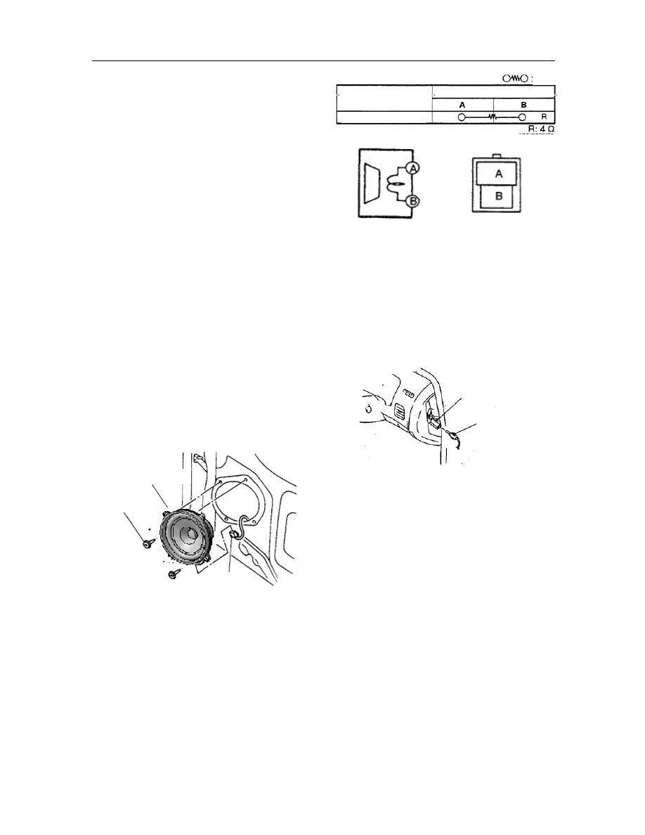
Removal/installation of 4D loudspeaker 

1.    Remove the negative cable of battery; 

2.    Remove 4D inner trim panel; 

3.    Remove the screws; 

4.    Disconnect  the  connectors  of  4D  loudspeaker 

and remove them.


5. 

The  installation  procedure  is  in  reverse  order 
with that of the removal. 


Check of 4D loudspeaker   

1.  Remove 4D loudspeaker; 

2.  Check,  with  an  ohmmeter,  the  resistance 

between  the  terminals  of  loudspeaker.  Replace 
the front door loudspeaker if it fails to meet the 
technique requirements. 


Removal/installation of antenna 

1.    Disconnect  the  negative  cable  connection  of 

battery; 

2.    Remove  the  front  side  trim  panel  at  the  driver 

side; 

3. 

Disconnect the antenna socket on roof;


Removal/installation  of  the  signal  line  of 
front antenna 

1.    Remove the negative cable of battery; 

2.    Remove the audio unit; 

3.    Remove  the  front  side  trim  panel  at  the 

occupant side;


4.    Disconnect  the  connection between  antenna  on 

roof and the signal line of front antenna; 

5.    Remove  as  per  the  following  order.  The 

installation  procedure  is  in  reverse  order  with 
that of removal. 


4D loudspeaker


Screws 

Joint 

Element side connector 

(viewed from the terminal 

side) 

Testing conditions 

Resistance 

Terminal 

Under any conditions 

Antenna feeder 

Roof antenna plug 

-------------------------------------------------------------------------------------------------------------------------------------------------------------

HI-FI System 

T-40 


Clamp   

Signal line of front antenna   


Check of the signal line of front antenna   

1. 

Remove the audio unit; 

2. 

Remove  the  side  panel  of  instrument  panel  at 
driver side; 

3. 

Disconnect  the  connection  between  the  signal 
lines of front/rear antennae; 

4. 

Confirm by use of an ohmmeter that there is no 
continuity  between  the  signal  line  terminals  A 
and B of front antenna; 


5. 

Confirm by  use  of  an  ohmmeter the  continuity 
between  the  signal  line  terminals  of  front 
antenna;  replace  the  dashboard  harness  if  it 
fails to meet the technique requirements 


Removal/installation  of  signal  line  of  rear 
antenna   

1.    Remove the negative cable of battery; 

2.    Remove the audio unit; 

3.    Remove  the  inner  trim  panel  on  the 

occupant-sided column A; 

4.    Remove the roof lining; 

5.    Disconnect  the  connection  between  the  signal 

lines of front/rear antennae; 

6.    Remove in the order indicated in the Table; 

7.    The  installation  procedure  is  in  reverse  order 

with that of the removal.


Screws   

2   

Clamp   

Signal line of rear antenna   


Steps 

Terminal 

: Continuity

-------------------------------------------------------------------------------------------------------------------------------------------------------------

Audio system 

T-41 

Check of rear antenna signal line   

1.    Remove rear antenna signal line; 

2.    Confirm by use of an ohmmeter that there is no 

continuity  between  the  signal  line  terminals  A 
and B of rear antenna 

3.    Confirm by use of an ohmmeter the continuity 

between  the  signal  line  terminals  of  front 
antenna;  replace  the  antenna  signal  line  if  it 
fails to meet the technique requirements 


Steps 

Terminal 

Continuity 

-------------------------------------------------------------------------------------------------------------------------------------------------------------

Safety airbag system 

T-42 

Safety airbag system   

Electrical schematic of safety airbag   


Note:  “”means  the  short-circuit  ring.  When  the  connector  is  not  connected,  the 
short-circuit presents between two wires connected by short-circuit ring.


-------------------------------------------------------------------------------------------------------------------------------------------------------------

Audio system 

T-43 

P

arts relevant to the safety airbag   


The  fault  indicator,  located  in  the  combination  instrument  and  in  red  color,  is 
designated to indicate the state of SRS airbag system. 


PFAB passenger side front row airbag module, located below the dashboard  and in 
front  of  the  front  passenger,  is  designated  to  pop  up  the  airbag  for  the  front 
passenger protection in case of collision. 


DFAB  driver  side  front  airbag  module,  located  in  middle  of  the  steering  wheel,  is 
designated to pop up the airbag for the front driver protection in case of collision. 


CLOCK  SPRING,  located  below  the  steering  wheel,  is  designated  to  connect  the 
buttons of DFAB, horn and steering wheel etc., with the main harness. 


ECU controller of safety airbag, located on the central aisle below the dashboard, is 
designated to control airbag system ignition and test the state of overall system. 


Fault check of safety airbag 

After  the  ignition  switch  set  from  OFF  to  ON  (this 
operation  step  hereafter  referred  to  turn  on  the 
power  supply  switch),  the  fault  indicator  of  safety 
airbag  will  go  off  and  not  lighten  up  anymore  after 
lit  for  6s.  This  means  that  the  airbag  system  is  in 
normal state and no maintenance of airbag system is 
required under such condition. 

If  the  status  indicator  of  safety  airbag  is  not  lit,  or 
keeps lit  constantly  and  flashed etc, after the power 
supply is turned on, it means there is a failure in the 
airbag system and the maintenance of airbag system 
is necessary. 


Fault judgement of safety airbag   

Read  out  fault  log  of  airbag  system  by  use  of  a 
diagnostic  apparatus.  For  use  of  the  diagnostic 
apparatus,  please  refer  to  the  Use  Instructions  of 
diagnostic apparatus. 


-------------------------------------------------------------------------------------------------------------------------------------------------------------

Safety airbag system 

T-44 


Faults table of safety airbag system   

B1301 

ECU internal fault,   

B1302 

Power supply voltage too high 

B1303 

Power supply voltage too low 

B1304 

Driver-sided airbag resistance high 

B1305 

Driver-sided airbag resistance low 

B1306 

Driver-sided airbag short-circuited with the grounding 

B1307 

Driver-sided airbag short-circuited with the power supply 

B1308 

High airbag resistance of front seat occupant   

B1309 

Low airbag resistance of front seat occupant   

B1310 

Airbag of front seat occupant short-circuited with the grounding 

B1311 

Airbag of front seat occupant short-circuited with the power supply 

B1312 

High pre-tensioner resistance of driver safety belt   

B1313 

Low pre-tensioner resistance of driver safety belt 

B1314 

Pre-tensioner of driver safety belt short-circuited with the grounding 

B1315 

Pre-tensioner of driver safety belt short-circuited with the power supply 

B1316 

High pre-tensioner resistance of the safety belt of front seat occupant   

B1317 

Low pre-tensioner resistance of the safety belt of front seat occupant   

B1318 

Safety belt pre-tensioner of front seat occupant short-circuited with the grounding 

B1319 

Safety belt pre-tensioner of front seat occupant short-circuited with the power supply 

B1320 

Fault indicator short-circuited with the grounding or not connected. 

B1321 

Fault indicator short-circuited with the power supply 

B1322 

Wrong setting 

B1324 

Occupant airbag switch short-circuited with the grounding 

B1325 

Abnormal resistance of occupant airbag switch. 

B1326 

Occupant airbag switch short-circuited with the power supply or open-circuited 

B1327 

Off-indicator  of  occupant  airbag  short-circuited  with  the  grounding  or  the  circuit 
disconnected   

B1328 

Off-indicator of occupant airbag short-circuited with the power supply 

Others 

Other faults 


Maintenance procedure of safety airbag   

1. 

Fault  indicator  not  lit  after  the  power  supply 
turned on 

1)    Whether  the  fault  log  can  be  read  out  through 

the diagnostic apparatus. 


Yes: To the step (3)     


No: To the step (2) 

2) 

Check  whether  the  restraint  indicator  of 
occupant  airbag  displays  ON  in  condition  that 
the  occupant  airbag  indicator  switch  is  in  the 
On  position,  and  lit  after  the  power  supply 
turned on and gone off in 4s. 


Yes:  Check  the  diagnostic  interface  and 
relevant harness. 


No: Replace the safety airbag controller. 

-------------------------------------------------------------------------------------------------------------------------------------------------------------

Safety airbag system 

T-45 

3)    Handle as per the following fault log. 

2. 

Fault indicator constant on 

1)    Whether  the  fault  log  can  be  read  out  through 

the diagnostic apparatus. 


Yes: To the step (2) 


No: To the step (3) 

2)    When the fault reason read out, take disposal as 

per the method in the following fault log: 

3)    Check  whether  the  safety  airbag  fuse,  relevant 

power supply harness are normal or not. 

4)    Check  whether  the  controller  connector  of 

safety airbag is normal. 


3. 

Fault indicator flashing 


Read  out  through  the  airbag  fault  diagnostic 
apparatus,  the  fault  log  and  dispose  as  per  the 
method in the following fault log. 


4. 

There is an ECU internal fault in the fault log.   


Replace the controller of safety airbag 


5. 

Power supply  too low  or  high in  fault  log Test 
the power supply system of vehicle 


6. 

There  are  driver  airbag  malfunctions  in  the 
fault  log  (resistance  low/high,  short-circuited 
with the grounding, or with the power supply). 

1)    Low resistance 

(1)    Pull  out  the  driver  airbag  module  to  test 

whether the fault disappeared. 


Yes: Replace the driver airbag module     


No: To the step (2) 

(2)    Pull  out,  below  the  clock  spring,  the  harness 

connector  wrapped  in  middle  with  the  yellow, 
to test whether the fault disappeared. 


Yes: Replace the clock spring       


No: To the step (3)   

(3)    Replace  the  controller  of  safety  airbag, to  test 

whether the fault disappeared. 

(4)    Check  whether  there  are  any  short-circuits 

occurred  between  the  harnesses;  pay  attention 
to  the  short-circuit  ring  in  the  connector  in 
connection with the controller. 

2)    High resistance 

(1)    Check  whether  the  connectors  between  the 

driver airbag module and clock spring, between 
the  clock  spring  and  harness  and  between  the 
harness  and  controller  of  safety  airbag 
controller are plugged in place. 

(2)    Check  whether  the  resistance  between  the 

upper/lower cables of clock springs is less than 
2 ohms. 


Yes: To the step (2) 


No: Replace the clock spring. 

(3)    Replace  the  driver  airbag  module  to  test 

whether the fault disappeared. 

(4)    Replace safety airbag controller to test whether 

the fault disappeared. 

(5)    Test break-circuit occurred in the harness. 

3)    Short-circuited  with  the  grounding  or  with  the 

power supply 

(1)  Replace  clock  spring  to  test  whether  the  fault 

disappeared. 

(2)  Replace  driver  airbag  module  to  test  whether 

the fault disappeared. 

(3)  Replace safety airbag controller to test whether 

the fault disappeared. 

(4)  Test  whether  there  is  any  short-circuit  in  the 

harness. 

(5)    Occupant  airbag  faults  in  the  fault  log 

(Low/high  resistance,  short-circuited  with  the 
grounding or with the power supply)   

1) 

Low resistance 

(1)  Pull  out  the  driver  airbag  module  to  test 

whether the fault disappeared. 


Yes: Replace driver airbag module 


No: To the step (2) 

(2)    Pull  out,  below  the  clock  spring,  the  harness 

connector  wrapped  in  middle  with  the  yellow, 
to test whether the fault disappeared 


Yes: Replace clock spring 


No: To the step (3) 

(3)    Replace safety airbag controller to test whether 

the fault disappeared. 

(4)    Check  whether  there  are  any  short-circuits 

occurred  between  the  harnesses.  Pay  attention 
to  the  short-circuit  ring  in  the  plug  in 
connection with the controller. 

2)    High resistance 

(1)    Check  whether  the  connectors  between  the 

-------------------------------------------------------------------------------------------------------------------------------------------------------------

Safety airbag system 

T-46 

driver airbag module and clock spring, between 
the  clock  spring  and  harness  and  between  the 
harness  and  controller  of  safety  airbag 
controller are plugged in place. 


Check  whether  the  resistance  between  the 
upper/lower  cables  of  clock  spring  is  less  than 
2 ohms. 


Yes: To the step (2) 


No: Replace clock spring.   


Replace  driver  airbag  module  to  test  whether 
the fault disappeared. 


Replace safety airbag controller to test whether 
the fault disappeared. 


Test the break-circuit occurred in the harness.   

3)    Short-circuited  with  the  grounding  or  with  the 

power supply 

(1)  Replace  clock  spring  to  test  whether  the  fault 

disappeared. 

(2)  Replace  driver  airbag  module  to  test  whether 

the fault disappeared. 

(3)  Replace safety airbag controller to test whether 

the fault disappeared. 

(4)  Test  whether  there  is  any  short-circuit  in  the 

harness. 


7. 

Occupant  airbag  faults  in  the  fault  log 
(Low/high  resistance,  short-circuited  with  the 
grounding or with the power supply) 

1)    Low resistance   

(1)  Pull  out  the  driver  airbag  module  to  test 

whether the fault disappeared.         


Yes: Replace driver airbag module 


No: To the step (2) 

(2)    Pull  out,  below  the  clock  spring,  the  harness 

connector  wrapped  in  middle  with  the  yellow, 
to test whether the fault disappeared 


Yes: Replace clock spring       


No: To the step (3) 

(3)    Replace safety airbag controller to test whether 

the fault disappeared. 

(4)    Check  whether  there  are  any  short-circuits 

occurred  between  the  harnesses.  Pay  attention 
to  the  short-circuit  ring  in  the  plug  in 
connection with the controller. 

2)    High resistance 

(1)  Check  whether  the  connectors  between  the 

driver airbag module and clock spring, between 
the  clock  spring  and  harness  and  between  the 
harness  and  controller  of  safety  airbag 
controller are plugged in place. 

(2)  Check  whether  the  resistance  between  the 

upper/lower cables of clock springs is less than 
2 ohms. 


Yes: To the step (2) 


No: Replace clock spring.   

(3)  Replace  driver  airbag  module  to  test  whether 

the fault disappeared. 

(4)  Replace safety airbag controller to test whether 

the fault disappeared. 

(5)  Test the break-circuit occurred in the harness. 

3) 

Short-circuited  with  the  grounding  or  with  the 
power supply 

(1)  Replace  clock  spring  to  test  whether  the  fault 

disappeared. 

(2)  Replace  driver  airbag  module  to  test  whether 

the fault disappeared. 

(3)  Replace safety airbag controller to test whether 

the fault disappeared. 

(4)  Test  whether  there  is  any  short-circuit  in  the 

harness. 


8. 

Occupant  airbag  faults  in  the  fault  log 
(Low/high  resistance,  short-circuited  with  the 
grounding or with the power supply) 

1) 

Low resistance   

(1)  Pull  out  the  driver  airbag  module  to  test 

whether the fault disappeared.         


Yes: Replace driver airbag module 


No: To the step (2) 

(2)    Pull  out,  below  the  clock  spring,  the  harness 

connector  wrapped  in  middle  with  the  yellow, 
to test whether the fault disappeared. 


Yes: Replace clock spring       


No: To the step (3) 

(3)    Replace safety airbag controller to test whether 

the fault disappeared. 

(4)    Check  whether  there  are  any  short-circuits 

occurred  between  the  harnesses.  Pay  attention 
to  the  short-circuit  ring  in  the  plug  in 
connection with the controller. 

2)    High resistance 

-------------------------------------------------------------------------------------------------------------------------------------------------------------

Safety airbag system 

T-47 

(1)  Check  whether  the  plugs  between  the  driver 

airbag  module  and  clock  spring,  between  the 
clock  spring  and  harness  and  between  the 
harness  and  controller  of  safety  airbag 
controller are plugged in place. 

(2)  Check  whether  the  resistance  between  the 

upper/lower cables of clock springs is less than 
2 ohms. 


Yes: To the step (2) 


No: Replace clock spring.   

(3)  Replace  driver  airbag  module  to  test  whether 

the fault disappeared. 

(4)  Replace safety airbag controller to test whether 

the fault disappeared. 

(5)  Test the break-circuit occurred in the harness 

3)    Short-circuited  with  the  grounding  or  with  the 

power supply. 

(1)  Replace  driver  airbag  module  to  test  whether 

the fault disappeared. 

(2)  Replace safety airbag controller to test whether 

the fault disappeared. 

(3)  Test  whether  there  is  any  short-circuit  in  the 

harness. 


9. 

Any  pre-tensioner  faults  of  safety  belt  in  the 
fault  log  (Low/high  resistance,  short-circuited 
with the grounding or with the power supply)   

1)    Low resistance   

(1)    Pull out the airbag module  at the driver side to 

test whether the fault disappeared.   


Yes: Replace driver airbag module     


No: To the step (2) 

(2)    Pull  out,  below  the  clock  spring,  the  harness 

connector  wrapped  in  middle  with  the  yellow, 
to test whether the fault disappeared. 


Yes: Replace clock spring       


No: To the step (3) 

(3)    Replace safety airbag controller to test whether 

the fault disappeared. 

(4)    Check  whether  there  are  any  short-circuits 

occurred  between  the  harnesses.  Pay  attention 
to  the  short-circuit  ring  in  the  plug  in 
connection with the controller. 

2)    High resistance 

(1)  Check  whether  the  plugs  between  the  driver 

airbag  module  and  clock  spring,  between  the 

clock  spring  and  harness  and  between  the 
harness  and  controller  of  safety  airbag 
controller are plugged in place..   

(2)  Check  whether  the  resistance  between  the 

upper/lower  cables  of  clock  springs  is  less  2 
ohms.. 


Yes: To the step (2)       


No: Replace clock spring.   

(3)  Replace  driver  airbag  module  to  test  whether 

the fault disappeared. 

(4)  Replace safety airbag controller to test whether 

the fault disappeared. 


Test the break-circuit occurred in the harness.   

3)    Short-circuited  with  the  grounding  or  with  the 

power supply. 


Replace the airbag  module at the  driver side to 
test whether the fault disappeared. 


Replace safety airbag controller to test whether 
the fault disappeared. 


Test  whether  there  is  any  short-circuit  in  the 
harness. 


10.  Any  failures  relevant  to  the  fault  indicator  in 

the fault log (short-circuited with the grounding 
or  not  connected,  short-circuited  with  the 
power supply) 

1)    Short-circuited  with  the  grounding  or  not 

connected 

(1)    Check  whether  the  connectors  of  the 

combination  instrument  and  harness  and  those 
of  safety  airbag  controller  and  harness  are 
normally connected. 

(2)  Replace  combination  instrument  to  test 

whether the fault disappeared. 

(3)  Replace safety airbag controller to test whether 

the fault disappeared. 

(4)  Test the break-circuit of the circuits relevant to 

the fault indicator in the harness. 

2)    Short-circuited with the power supply 

(1)  Replace  combination  instrument  to  test 

whether the fault disappeared. 

(2)  Replace safety airbag controller to test whether 

the fault disappeared. 

(3)  Test the short-circuit of  the  circuits relevant to 

the fault indicator in the harness. 


-------------------------------------------------------------------------------------------------------------------------------------------------------------

Safety airbag system 

T-48 

11.  There  is  “Setting  Errors”  fault  in  the  fault  log. 

Please check if the ECU type is correct. 


12.  In  the  fault  log,  there  are  faults  relevant  to  the 

occupant  side  airbag  switch  (short-circuited 
with  the  grounding,  abnormal  resistance, 
short-circuited  with  the  power  supply  or 
self-open-circuited) 

1)    Short-circuited with the grounding 

(1)  Replace safety airbag controller to test whether 

the fault disappeared. 

(2)  Test  if  there  is  any  short-circuit  of  the  circuits 

relevant  to  the  occupant  side  airbag  switch  in 
the harness or not. 

2)    Abnormal resistance 

(1)  Remove  the  occupant  side  airbag  switch  to 

check  whether  the  resistance  is  100  or  400 
ohms. 


Yes: To the step (2)         


No: Replace the occupant side airbag switch 

(2)  Replace safety airbag controller to test whether 

the fault disappeared. 

(3)    Test  whether there  is  any abnormal connection 

of  circuits  relevant  to  the  occupant  side  airbag 
in the harness or not. 

3)    Short-circuited  with  the  power  supply  or  self 

open-circuited 

(1)    Test  whether  the  connectors  between  the 

occupant  side  airbag  switch  and  harness, 
between  the  harness  and  safety  airbag 
controller are in normal connection or not. 

(2)  Remove the occupant side airbag switch to test 

whether the resistance is 100 or 400 ohms. 


Yes: To the step (3)       


No: Replace the occupant side airbag switch 

(3)    Replace safety airbag controller to test whether 

the fault disappeared. 

(4)    Test  the  open-circuit  in  the  circuits  relevant  to 

the occupant airbag switch in the harness. 


13.  Any  faults relevant to the Off-indicator light of 

occupant airbag in the  fault log (short-circuited 
with  the  grounding  or  circuit  disconnected, 
short-circuited with the power supply) 

1)    Short-circuited  with  the  grounding  or  circuit 

disconnected   

(1)  Replace  combination  instrument  to  test 

whether the fault disappeared. 

(2)  Replace safety airbag controller to test whether 

the fault disappeared. 

(3)    Test  the  break-circuit  relevant  to  the  indicator 

light  of  occupant  side  airbag  or  the  vehicle 
grounding in the harness. 

2)    Short-circuited with the power supply 

(1)  Replace  combination  instrument  to  test 

whether the fault disappeared. 

(2)  Replace safety airbag controller to test whether 

the fault disappeared. 

(3)    Test any grounded power supply  of the circuits 

relevant  to  the  Off-indicator  light  of  occupant 
airbag in the harness. 


14.  Other faults 


Replace  the  safety  airbag  controller  and  get  in 
contact  with  the  automobile  manufacturer  or 
airbag producer. 

Vehicle disposal procedure of airbag effect 

In  maintenance  of  a  vehicle,  on  which  a  collision 
has occurred, and the airbag has taken effect, please 
follow these steps as below: 

1.  Record the VIH number, VIN, time of accident, 

accident  location,  occupant  contact,  accident 
circumstances etc. 

2. 

If  possible, take  photos  as  record  of  the  safety 
airbag,  vehicle  collision,  underbody  and  scene 
of accident. 

3. 

Feed  back  the  record  to  the  automobile 
manufacturer or safety airbag producer. 

4. 

The  maintenance  can  be  carried  out  only  after 
approved by the owner 

1)    The following parts have to be replaced: 


Driver airbag module 


Occupant airbag module 


Driver safety belt 


Occupant safety belt at the front seat   


Safety airbag controller   


Clock spring 

2)    Parts possibly necessary for replacement 


Harness 


Dashboard   

-------------------------------------------------------------------------------------------------------------------------------------------------------------

Safety airbag system 

T-49 

5. 

The  replaced  module  shall  be  handled  as  per 
“VIII.  Disposal  Procedure  of  Obsolete  Safety 
Airbag Module”   


Disassembly/assembly  of  each  part  of 
safety airbag 

Warning::   

After Disconnected the electrode wire of battery, the 
harness  connector of safety  airbag controller (ECU) 
can be removed at least in 15mins, for other parts, it 
shall wait at least  for 2mins, otherwise it  will result 
in wrong detonation of safety airbag. 

Warning:   

The  removed  safety  airbag  module  has  to  be 
destroyed prior to discard. 

Please refer to the “Disposal Procedure of Obsoleted 
Safety Airbag Module” for the method of disposal. 

Removal/installation  of 

safety 

airbag 

module at the driver side 

1. 

Remove the negative cable of battery; 

2. 

Dismantle  the  main  safety  airbag  module. 
Remove  two  bolts  M6  fixing  the  main  safety 
airbag  module  behind  the  steering  wheel.  The 
tightening  torque  for  reassembly  of  screw  is  8 
N.m. 


3. 

Take  out  the  main  safety  airbag  module  from 
the  steering  wheel.  Pull  out  the  double-hole 
harness connector behind the airbag module. 

Warning: 

The airbag  module shall be  kept  facing upward. No 
objects  are  allowed  to  be  placed  on  the  airbag 
module,  and  where,  the  airbag  module  shall  be 
placed  away  from  high  temperature,  heat  radiation 
and  vibration. Never try to open or repair the airbag 
module.  Do  not  measure  by  use  of  a  multimeter  or 
let the current flow into the airbag module. 

Reassemble all parts in reverse order. 


Disassembly/assembly of clock spring 


1   

Screws   

2   

Clock spring   

See  the  Essentials  to  Installation  of  Clock 
Spring 

3   

Connector   

1. 

Remove the negative cable of battery; 

2. 

Dismantle  the  main  safety  airbag  module. 
Please refer to the “Disassembly and Assembly 
of Driver Airbag Module. 

3. 

Pull  out  all  connectors  connecting  the  clock 
spring in the steering wheel. 

4. 

Dismantle  the  fixing  nuts  of  steering  wheel. 
Tightening  torque  for  fixing  nuts  of  steering 
wheel during reassembly: 25 N.m 

5. 

Align  the  steering  wheel  with  the  center  and 
keep it at  the locked position and then  take out 
steering wheel.   

6. 

Dismantle  all  fixing  screws  of  upper/lower 
covers  on the steering column and take out the 
lower cover. 

7. 

Pull  out  all  connectors  connecting  the  lower 
end of clock spring.   

8. 

Remove three screws fixing the clock spring.   

9. 

Take  out  the  clock  spring  from  the  steering 
wheel. 


Warning:  Prior  to  the  installation,  be  sure  that 
the clock spring is located at the center. 

10.  Central alignment with the clock spring 

1)    The  lock  pin  can  be  removed  only  after  the 

clock spring has been installed. 

2)    The  clock  spring  without  the  location  pin  can 

be installed only after aligned with the center;   

(1)  Turn clockwise to the extreme position (until it 

cannot be turned any further)   

(2)  Turn  counterclockwise  about  2.75  circles  until 

aimed at the arrow on the clock spring. 

-------------------------------------------------------------------------------------------------------------------------------------------------------------

Safety airbag system 

T-50 

11.  Reassemble  the  rest  of  parts  in  the  reverse 

order. 


Essentials to installation of clock spring   

Attention   

If failure to adjust the clock spring, the wire of clock 
spring will be broken due to excessive tension when 
turning  the  steering  wheel.  It  should  be  adjusted 
after the clock spring has been installed. 


Adjustment of clock spring   

Note:  The  adjustment  process  has  been  also 
described on the warning label of clock spring.   

1. 

Keep  the  front  wheels  straight  forward  by 
turning the steering wheel. 

Attention:  If  too  tightly  wrapped, the  clock  spring 
will  be  damaged.  Do  not  forcibly  turn  the  clock 
spring. 

2. 

Turn  clockwise  the  clock  spring  until  it 
stopped. 


3.    Turn  counterclockwise  the  clock  spring  for  2 

and 3/4 circles. 


4. 

Align the mark on the clock spring with that of 
the outer ring. 


Removal/installation  of  the  safety  airbag 
module at the occupant side 

Warning:   

The  harness  connectors  of  safety  airbag  computer 
(ECU)  can  be  removed  at  least  in  15mins  after  the 
electrode wire of battery has been disconnected. 

For  the  other  parts,  it  shall  wait  at  least  for  2min, 
otherwise,  it  will  result  in  wrong  detonation  of 
safety airbag.   

The  replaced safety  airbag  module  shall be handled 
as per “VIII. Disposal Procedure of Obsolete Safety 
Airbag Module”. 

1. 

Remove the negative cable of battery 

2. 

Remove  the  sundries  bin  on  the  occupant  side 
dashboard. 


3.    Pull  out  a  yellow  double-hole  harness 

connector  behind  the  auxiliary  safety  airbag 
module. 

4.    Remove  two  nuts  (M6)  fixing  the  auxiliary 

safety airbag module. The tightening torque for 
reassembling the nuts: 8 N.m. 

Align with the mark 

-------------------------------------------------------------------------------------------------------------------------------------------------------------

Safety airbag system 

T-51 


5. 

Take  out  auxiliary  safety  airbag  module  from 
the vehicle. 

Warning: 

The airbag  module shall be  kept  facing upward. No 
objects  are  allowed  to  be  placed  on  the  airbag 
module,  and  where,  the  airbag  module  shall  be 
placed  away  from  the  high  temperature,  heat 
radiation  and  vibration.  Never  try  to  open  or  repair 
the  airbag  module.  Do  not  measure  by  use  of  a 
multimeter  or  let  the  current  flow  into  the  airbag 
module. 

6. 

Reassembly all parts in reverse order. 


Disassembly/assembly  of  safety  airbag 
computer (ECU) 

Warning: 

The  harness  connectors  of  safety  airbag  computer 
(ECU)  can  be  removed  at  least  in  15mins  after  the 
electrode wire of battery has been disconnected. For 
the  other  parts,  it  shall  wait  at  least  for  2min, 
otherwise,  it  will  result  in  wrong  detonation  of 
safety airbag. 

When  removing  the  safety  airbag  computer, 
attention shall be paid not to let it fall down or crash, 
otherwise it will result in failure of computer. 

1. 

Remove the negative cable of battery; 

2. 

Remove  the  baffle  on  the  central  aisle 
underneath the dashboard. 


3. 

Remove  the  harness  connector  of  the  SRS 
module.   

4. 

Remove 3 screws fixing the SRS module. 


The  tightening  torque  for  reassembling  the 
screw: 8 N.m.   


5. 

Reassemble all parts in reverse order..   


Warning for maintenance   

Disassembly of part 

Disassembly  and  reassembly  of  the  safety  airbag 
system parts  may result in the system failure, and in 
case  of  an  accident  it  may  cause  serious  personnel 
injury or even death. Thus, do not try to disassemble 
any parts of safety airbag system 


Repair of harness 

The  improper  maintenance  and  operation  made  on 
the harness of safety airbag system may accidentally 
release  the  safety  airbag  or  the  pretensioning  safety 
belt,  which  will  cause  serious  personnel  injury.  If 
any  faults  found  in  the  system  harness,  replace 
harness instead of repair. 

-------------------------------------------------------------------------------------------------------------------------------------------------------------

Safety airbag system 

T-52 


Check of safety airbag module   

The  safety  airbag  module  checked  with  an 
ohmmeter may cause the safety airbag to release and 
result  in  serious  personnel  injury.  Hence,  do  not 
check  the  safety  airbag  module  by  use  of  an 
ohmmeter.  The  faults  of  safety  airbag  system  shall 
be detected with the On Board Diagnostics (OBD).   


Operation of safety airbag module   

When  handling  the  safety  airbag  module  not  yet 
released  under  working  state,  it  may  accidentally 
release and  result in serious personnel injury.  When 
carrying  the  safety  airbag  module  not  yet  released 
under working state, keep the front face outward, so 
as  to  prevent  the  accidental  release  of  airbag  and 
reduce the possibility of injury. 


It  is  very  dangerous  to  make  the  safety  airbag 
module  not  yet  released  face  down  under  working 
state. The release of safety airbag module may result 
in  serious  personnel  injury.  The  front  face  shall  be 
set  upward,  which  will  reduce  the  action  scope  of 
module in case of accidental release of airbag. 


Operation of lateral safety airbag module   

When  the  lateral  safety  airbag  module  released  due 
to  a  collision,  the  internal  padding  frame  of  seat 
backrest etc, may be damaged. If the seat backrest is 
repeatedly used and  the lateral safety airbag module 
is unable to normally release, a severe accident  may 
have  occurred,  thus,  when  the  lateral  safety  airbag 
module  releases,  the  lateral  safety  airbag  module 
and  the  padding  frame  of  seat  backrest  shall  be 
replaced  by  new  ones.  After  the  maintenance, 
confirm that  the  seat  is  correctly installed and  fixed 
by use of proper harness. 


Operation of SAS unit   

In case, where the ignition switch is not turn off, the 
disconnection of SAS unit connector  or the removal 
of  SAS  unit  may  release  the  safety  airbag  module, 
and  result  in  serious  personnel  injury.  Prior  to 
disconnecting the SAS unit connector or remove the 
SAS  unit,  turn  the  ignition  switch  to  the  LOCK 
position,  and  then  remove  the  negative  cable  of 
battery  and  wait  for  more  than  1min  to  exhaust  the 
energy  of  SAS  unit  stored  in  the  standby  power 
supply. 

It  is  dangerous  to  connect  with  the  connector  of 
SAS  unit  without  tightly  installed  the  SAS  unit  on 
the vehicle. The impact sensor in the control module 
may  send  the  electric  signal  to  the  safety  airbag 
module, release  the safety  airbag  module  and cause 
serious  personnel  injury,  thus  install  tightly  the 
control  module  on  the  vehicle  prior  to  connecting 
the connector. For the assembly of the vehicles with 
the  single-point  sensor,  once  the  safety  airbag 
module  released  due  to  accident  or  other  reasons, 
the SAS unit must be replaced by a new one, even if 
there were no surface damage on the used SAS unit. 
The  used  SAS  unit  may  have  been  internally 
damaged  and  lead  to  abnormal  operation  and  cause 
serious  personnel  injury,  even  death.  The  used 
single-point  SAS  unit  is  unable  to  carry  out  the 
bench  test  or  self  test  on  the  operation  of  lateral 
safety  airbag  sensor.  In  case,  where  the  ignition 
switch  is  not  turned  off,  the  disconnection  of  the 

-------------------------------------------------------------------------------------------------------------------------------------------------------------

Safety airbag system 

T-53 

connector  of lateral  safety  airbag sensor  or removal 
of  the  lateral  safety  airbag  sensor  may  enable  the 
lateral  safety  airbag  sensor  to  work  and  induce  the 
module  of  lateral  safety  airbag  to  release,  cause 
serious  personnel  injury.  Prior  to  disconnecting  the 
connector  of  lateral  safety  airbag  sensor  or  remove 
the  lateral  safety  airbag  sensor,  turn  the  ignition 
switch  to  the  LOCK  position,  and  then  remove  the 
negative cable of battery, wait for more than 1min to 
exhaust the energy of SAS unit stored in the standby 
power supply. 

If  the  lateral  safety  airbag  sensor  is  under  effect  of 
vibration  or  the  sensor  disassembled,  the  lateral 
safety  airbag  module  may suddenly perform release 
and  cause  personnel  injury  or  unable  to  properly 
work  and  cause  serious  accident,  thus  keep  the 
lateral safety  airbag sensor from  vibration  or  do  not 
disassemble  the  sensor.  As  the  lateral  sensor  is 
inbuilt in the module of lateral safety airbag module,   

After the lateral safety airbag module performed the 
release,  problems may  be resulted in the  module. In 
case of an internal fault, even if there were no visual 
damage  or  deformation,  the  safety  airbag  module 
may  be  unable  to  properly  work, and  cause  serious 
personnel injury, if the lateral safety airbag sensor is 
repeatedly used. 

The lateral safety airbag sensor shall be replaced by 
a new one. The lateral safety airbag sensor is unable 
to make bench test and self-test on the pretensioning 
safety belt. 

The  test  of  safety  belt  pretensioner  by  use  of  an 
ohmmeter may make the pretensioning of safety belt 
released  and  result  in  serious  personnel  injury, 
hence,  do  not  test  the  pretensioner  of  safety  belt 
with 

an 

ohmmeter, 

use 

the 

On 

Board 

Diagnostics(OBD)  instead  to  detect  the  fault  of 
pretensioning safety belt. 


Operation of components   

The components are contaminated by  oil and grease 
etc.  which,  in  case  of  an  accident,  may  cause  the 
safety  airbag  module  and  pretensioning  safety  belt 
not  to  release  and  unfold,  and  result  in  serious 

personnel  injury,  do  not  let  the  components 
contaminated by oil and grease etc., 

The  insertion  by  a  screwdriver  etc,  into  the 
connector  of  safety  airbag  module  or  the 
pretensioning safety belt may damage the connector 
and cause the safety airbag module or pretensioning 
safety  belt  to  abnormally  release,  and  result  in 
serious  personnel  injury,  Therefore,  do  not  insert 
foreign matters into the connector. 


Repeated use of components 

Even  if  the  safety  airbag  module  or  pretensioning 
safety  belt  did  not  release  during  a  collision,  and 
there  were  no  damaged  traces  on  the  surface  of 
safety airbag module or pretensioning safety belt, its 
interior would have been damaged and consequently 
result in wrong  operation. The operation errors  may 
cause  serious  personnel  injury, the  self-test shall  be 
made  on  the  undamaged  safety  airbag  module  or 
pretensioning safety belt to determine whether it can 
be repeatedly used. 


Removal/installation 

of 

pretensioning 

safety belt 

As  for the removal  and installation  of pretensioning 
safety  belt,  please  refer  to  the  Removal/Installation 
of Front Row Seat Safety Belt. 


Release  procedures  of  safety  airbag 
module and pretensioning safety belt   

Warning 

The  disposal  of  the  safety  airbag  module  and 
pretensioning  safety  belt  not  yet  released  under 
working  state  may  cause  accidental  release  of  the 
safety  airbag  module  and  pretensioning  safety  belt 
and result in serious personnel  injury. Do  not reject 
the  safety  airbag  module  and  pretensioning  safety 
belt not yet released under working state. 

If  the  special  release  tools  and  switch  harness  not 
available,  please  consult  the  nearest  Haima 
automobile agent for help 

-------------------------------------------------------------------------------------------------------------------------------------------------------------

Safety airbag system 

T-54 

Attention   

The  release  of  safety  airbag  module  and 
pretensioning  safety  belt  inside  the  vehicle  may 
result  in  the  internal  damage.  If  the  vehicle  is  not 
going  to  be  scrapped,  do  not  release  the  safety 
airbag  module  and  pretensioning  safety  belt  inside 
the  vehicle.  When  the  vehicle  is  going  to  be 
scrapped, the inside releases of safety airbag module 
and  pretensioning  safety  belt  shall  refer  to 
T—Release  Procedures  Inside  Vehicle  (only  when 
the vehicle is going to be scrapped). 

When  the  vehicle  is  not  scrapped,  the  outside 
releases  of  the  safety  airbag  module  and 
pretensioning  safety  belt  shall  refer  to  T—Release 
Procedure Outside Vehicle. 


Attention   

When  the  released  safety  airbag  module  and 
pretensioning safety belt are handled, please refer to 
the  Scrapping  Disposal  Process  (The  release 
procedures  inside  vehicle  are  just  regarded  as  those 
about to be scrapped). 

The  special  test  and  release  tools  are  referred  to  in 
T-96—Check of Special Tools Release Tool. 

Park  a  vehicle  on  an  open  and  large  place.  Avoid 
strong wind and close all doors and windows. 

Turn the ignition switch to the LOCK position. 

Remove  the  negative  cable  of  battery  and  wait  for 
more than 1min. 

Release  as  per  the  suitable  procedure,  the 
driver-sided  safety  airbag  module,  occupant-sided 
safety airbag module, lateral safety airbag module or 
pretensioning safety belt. 


Driver-sided safety airbag module 

1. 

Remove the steering column cover. 

2.    Disconnect the connector of clock spring. 

3.    As shown in Fig., connect the switch harness of 

special tool with the clock spring. 


4. 

Connect the special release tool with the switch 
harness of special tool. 


5. 

Connect  the  red  clamp  of  special  release  tool 
with  battery  positive  terminal,  and  the  black 
clamp with battery negative terminal. 

6.    Confirm that the red light on the special release 

tool is lit. 

7.    Be  sure  that  all  staff  stay  at  least  5m  {20ft} 

away from the vehicle. 

8.    Press  the  trigger  switch  on  the  special  release 

tool  to  release  the  driver-sided  safety  airbag 
module. 


Occupant-sided safety airbag module 

1.    Remove the sundries bin. 

2.    Disconnect  the  connector  of  occupant-sided 

safety airbag module. 

3. 

As shown in Fig., connect the switch harness of 
special  tool  with  the  occupant-sided  safety 
airbag module. 


4. 

Connect the special release tool with the switch 
harness of special tool. 

Clock spring 

connector 

Trigger 
switch


Module connector of 

occupant-side safety 

airbag 

-------------------------------------------------------------------------------------------------------------------------------------------------------------


Content      ..     2      3      4      5     ..