Lancia MUSA. Service Manual - part 10
 

  Index      Manuals     Lancia MUSA. Service Manual


Search            copyright infringement  


Content      ..     8      9      10      11     ..


Lancia MUSA. Service Manual - part 10


152

W

A

RNING

LIGHTS AND

MESSAGES

MAINTENANCE

AND CARE

TECHNICAL

SPECIFICA-

TIONS

INDEX

DASHBOARD

AND

CONTROLS

SAFETY

ST

AR

TING

AND DRIVING

IN AN

EMERGENCY

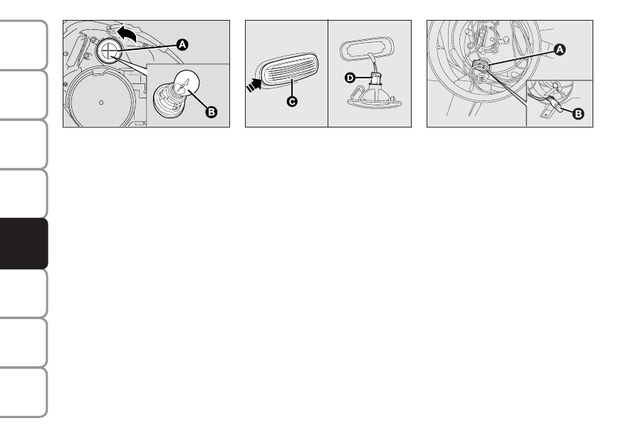
DIRECTION INDICATORS

Front fig. 22

To change the bulb, proceed as fol-

lows:
❒ turn the bulb holder anticlockwise

and pull it out;

❒ remove the bulb by pushing it

slightly and turning it in an anti-

clockwise direction (bayonet

mount);

❒ replace the bulb;
❒ refit the bulb holder by turning it

clockwise and locking it properly.

Side fig. 23

To change the bulb, proceed as fol-

lows:
❒ lever in the point shown by the ar-

row in order to compress the fas-

tening spring and extract the unit

C;

❒ turn the bulb holder anticlock-

wise, extract the clipped bulb and

replace it;

❒ refit the bulb holder  in the lens,

then position the assembly to the

unit making sure that the fastening

clip clicks.

SIDE LIGHTS fig. 24

To change the bulbs, proceed as fol-

lows:
❒ remove the protective cover releas-

ing the relevant catch;

❒ remove snap-fitted bulb holder A,

remove the bulb Band replace it;

❒ refit the snap-fitted bulb holder A;
❒ refit the protective caps correctly

after replacing.

fig. 23

L0C0148m

fig. 22

L0D0169m

fig. 24

L0D0520m

-------------------------------------------------------------------------------------------------------------------------------------------------------------

153

W

A

RNING

LIGHTS AND

MESSAGES

MAINTENANCE

AND CARE

TECHNICAL

SPECIFICA-

TIONS

INDEX

DASHBOARD

AND

CONTROLS

SAFETY

ST

AR

TING

AND DRIVING

IN AN

EMERGENCY

FRONT FOG LIGHTS fig. 25
(for versions/markets, where provided)

Contact a Lancia Dealership to re-

place the front fog lights.

fig. 25

L0D0406m

REAR LIGHT CLUSTERS 

LEDs are used for the taillights and

the brake lights. Contact a Lancia

Dealership in case of faults.

To change a direction indicator bulb,

proceed as follows:
❒ open the tailgate;
❒ turn the fastening device anti-

clockwise (left flap) or clockwise

(right flap) and remove the cover;

❒ disconnect the electric connector

C;

❒ loosen the two fastening nuts B;
❒ to remove the light cluster, pull

perpendicularly using the handle

present on the light cluster body;

❒ press the bulb fastening tabs and

extract the bulb;

❒ remove the bulb  by pushing it

slightly and turning it anticlock-

wise;

❒ insert the bulb holder, making sure

that the two tabs are correctly fas-

tened; insert the light cluster inside

the housing and connect the elec-

tric connector C; fasten the two

nuts B; fasten the cover making

sure that the tabs are inserted in the

seat and turn the fastening device

anticlockwise (left flap) or clock-

wise (right flap) to secure it.  

fig. 26

L0D0187m

fig. 27

L0D0188m

-------------------------------------------------------------------------------------------------------------------------------------------------------------

154

W

A

RNING

LIGHTS AND

MESSAGES

MAINTENANCE

AND CARE

TECHNICAL

SPECIFICA-

TIONS

INDEX

DASHBOARD

AND

CONTROLS

SAFETY

ST

AR

TING

AND DRIVING

IN AN

EMERGENCY

THIRD BRAKE LIGHTS

The third brake light fits LEDs. Con-

tact a Lancia Dealership in case of

faults.

fig. 28

L0D0407m

NUMBER PLATE LIGHTS 
fig. 29a

To change the bulbs, proceed as fol-

lows:
❒ apply pressure to the point shown

by the arrow and remove lens A;

❒ change the bulb releasing it from

the side contacts and making sure

the new bulb is correctly fastened

between the contacts;

❒ withdraw the transparent cover as-

sembly.

fig. 29/a

L0D0357m

fig. 29/b

L0D0426m

fig. 29/c

L0D0427m

REAR FOG LIGHTS fig. 29/b

Go to a Lancia Dealership to replace

the rear fog light.

REVERSING LIGHTS fig. 29/c

Go to a Lancia Dealership to replace

the reversing light.

-------------------------------------------------------------------------------------------------------------------------------------------------------------

155

W

A

RNING

LIGHTS AND

MESSAGES

MAINTENANCE

AND CARE

TECHNICAL

SPECIFICA-

TIONS

INDEX

DASHBOARD

AND

CONTROLS

SAFETY

ST

AR

TING

AND DRIVING

IN AN

EMERGENCY

fig. 30

L0D0193m

fig. 31

L0D0194m

REPLACING AN
INTERIOR BULB

For the type of bulb and power rat-

ing, see “When needing to change a

bulb”.

FRONT CEILING LIGHT 
fig. 30-31

To change the bulbs, proceed as fol-

lows:
❒ operate in the points shown by the

arrows and remove light A;

❒ open the protection lid B;
❒ replace bulbs releasing them

from the side contacts; make sure

that new bulbs are correctly

clamped between contacts;

❒ close the lid and secure light A

into its housing locking it properly.

REAR CEILING LIGHT 
fig. 32-33

To change the bulbs, proceed as fol-

lows:
❒ operate in the points shown by the

arrows and remove light D;

❒ open the protection lid E;

fig. 32

L0D0195m

❒ change the bulb releasing it from

the side contacts and making sure

the new bulb is correctly fastened

between the contacts;

❒ close the protection lid and se-

cure light into its housing lock-

ing it properly.

fig. 33

L0D0196m

-------------------------------------------------------------------------------------------------------------------------------------------------------------

156

W

A

RNING

LIGHTS AND

MESSAGES

MAINTENANCE

AND CARE

TECHNICAL

SPECIFICA-

TIONS

INDEX

DASHBOARD

AND

CONTROLS

SAFETY

ST

AR

TING

AND DRIVING

IN AN

EMERGENCY

BOOT LIGHT fig. 34

To change the bulb, proceed as fol-

lows:
❒ open the tailgate;
❒ remove the light levering in the

point shown by the arrow.

❒ open the protection and replace

the snap-fitted bulb;

❒ re-close the protective cover on

the lens;

❒ refit the light inserting it in its

correct position firstly on one end

and then on the other until it

clicks into place.

fig. 34

L0D0197m

REPLACING FUSES

INTRODUCTION fig. 35

The fuse is a protective device for the

electric system: it comes into action

(i.e. it cuts off) mainly due to a fault

or improper action on the system.

Check the efficiency of the corre-

sponding fuse when a device does not

work: the conducting element must

not be interrupted. If it is, replace the

blown fuse with another with the

same amperage (same colour).

B: intact fuse

C: fuse with damaged filament.

Use the tongs in the fusebox on the

dashboard to change a fuse.

fig. 35

L0D0198m

If a fuse blows again, con-
tact a Lancia Dealership.

WARNING

Never replace a fuse with
another of higher amper-
age: FIRE RISK. 

If a general protection fuse
(MEGA-FUSE, MIDI-

FUSE, MAXI-FUSE) blows, con-
tact your Lancia Dealership

WARNING

Remove the key from the
ignition switch and switch

off all loads before replacing a
fuse.

WARNING

If a general protection fuse
for safety systems (air bag

system, braking system), power
unit systems (engine system, trans-
mission system) or steering system
is triggered, contact a Lancia
Dealership.

WARNING

-------------------------------------------------------------------------------------------------------------------------------------------------------------

157

W

A

RNING

LIGHTS AND

MESSAGES

MAINTENANCE

AND CARE

TECHNICAL

SPECIFICA-

TIONS

INDEX

DASHBOARD

AND

CONTROLS

SAFETY

ST

AR

TING

AND DRIVING

IN AN

EMERGENCY

FUSE LOCATION

The fuses are contained in two dash-

boards, one  on the dashboard on the

left hand of the steering column and

one in the engine compartment next

to the battery.

Dashboard fusebox fig. 37

To access the dashboard fusebox, loosen

the fastening screws  A-fig. 36 and then

remove the protection panel  B.

L0D0200m

fig. 36

L0D0424m

fig. 37

-------------------------------------------------------------------------------------------------------------------------------------------------------------

158

W

A

RNING

LIGHTS AND

MESSAGES

MAINTENANCE

AND CARE

TECHNICAL

SPECIFICA-

TIONS

INDEX

DASHBOARD

AND

CONTROLS

SAFETY

ST

AR

TING

AND DRIVING

IN AN

EMERGENCY

Fusebox next to the battery 
fig. 39

To gain access to the fuses in the fuse-

box next to the battery, remove the

protection cover B-fig. 38.

L0D0409m

fig. 38

L0D0201m

fig. 39

If you need to wash the en-
gine compartment, take
care not to directly hit the
engine compartment control

unit with the water jet.

-------------------------------------------------------------------------------------------------------------------------------------------------------------

159

W

A

RNING

LIGHTS AND

MESSAGES

MAINTENANCE

AND CARE

TECHNICAL

SPECIFICA-

TIONS

INDEX

DASHBOARD

AND

CONTROLS

SAFETY

ST

AR

TING

AND DRIVING

IN AN

EMERGENCY

FUSE TABLE

Dashboard fusebox fig. 37

USERS

FUSE

AMPERES

Right dipped headlamp

F12

7.5

Left dipped headlamp/headlamp alignment corrector

F13

7.5

Engine compartment fuse box relay coils, body computer

F31

7.5

Rear left electric window

F33

20

Rear right electric window

F34

20

+15 Signal from switch on brake pedal for control units, reverse light/s, flow meter (MultiJet versions, 
Start&Stop excluded), heater plug control unit (1.3 MultiJet EURO 5 versions), clutch control (Start&Stop), 
brake servo (Start&Stop) and water sensor in diesel (*)

F35

7.5

Boot unlocking 

F36

10

+15 Brake lights, instrument panel (*)

F37

7.5

Door lock, fuel flap actuator

F38

20

+30 Radio, navigator, Blue&Me™ system, electric window control unit, tyre pressure control unit, 
climate control, EOBD diagnosis socket (*)

F39

10

Heated rear window 

F40

30

Heated electric mirrors

F41

7.5

Windscreen wiper, windscreen/rear window washer

F43

30

Cigar lighter / current socket on tunnel

F44

15

Heated front seats

F45

15

Luggage compartment current socket

F46

15

Driver's side front electric window

F47

20

Passenger 's side front electric window

F48

20

+15 Controls on the steering wheel, lighting for sun roof controls, left and centre dashboards, rain/dusk sensor, 
electric mirrors, heated front seat controls (*)

F49

7.5

+15 Navigator, radio setup, Blue&Me™ system, parking sensors, tyre pressure control unit, power window 
control unit, electric mirrors, climate control system knob lighting and ECO button, Cruise Control, voltage 
stabiliser (Start&Stop) (*)

F51

7.5

Rear window wiper

F52

15

+30 Instrument panel, rear fog lamp/s (*)

F53

7.5

(*) +30 = battery direct positive pole (not ignition switch)

+15 = positive pole ignition switch 

-------------------------------------------------------------------------------------------------------------------------------------------------------------

160

W

A

RNING

LIGHTS AND

MESSAGES

MAINTENANCE

AND CARE

TECHNICAL

SPECIFICA-

TIONS

INDEX

DASHBOARD

AND

CONTROLS

SAFETY

ST

AR

TING

AND DRIVING

IN AN

EMERGENCY

Fusebox in engine compartment fig. 39

USERS

FUSE

AMPERES

Horn

F10

15

Right beam

F14

7.5

Left beam

F15

7.5

Compressor

F19

7.5

Starting system (Start&Stop)

F20

30

Fuel pump

F21

15

Fog lights

F30

15

(*) +30 = battery direct positive pole (not ignition switch)

+15 = positive pole ignition switch 

Optional fusebox (on auxiliary bracket) fig. 37

USERS

FUSE

AMPERES

+30 External radio amplifier (*)

F54

15

+30 Sunroof (*)

F58

20

(*) +30 = battery direct positive pole (not ignition switch)

+15 = positive pole ignition switch 

-------------------------------------------------------------------------------------------------------------------------------------------------------------

161

W

A

RNING

LIGHTS AND

MESSAGES

MAINTENANCE

AND CARE

TECHNICAL

SPECIFICA-

TIONS

INDEX

DASHBOARD

AND

CONTROLS

SAFETY

ST

AR

TING

AND DRIVING

IN AN

EMERGENCY

IF THE BATTERY 
IS FLAT

IMPORTANT The battery recharging

procedure is provided as an example

only. You are recommended to go to a

Lancia Dealership to have this oper-

ation performed.

Low amperage slow recharging for

approximately 24 hour is advised. A

long charge could damage the battery.

Proceed as follows to charge the bat-

tery:
❒ disconnect battery negative termi-

nal;

❒ connect the charger cables to the

battery terminals, observing the

poles;

❒ turn on the charger;
❒ when you have finished, turn the

charger off before disconnecting the

battery;

❒ reconnect battery negative termi-

nal.

IMPORTANT If the car is equipped

with an alarm system, disarm the

alarm system by means of the remote

control (see “Alarm” paragraph in

“Dashboard and controls”).

LIFTING THE CAR

If the car is to be lifted, go to a Lan-

cia Dealership which is equipped with

the arm hoist or workshop lift. 

Lift the car exclusively by positioning

the jack arms or the shop jack in the

points shown in the figure.

Battery fluid is poisonous
and corrosive: avoid con-

tact with your skin and eyes. The
battery recharging operation must
be performed in a ventilated placed
away from naked flames o possi-
ble sources of sparks to avoid the
risk of explosion and fire.

WARNING

Never attempt to recharge
a frozen battery: defrost it

first to prevent the risk of explo-
sion. If a battery was frozen, have
it inspected by specialised person-
nel before recharging to check that
the internal elements are not dam-
aged and that the casing is not
cracked causing the risk of leakage
of poisonous, corrosive gas.

WARNING

fig. 40

L0D0486m

-------------------------------------------------------------------------------------------------------------------------------------------------------------

162

W

A

RNING

LIGHTS AND

MESSAGES

MAINTENANCE

AND CARE

TECHNICAL

SPECIFICA-

TIONS

INDEX

DASHBOARD

AND

CONTROLS

SAFETY

ST

AR

TING

AND DRIVING

IN AN

EMERGENCY

TOWING THE CAR

The car is provided with two tow

rings: use the shorter one on the front

and the longer one on the back.

The tow rings are arranged inside the

tool container. 

The arrangement of the rear ring

(long) inside the spare wheel and in-

side the automatic Fix & Go quick re-

pair kit are shown in fig. 41 and in

fig. 42 respectively.

On cars with Dual Function System

gearbox, make sure that the gearbox

is in neutral (check that the car can

move when pushed) and tow as a nor-

mal car with mechanical gearbox.

If the gearbox cannot be placed in

neutral, do not tow the vehicle and

contact a Lancia Dealership.

fig. 41

L0D0342m

fig. 42

L0D0369m

REMOVING THE TOW HITCH
CAPS

To avoid damaging the cap A-fig. 43,

proceed as follows:
❒ take the screwdriver from the tool

container;

❒ insert the screwdriver in the slot B

on the cap;

❒ rest your thumb on the cap to

avoid damage (see figure);

❒ extract the cap (without turning

it) perpendicular to the support-

ing surface fig. 44.

fig. 43

L0D0250m

-------------------------------------------------------------------------------------------------------------------------------------------------------------

163

W

A

RNING

LIGHTS AND

MESSAGES

MAINTENANCE

AND CARE

TECHNICAL

SPECIFICA-

TIONS

INDEX

DASHBOARD

AND

CONTROLS

SAFETY

ST

AR

TING

AND DRIVING

IN AN

EMERGENCY

fig. 44

L0D0251m

FASTENING THE TOW RING

Proceed as follows:
❒ take the tow hook from the sup-

port;

❒ tighten the ring on the rear fig. 46

or front fig. 45 threaded pin.

fig. 45

L0D0487m

fig. 46

L0D0205m

The power brakes and
power steering will not

work while the car is being towed.
More effort on the brake pedal and
steering wheel will therefore be re-
quired. Do not use wires for tow-
ing. Do not jerk. Make sure not to
damage parts in contact with the
car while towing. Respect the spe-
cific rules of the Highway Code
when towing the car specifically in
relation to the towing device and
the behaviour to maintain on the
road.

WARNING

Before towing, turn the key
to MAR and then to STOP

without extracting it. The steering
column will automatically lock
when the key is removed and the
wheels cannot be steered.

WARNING

Do not start the engine
while towing the car.

WARNING

-------------------------------------------------------------------------------------------------------------------------------------------------------------

164

W

A

RNING

LIGHTS AND

MESSAGES

MAINTENANCE

AND CARE

TECHNICAL

SPECIFICA-

TIONS

INDEX

DASHBOARD

AND

CONTROLS

SAFETY

ST

AR

TING

AND DRIVING

IN AN

EMERGENCY

Before fitting the hook, clean
accurately its threaded seat.

Before starting to tow, make sure to
have tighten the hook.

WARNING

The front and rear tow
hooks must only be used for
emergency situations on the
road. The vehicle may be

towed for short distances when a
dedicated device is used in compli-
ance with the Highway Code (rigid
bar), in order to move the vehicle on
the road in preparation for towing
by a tow truck Tow hooks MUST
NOT be used to tow vehicles off the
road or where there are obstacles
and/or for towing operations using
cables or other non-rigid devices.
Respecting the above conditions,
towing must only take place with
two vehicles (one towing, the other
towed) travelling as far as possible
in alignment along the same centre-
line.

-------------------------------------------------------------------------------------------------------------------------------------------------------------

165

W

A

RNING

LIGHTS AND

MESSAGES

TECHNICAL

SPECIFICA-

TIONS

INDEX

DASHBOARD

AND

CONTROLS

SAFETY

ST

AR

TING

AND DRIVING

IN AN

EMERGENCY

MAINTENANCE

AND CARE

MAINTENANCE AND CARE

SCHEDULED SERVICING ............................... 166

SERVICE SCHEDULE

................................... 167

YEARLY INSPECTION PLAN   ......................... 169

ADDITIONAL INTERVENTIONS ..................... 169

CHECKING THE LEVELS ............................... 171

FUEL FILTER (green filter) .............................. 177

BATTERY  ......................................................... 177

WHEELS AND TYRES ..................................... 179

RUBBER HOSES  .............................................. 180

WINDSCREEN/REAR WINDOW 

WIPER/WASHER  ............................................. 181

BODYWORK .................................................... 182

INTERIORS ....................................................... 185

-------------------------------------------------------------------------------------------------------------------------------------------------------------

166

W

A

RNING

LIGHTS AND

MESSAGES

TECHNICAL

SPECIFICA-

TIONS

INDEX

DASHBOARD

AND

CONTROLS

SAFETY

ST

AR

TING

AND DRIVING

IN

EMERGENZA

MAINTENANCE

AND CARE

SCHEDULED
SERVICING

Correct maintenance is essential for

ensuring long car life under the best

conditions.

This is why Lancia has planned a se-

ries of checks and maintenance oper-

ations every 20,000 km.

Scheduled servicing will not however

fully cover all of the need of your car:

It is however important to remember

that scheduled servicing does not

completely cover all the car’s require-

ments: also in the initial period before

20.000 km service coupon and later,

between one coupon and another, or-

dinary care is still required such as for

example routine check and topping

up the level of fluids, tyre pressure

check, etc.

IMPORTANT Scheduled service

coupons are required by the manu-

facturer. Default may cancel the war-

ranty.

Scheduled Servicing is performed by

all Lancia Dealerships at pre-estab-

lished times.

If during each operation, in addition

to the ones programmed, the need

arises for further replacements or re-

pairs, these may only be carried out

with the explicit agreement of the

Customer. 

IMPORTANT You are advised to con-

tact Lancia Dealership in the event of

any minor operating faults, without

waiting for the next service coupon.

If your car is used frequently for tow-

ing, the interval between one service

coupon and the other must be re-

duced.

-------------------------------------------------------------------------------------------------------------------------------------------------------------

167

W

A

RNING

LIGHTS AND

MESSAGES

TECHNICAL

SPECIFICA-

TIONS

INDEX

DASHBOARD

AND

CONTROLS

SAFETY

ST

AR

TING

AND DRIVING

IN AN

EMERGENCY

MAINTENANCE

AND CARE

SERVICE SCHEDULE

Thousands of kilometres

Check tyre condition/wear and, if necessary, adjust pressure 

Check lighting system operation 
(headlights, direction indicators, hazard lights, boot, 
passenger compartment, oddment compartments, 
instrument panel warning lights, etc.)

Check windscreen wiper/washer 
(nozzle direction and blade wear)

Check conditions and wear of front disk brake pads and 
operation of pad wear indicator

Check rear drum brake linings and wear

Check condition and wear of rear brake discs
(for versions/markets, where provided)

Visually inspect the condition of: exterior bodywork, 
underbody protection, flexible and stiff piping 
(exhaust, fuel feed, brakes), rubber parts 
(boots, sleeves, bushings, etc.)

Check cleanness of locks, bonnet and boot and lever 
cleanness and lubrication

Check tension and conditions of various accessory drive belts 
(except for engines with automatic take-up devices)

Inspect conditions of various drive belts

Check and adjust tappets (1.4

8V

versions)

Check battery charge status and possibly recharge

20

40

60

80

100

120

140

160 180

-------------------------------------------------------------------------------------------------------------------------------------------------------------


Content      ..     8      9      10      11     ..