Lancia MUSA. Service Manual - part 9
 

  Index      Manuals     Lancia MUSA. Service Manual


Search            copyright infringement  


Content      ..     7      8      9      10     ..


Lancia MUSA. Service Manual - part 9


136

W

A

RNING

LIGHTS AND

MESSAGES

MAINTENANCE

AND CARE

TECHNICAL

SPECIFICA-

TIONS

INDEX

DASHBOARD

AND

CONTROLS

SAFETY

ST

AR

TING

AND DRIVING

IN AN

EMERGENCY

OPENING/CLOSING
THE DOORS

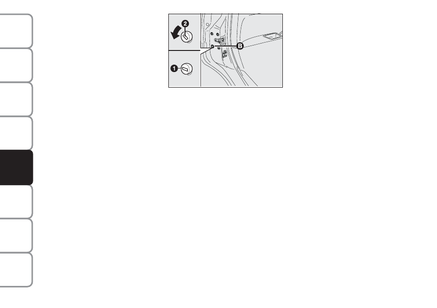
Emergency device for opening
the doors from the outside

The doors are provided with a device

for locking all the door using the lock

in case of a power fault.

Proceed as follows to lock the doors: 
❒ insert the ignition key in lock 

B-fig. 1

❒ turn the device to position  and

close the door. 

fig. 1

L0D0247m

STARTING 
THE ENGINE

JUMP STARTING

If the battery is flat, the engine may

be started using an auxiliary battery

with the same capacity or a little

higher than the flat one.

Proceed as follows to start the engine:
❒ connect the positive terminals (+

sign near terminal) of both batter-

ies using a lead;

❒ With a second lead, connect the

negative terminal (–) of the auxil-

iary battery to an earthing point E

on the engine or the gearbox of the

car to be started;

❒ start the engine;
❒ when the engine has been started,

remove the leads reversing the or-

der above. If engine fails to start

again do not attempt any further

and call a Lancia Dealership.

To reopen the doors:
❒ insert the key in the lock on dri-

ver’s side and turn it anticlockwise 

❒ open the driver’s door 
❒ operate the door levers from the

inside of the vehicle for the re-

maining doors.

-------------------------------------------------------------------------------------------------------------------------------------------------------------

137

W

A

RNING

LIGHTS AND

MESSAGES

MAINTENANCE

AND CARE

TECHNICAL

SPECIFICA-

TIONS

INDEX

DASHBOARD

AND

CONTROLS

SAFETY

ST

AR

TING

AND DRIVING

IN AN

EMERGENCY

If after a few attempts the engine does

not start, do not insist but contact the

nearest Lancia Dealership.

IMPORTANT Never connect the neg-

ative terminals of the two batteries di-

rectly: sparks could ignite explosive

gas released from the battery. If the

auxiliary battery is installed on an-

other car, prevent accidental contact

between metallic parts of the two cars.

fig. 2

L0D0396m

This procedure must be
performed by expert per-

sonnel because incorrect actions
may cause electrical discharge of
considerable intensity. Further-
more, battery fluid is poisonous
and corrosive: avoid contact with
your skin and eyes. Keep naked
flames away from the battery. No
smoking. Do not cause sparks.

WARNING

Never use a rapid battery
charger to jump start the
engine: this could damage
the electronic systems and

the engine ignition and injection
control units. 

-------------------------------------------------------------------------------------------------------------------------------------------------------------

138

W

A

RNING

LIGHTS AND

MESSAGES

MAINTENANCE

AND CARE

TECHNICAL

SPECIFICA-

TIONS

INDEX

DASHBOARD

AND

CONTROLS

SAFETY

ST

AR

TING

AND DRIVING

IN AN

EMERGENCY

BUMP STARTING

Never bump start the engine by push-

ing, towing or driving downhill. This

could cause a flow of fuel into the cat-

alytic converter and damage it beyond

repair.

IMPORTANT Remember that the

brake servo and the electric power

steering system are not activated un-

til the engine is started, a greater ef-

fort will therefore be required to press

the brake pedal or turn the steering

wheel.

Indicate that the car is
standing according to the

laws in force: emergency lights, re-
fracting warning triangle, etc. Pas-
sengers should leave the car, partic-
ularly if it is very loaded, and wait
for the wheel to be changed away
from on-coming traffic. Arrange
wedges or other suitable material
under the wheels to block the car on
slopes or rough roads.

WARNING

FIX & GO Automatic 
QUICK TYRE
REPAIR KIT

(for versions/markets, where provided)

The automatic Fix & Go quick tyre

repair kit fig. 3 is placed in the boot.

The kit includes:
❒ bottle containing sealer and fit-

ted with:

– filling pipe B;

– an adhesive label with the

message “max. 80 km/h” to be

apply in a position clearly visi-

ble by the driver (on the dash-

board) after repairing the tyre;

❒ instruction brochure (see fig. 4), to

be used for prompt and proper use

of the quick repair kit and to be

then handed to the personnel

charged with handling the treated

tyre;

-------------------------------------------------------------------------------------------------------------------------------------------------------------

139

W

A

RNING

LIGHTS AND

MESSAGES

MAINTENANCE

AND CARE

TECHNICAL

SPECIFICA-

TIONS

INDEX

DASHBOARD

AND

CONTROLS

SAFETY

ST

AR

TING

AND DRIVING

IN AN

EMERGENCY

fig. 3

L0D0361m

fig. 4

L0D0362m

❒ compressor including gauge and

connections;

❒ a pair of protection gloves located

in the side space of the compressor;

❒ adapters for inflating different ele-

ments.

The quick repair kit container in the

boot under the mat also contains the

screwdriver and tow rings.

Give the instruction book-
let to the tyre repair work-

shop personnel.

WARNING

IMPORTANT Do not use the quick

repair kit if the tyre was damaged by

running on a flat.

IMPORTANT INFORMATION:

The sealing fluid of the quick tyre re-

pair kit is effective with external tem-

peratures between 20 °C –and 

+50 °C. 

The sealing fluid will expire. 

The kit cannot be used to
repair damage to the tyre

sidewall. Do not use the quick re-
pair kit if the tyre was damaged by
running on a flat.

The damage cannot be repaired
with the kit if the wheel rim is
damaged (deformation of the chan-
nel causing leakage of air). Do not
remove the foreign body (screw or
nail) from the tyre.

Do not operate the compressor for
longer than 20 consecutive min-
utes. Risk of overheating. The
quick repair kit is not suitable for
definitive repairs. The tyres may
only be repaired temporarily.

WARNING

In the event of a puncture
caused by foreign bodies,
the kit may be used to re-
pair tyres showing dam-

ages on the track or shoulder up to
max 4 mm diameter. 

Replace the cylinder con-
taining the sealant after the
expiration date. Dispose of
the cylinder and the sealant

liquid properly. Dispose according to
the national and local laws in force.

-------------------------------------------------------------------------------------------------------------------------------------------------------------

140

W

A

RNING

LIGHTS AND

MESSAGES

MAINTENANCE

AND CARE

TECHNICAL

SPECIFICA-

TIONS

INDEX

DASHBOARD

AND

CONTROLS

SAFETY

ST

AR

TING

AND DRIVING

IN AN

EMERGENCY

INFLATION PROCEDURE 
❒ Ensure that the handbrake is

up. Undo the tyre valve cap, ex-

tract the inflation tube A-fig. 5 and

tighten the ring nut on the tyre

valve;

fig. 5

L0D0484m

Put on the protection
gloves provided together

with quick tyre repair kit.

WARNING

The cylinder contains
ethyl glycol. Contains la-

tex: may cause an allergic reaction.
Harmful if swallowed. Irritant for
the eye. May cause sensitization by
inhalation or contact. Avoid con-
tact with your eyes, skin and
clothes. In the event of contact,
wash immediately with plenty of
water. Do not induce vomit if swal-
lowed. Rinse your mouth and
drink plenty of water. Call a doc-
tor immediately. Keep away from
children. The product must not be
used by asthmatics. Do not breath
in the vapours during insertion and
suction. Call a doctor immediately
if allergic reactions are noted.
Store the cylinder in the specific
compartment, away from sources
of heat.

WARNING

❒ make sure that the switch  D-

fig. 6 of the compressor is in posi-

tion (off), start the engine, insert

plug A-fig. 7 into the cigar lighter

(or 12V socket) and operate the

compressor by taking the switch

to position (on). Inflate the

tyre to the pressure specified in the

“Inflation pressure” paragraph,

“Technical Specifications” chap-

ter. 

fig. 6

L0D0364m

fig. 7

L0D0177m

-------------------------------------------------------------------------------------------------------------------------------------------------------------

141

W

A

RNING

LIGHTS AND

MESSAGES

MAINTENANCE

AND CARE

TECHNICAL

SPECIFICA-

TIONS

INDEX

DASHBOARD

AND

CONTROLS

SAFETY

ST

AR

TING

AND DRIVING

IN AN

EMERGENCY

For a more accurate reading,

check pressure gauge F-fig. 6 with

the compressor off; 

❒ if after 5 minutes it is still impossi-

ble to reach at least 1.5 bar, disen-

gage compressor from valve and

current outlet, then move the car

forth for approx. ten metres in or-

der to distribute the sealing fluid

inside the tyre evenly, then repeat

the inflation operation;

❒ If after this operation it is still im-

possible after 5 minutes to reach at

least 1.8 bar, do not start driving

since the tyre is excessively dam-

aged and the quick tyre repair kit

cannot guarantee suitable sealing,

contact Lancia Dealership.

fig. 8

L0D0485m

Apply the adhesive label in
a position clearly visible

by the driver as a reminder that
the tyre has been treated with the
quick repair kit. Drive carefully,
particularly on bends. Do not ex-
ceed 80 km/h. Do not accelerate or
brake suddenly.

WARNING

Stop if the pressure has
dropped to less than 1.8

bars: the automatic Fix & Go quick
repair kit cannot work properly
because the tyre is excessively
damaged. Go to a Lancia Dealer-
ship.

WARNING

❒ if reaching the tyre pressure speci-

fied in paragraph “Inflation pres-

sure” in section “Technical Specifi-

cations”, start driving immediately;

❒ after driving for about 10 minutes

stop and check again the tyre pres-

sure; pull up the handbrake;

❒ if at least 1.8 bar pressure is read,

restore proper pressure (with en-

gine running and handbrake on)

and restart;

❒ drive with the utmost care to the

nearest Lancia Dealership.

FOR CHECKING AND
RESTORING PRESSURE ONLY

The compressor may also be used for

restoring pressure only. Release the

quick coupling and connect directly

to the tyre valve; in this way, the

cylinder will not be connected to the

compressor and no sealant will be in-

jected.

-------------------------------------------------------------------------------------------------------------------------------------------------------------

142

W

A

RNING

LIGHTS AND

MESSAGES

MAINTENANCE

AND CARE

TECHNICAL

SPECIFICA-

TIONS

INDEX

DASHBOARD

AND

CONTROLS

SAFETY

ST

AR

TING

AND DRIVING

IN AN

EMERGENCY

CANISTER REPLACEMENT
PROCEDURE

To replace the canister, proceed as fol-

lows:
❒ disconnect connection A-fig. 9;
❒ turn anticlockwise the canister to

replace and raise it;

❒ fit the new canister and turn it

clockwise;

❒ connect to the canister and in-

sert the transparent tube  in the

specific compartment.

fig. 9

L0D0368m

Remember to inform the
workshop that the tyre has

been treated with a quick repair
kit. Give the instruction booklet to
the tyre repair workshop person-
nel.

WARNING

REPLACING
A WHEEL

GENERAL INSTRUCTIONS

Wheel changing and correct use of the

jack and spare wheel call for some

precautions as listed below.

IMPORTANT Refer to the instructions

in the previous chapter if the car is

equipped with “Fix&Go (quick tyre

repair kit)”. 

The spare wheel is specific
for your car. Do not use it

on cars of different models. Do not
use spare wheels of different mod-
els on your car. The space saver
spare wheel must only be used in
case of emergency. Use only for as
long as strictly necessary and drive
at a speed slower than 80 km/h. An
orange label is affixed on the spare
wheel summarising instructions
and limitations for use. Never re-
move or cover the label. Never ap-
ply a wheel cup on a space saver
spare. The following information
is provided in four languages on
the label: Warning! Suitable for
temporary use only! 80 km/h max!
Replace with a standard wheel as
soon as possible. Do not cover this
label.

WARNING

-------------------------------------------------------------------------------------------------------------------------------------------------------------

143

W

A

RNING

LIGHTS AND

MESSAGES

MAINTENANCE

AND CARE

TECHNICAL

SPECIFICA-

TIONS

INDEX

DASHBOARD

AND

CONTROLS

SAFETY

ST

AR

TING

AND DRIVING

IN AN

EMERGENCY

The driving features of the
car may change when a

space saver spare wheel is fitted.
Avoid sudden acceleration and
braking, sudden steering and fast
cornering. The total life of a space
saver spare wheel is approxi-
mately 3000 km, after which it
must be replaced by another wheel
of the same type. Never install a
traditional tyre on a space saver
spare wheel rim. Repair and refit
the standard wheel as soon as pos-
sible. Only one space saver spare
can be used at a time. Do not ap-
ply grease to the bolt threading be-
fore assembly: the bolts could come
loose unexpectedly.

WARNING

The jack may only be used
to replace wheels on the

car which it equips or other cars of
the same model. Never use the jack
for other purposes, such as lifting
other car models. Never use the
jack to carry out repairs under the
car. Incorrect positioning of the
jack may cause the car to fall. Do
not use the jack for loads higher
than those shown on the label.
Snow chains cannot be fitted on a
space saver spare wheel. There-
fore, if a front wheel (drive wheel)
is punctured and you need to use
snow chains, swap with a rear
wheel. In this way, you will have
two normal wheels on the front on
which you can fit snow chains and
solve the emergency.

WARNING

Incorrect wheel cup as-
sembly may cause it to

come off when the car is travelling.
Never tamper with the inflation
valve. Never introduce tools of any
kind between rim and tyre. Check
tyre and space saver spare wheel
pressure regularly referring to the
values shown in the “Technical
Specifications” chapter.

WARNING

-------------------------------------------------------------------------------------------------------------------------------------------------------------

144

W

A

RNING

LIGHTS AND

MESSAGES

MAINTENANCE

AND CARE

TECHNICAL

SPECIFICA-

TIONS

INDEX

DASHBOARD

AND

CONTROLS

SAFETY

ST

AR

TING

AND DRIVING

IN AN

EMERGENCY

To change a wheel proceed as follows:
❒ stop the car in a position so that it

is not a danger for on-coming traf-

fic and where you can replace the

wheel safely. The ground must be

flat and compact;

❒ turn the engine off and pull up the

handbrake.

❒ engage first gear or reverse;
❒ lift the boot mat;
❒ loosen the fastening device A-fig.

10;

❒ take out the tool container and

take it near to the wheel to be

changed;

❒ take the space saver spare wheel

C;

L0D0161m

fig. 10

Important notes:
❒ the jack cannot be repaired: replace

with an original spare part if dam-

aged;

❒ no tool other than its cranking de-

vice may be fitted on the jack.

-------------------------------------------------------------------------------------------------------------------------------------------------------------

145

W

A

RNING

LIGHTS AND

MESSAGES

MAINTENANCE

AND CARE

TECHNICAL

SPECIFICA-

TIONS

INDEX

DASHBOARD

AND

CONTROLS

SAFETY

ST

AR

TING

AND DRIVING

IN AN

EMERGENCY

fig. 11

L0D0397m

fig. 12

L0D0163m

❒ for cars fitting alloy rims, remove

the hub cap using the screwdriver

provided levering in groove  E-

fig. 11, as shown in the figure;

❒ loosen the bolts of the wheel to be

replaced by about one turn with the

wrench provided E-fig. 12; if the

car is fitted with alloy rims, shake

the car to facilitate removing the

rim from the wheel hub;

❒ operate the device F- fig. 13 to ex-

pand the jack, until the groove  G

on the upper part of the jack is

correctly inserted on the lower

edge of the body at indication  I

(at approximately 60 cm from the

front wheel centre or 80 cm from

the rear wheel centre);

❒ warn anybody nearby that the car

is about to be lifted. They must

stay clear and not touch the car

until it is back on the ground;

❒ fit the handle L-fig. 13 to operate

the jack and lift the car until the

wheel to be changed is several cen-

timetres off the ground;

❒ for versions with wheel cap, remove

the wheel cap after loosening the

three fastening bolts and finally

loosen the fourth bolt  and extract

the wheel;

❒ for versions with snap fitted wheel

cup, remove the cup being careful

not to damage it;

❒ make sure the contact surfaces be-

tween space saver spare wheel and

hub are clean so that the fastening

bolts will not come loose;

L0D0164m

fig. 13

-------------------------------------------------------------------------------------------------------------------------------------------------------------

146

W

A

RNING

LIGHTS AND

MESSAGES

MAINTENANCE

AND CARE

TECHNICAL

SPECIFICA-

TIONS

INDEX

DASHBOARD

AND

CONTROLS

SAFETY

ST

AR

TING

AND DRIVING

IN AN

EMERGENCY

fig. 14

L0D0165m

fig. 15

L0D0166m

❒ fit the space saver spare wheel

making the holes  M-fig. 14 coin-

cide with the corresponding cen-

tring pins N;

❒ using the wrench provided, tighten

the fastening bolts;

❒ turn the jack handle to lower the

car and remove the jack;

❒ use the wrench provided to fasten

the bolts completely in a criss-cross

fashion as shown in figure. 

REFITTING THE

STANDARD WHEEL

Following the procedure described

previously, raise the car and remove

the space saver spare wheel.

Versions with steel rims

Proceed as follows:
❒ Make sure the contact surfaces be-

tween standard wheel and hub are

clean so that the fastening bolts

will not come loose.

❒ Fit the standard wheel by inserting

the first bolt for two threads into

the hole closest to the inflation

valve.

❒ Fit the wheel cup making the

groove (on the cup) coincide with

the inflation valve and then insert

the other three bolts.

❒ For models with snap-on wheel

cup, press the edge of the cup with

the palm of your hands against the

wheel (do not hammer).

❒ Using the wrench provided,

tighten the fastening bolts.

❒ Lower the car and remove the

jack.

❒ using the wrench provided, fully

tighten the bolts in the sequence

shown previously in figure fig. 15.

IMPORTANT Incorrect assembly may

cause the cup to come off while trav-

elling.

-------------------------------------------------------------------------------------------------------------------------------------------------------------

147

W

A

RNING

LIGHTS AND

MESSAGES

MAINTENANCE

AND CARE

TECHNICAL

SPECIFICA-

TIONS

INDEX

DASHBOARD

AND

CONTROLS

SAFETY

ST

AR

TING

AND DRIVING

IN AN

EMERGENCY

Versions with alloy rims
❒ Check that the hub contact sur-

faces are clean;

❒ fit the normal wheel centring it on

the pins, lead in the fastening

screws and tighten them using the

wrench provided;

❒ lower the car and remove the jack;
❒ using the wrench provided, fully

tighten the bolts in the sequence

shown in fig. 15.

❒ snap fit the wheel cup on the hub.

When you have finished
❒ stow the spare wheel in the space

provided in the boot;

❒ fit the jack partially open in its

box forcing it lightly to prevent it

from vibrating when travelling;

❒ put the tools back into their places

in the container;

❒ arrange the container and tools in

the spare wheel and secure the fas-

tening device;

❒ rearrange the preformed boot

cover correctly. 

WHEN NEEDING
TO CHANGE A
BULB

GENERAL INSTRUCTIONS
❒ When a bulb is not working, check

that the corresponding fuse is in-

tact before replacing it: refer to the

“If a fuse blows” paragraph in this

chapter for fuse location.

❒ before changing a bulb check the

contacts for oxidation;

❒ burnt bulbs must be replaced by

others of the same type and power;

❒ always check the height of the

headlight beam after changing a

bulb.

Halogen lamps must be
handled holding the metal-
lic part only. Touching the
transparent part of the bulb

with your fingers may reduce the in-
tensity of the emitted light and even
compromise duration of the lamp it-
self.

-------------------------------------------------------------------------------------------------------------------------------------------------------------

148

W

A

RNING

LIGHTS AND

MESSAGES

MAINTENANCE

AND CARE

TECHNICAL

SPECIFICA-

TIONS

INDEX

DASHBOARD

AND

CONTROLS

SAFETY

ST

AR

TING

AND DRIVING

IN AN

EMERGENCY

Modifications or repairs to
the fuel feed system that

are not carried out properly or do
not take the system’s technical
specifications into account can
cause malfunctions leading to the
risk of fire.

WARNING

Halogen bulbs contain
pressurised gas which, if

broken, may cause small frag-
ments of glass to be projected out-
wards.

WARNING

BULB TYPES fig. 16

Various types of bulbs are fitted to

your car:

A All glass bulb: clipped into place.

Pull to extract.

B Bayonet bulbs: to remove this type

of bulb from its holder, press the

bulb and turn it anticlockwise.

C Cylindrical bulbs: release from the

contacts to extract.

D-E Halogen bulbs: release the fas-

tening clip from the correspond-

ing seat to remove the lamp.

L0D0178m

fig. 16

The taillights and the
third brake light fit LEDs.

Contact a Lancia Dealership in
case of faults. 

WARNING

IMPORTANT When the weather is cold

or damp or after hard rain or after

washing, the area of headlamps or rear

lights, may steam up and/or form drops

of condensation on the inside. This is a

natural phenomenon due to the differ-

ence in temperature and humidity be-

tween the inside and the outside of the

glass which does not indicate a fault

and does not compromise the normal

operation of lighting devices. The mist

disappears quickly turning the lights

on, starting from the centre of the dif-

fuser, extending progressively towards

the edges.

-------------------------------------------------------------------------------------------------------------------------------------------------------------

149

W

A

RNING

LIGHTS AND

MESSAGES

MAINTENANCE

AND CARE

TECHNICAL

SPECIFICA-

TIONS

INDEX

DASHBOARD

AND

CONTROLS

SAFETY

ST

AR

TING

AND DRIVING

IN AN

EMERGENCY

Bulbs

Figure ref. 

Type

Power

Main beam headlights

E

H1

55W

Dipped beam headlights  

E

H1

55W

Front sidelights  

A

W5W

5W

Front fog lights (for versions/markets, where provided)

E

H1

55W

Front direction indicators 

B

PY21W

21W

Side direction indicators  

A

WY5W

5W

Rear direction indicators  

B

PY21W

21W

Reversing lights 

B

P21W

21W

Rear fog lights 

B

P21W

21W

Number plate lights 

C

C5W

5W

Front ceiling light 

A

W5W 10W

Rear ceiling light

A

W5W  

10W

Rear ceiling lights (with sunroof)

A

W5W 5W 

Boot light 

A

W5W

5W

-------------------------------------------------------------------------------------------------------------------------------------------------------------

150

W

A

RNING

LIGHTS AND

MESSAGES

MAINTENANCE

AND CARE

TECHNICAL

SPECIFICA-

TIONS

INDEX

DASHBOARD

AND

CONTROLS

SAFETY

ST

AR

TING

AND DRIVING

IN AN

EMERGENCY

REPLACING
EXTERIOR BULBS

For the type of bulb and power rat-

ing, see “When needing to change a

bulb”.

FRONT LIGHT CLUSTER 

The front light clusters contain side

lights, dipped beam, main beam and

direction indicator bulbs.

Remove the protective caps to remove

the side lights, the dipped beam and

the main beam headlights.

The bulbs are arranged inside the

light cluster  fig. 17 as follows:

dipped beam headlights 

main beam headlights and Side-

lights

direction indicators

After replacing, refit the protective

caps and check that they are secured

well.

IMPORTANT Remove the engine

compartment fusebox B-fig. 18 to ac-

cess the left headlights cover (in di-

rection of travel) for replacement.

fig. 18

L0D0125m

fig. 17

L0D0157m

Before replacing bulbs,
wait for the engine to cool

down: RISK OF BURNS!

WARNING

-------------------------------------------------------------------------------------------------------------------------------------------------------------

151

W

A

RNING

LIGHTS AND

MESSAGES

MAINTENANCE

AND CARE

TECHNICAL

SPECIFICA-

TIONS

INDEX

DASHBOARD

AND

CONTROLS

SAFETY

ST

AR

TING

AND DRIVING

IN AN

EMERGENCY

DIPPED BEAM HEADLIGHTS
fig. 19

To replace the bulb, proceed as fol-

lows:
❒ remove the protective cap;
❒ disconnect the electrical connector 

A-fig. 19;

❒ release the bulb holder catch B, take

out the bulb and replace it;

❒ fit the new bulb, ensuring that the

outline of the metal part coincides

with the grooves on the curve of the

headlight. Then reconnect the elec-

trical connector B and refasten the

bulb holder catch A;

❒ after replacing the bulb, put the pro-

tective cap back into position.

MAIN BEAM HEADLIGHTS 
fig. 20

To replace the bulb, proceed as fol-

lows:
❒ remove the protective cap;
❒ disconnect the electric connector 

A-fig. 20;

❒ release the bulb holder catches B,

take out the bulb and replace it;

❒ fit the new bulb, ensuring that the

outline of the metal part coincides

with the grooves on the curve of the

headlight. Then reconnect the elec-

trical connector and refasten the

bulb holder catches A;

❒ after replacing the bulb, put the pro-

tective cap back into position.

fig. 20

L0D0159m

fig. 19

L0D0158m

-------------------------------------------------------------------------------------------------------------------------------------------------------------


Content      ..     7      8      9      10     ..