Rover 820, 825, 827. Repair Manual - part 3
assembly should be maintained, not only to
avoid excessive tyre wear, but also to avoid
wear in the steering and suspension
components. Wheel imbalance is normally
signified by vibration through the vehicle’s
bodyshell, although in many cases it is
particularly noticeable through the steering
wheel. Conversely, it should be noted that
wear or damage in suspension or steering
components may cause excessive tyre wear.
Out-of-round or out-of-true tyres, damaged
wheels and wheel bearing wear/
maladjustment also fall into this category.
Balancing will not usually cure vibration
caused by such wear.
15 Wheel balancing may be carried out with
the wheel either on or off the vehicle. If
balanced on the vehicle, ensure that the
wheel-to-hub relationship is marked in some
way prior to subsequent wheel removal, so
that it may be refitted in its original position.
22 Driveshaft rubber gaiter and
CV joint check
1
1 The driveshaft rubber gaiters are very
important, because they prevent dirt, water
and foreign material from entering and
damaging the constant velocity (CV) joints.
External contamination can cause the gaiter
material to deteriorate prematurely, so it’s a
good idea to wash the gaiters with soap and
water occasionally.
2 With the vehicle raised and securely
supported on axle stands, turn the steering
onto full-lock, then slowly rotate each front
wheel in turn. Inspect the condition of the
outer constant velocity (CV) joint rubber
gaiters, squeezing the gaiters to open out the
folds. Check for signs of cracking, splits, or
deterioration of the rubber, which may allow
the escape of grease, and lead to the ingress
of water and grit into the joint. Also check the
security and condition of the retaining clips.
Repeat these checks on the inner CV joints. If
any damage or deterioration is found, the
gaiters should be renewed as described in
Chapter 8.
3 At the same time, check the general
condition of the outer CV joints themselves,
by first holding the driveshaft and attempting
to rotate the wheels. Repeat this check on the
inner joints, by holding the inner joint yoke
and attempting to rotate the driveshaft.
4 Any appreciable movement in the CV joint
indicates wear in the joint, wear in the
driveshaft splines, or a loose driveshaft
retaining nut.
23 Exhaust system check
1
1 With the engine cold (at least three hours
after the vehicle has been driven), check the
complete exhaust system, from its starting
point at the engine to the end of the tailpipe.
Ideally, this should be done on a hoist, where
unrestricted access is available; if a hoist is
not available, raise and support the vehicle on
axle stands.
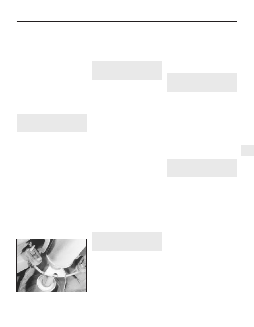
2 Check the pipes and connections for
evidence of leaks, severe corrosion, or
damage. Make sure that all brackets and
rubber mountings are in good condition, and
tight; if any of the mountings are to be
renewed, ensure that the replacements are of
the correct type (see illustration). Leakage at
any of the joints or in other parts of the system
will usually show up as a black sooty stain in
the vicinity of the leak. Note: Exhaust sealants
should not be used on any part of the exhaust
system upstream of the catalytic converter -
even if the sealant does not contain additives
harmful to the converter, pieces of it may
break off and foul the element, causing local
overheating.
3 At the same time, inspect the underside of
the body for holes, corrosion, open seams,
etc. which may allow exhaust gases to enter
the passenger compartment. Seal all body
openings with silicone or body putty.
4 Rattles and other noises can often be
traced to the exhaust system, especially the
rubber mountings. Try to move the system,
silencer(s) and catalytic converter. If any
components can touch the body or
suspension parts, secure the exhaust system
with new mountings.
24 Underbody and fuel/brake
line check
1
1 With the vehicle raised and supported on
axle stands or over an inspection pit,
thoroughly inspect the underbody and
wheelarches for signs of damage and
corrosion. In particular, examine the bottom of
the side sills, and any concealed areas where
mud can collect. Where corrosion and rust is
evident, press and tap firmly on the panel with
a screwdriver, and check for any serious
corrosion which would necessitate repairs. If
the panel is not seriously corroded, clean
away the rust, and apply a new coating of
underseal. Refer to Chapter 11 for more
details of body repairs.
2 At the same time, inspect the PVC-coated
lower body panels for stone damage and
general condition.
3 Inspect all of the fuel and brake lines on the
underbody for damage, rust, corrosion and
leakage. Also make sure that they are
correctly supported in their clips. Where
applicable, check the PVC coating on the
lines for damage.
25 Clutch operation and
hydraulic hose condition
check
1
1 Check the clutch pedal moves smoothly
and easily through its travel, and that the
clutch functions correctly, with no trace of slip
or drag.
2 Remove the closing panels under the facia
for access to the pedal and apply a few drops
of light oil to the pedal pivot. Refit the panel.
3 From within the engine compartment check
the condition of the fluid lines and hoses as
described in Section 8. Now have a look
under the front of the car at the clutch slave
cylinder. Check for signs of fluid leaks around
the rubber boot and check the security of the
linkage. Apply a few drops of oil to the
pushrod clevis pin and linkage.
26 Brake check
2
Note: For detailed photographs of the brake
system, refer to Chapter 9.
1 The work described in this Section should
be carried out at the specified intervals, or
whenever a defect is suspected in the braking
system. Any of the following symptoms could
indicate a potential brake system defect:
(a) The vehicle pulls to one side when the
brake pedal is depressed.
(b) The brakes make scraping or dragging
noises when applied.
(c) Brake pedal travel is excessive.
(d) The brake fluid requires repeated topping-
up.
2 A thorough inspection should be made to
confirm the thickness of the pad linings, as
follows.
3 Jack up the front or rear of the vehicle in
turn, and support it on axle stands.
4 For better access to the brake calipers,
remove the wheels.
5 Look through the inspection window in the
caliper, and check that the thickness of the
friction lining material on each of the pads is
not less than the recommended minimum
thickness given in the Specifications. Note:
Bear in mind that the lining material is normally
bonded to a metal backing plate.
6 If it is difficult to determine the exact
thickness of the pad linings, or if you are at all
Every 12 000 miles
1•21
23.2 Typical exhaust system rubber
mountings and brackets
1
1380 Rover 800 Series Remake