Rover 820, 825, 827. Repair Manual - part 2
Maintenance and servicing
1•5
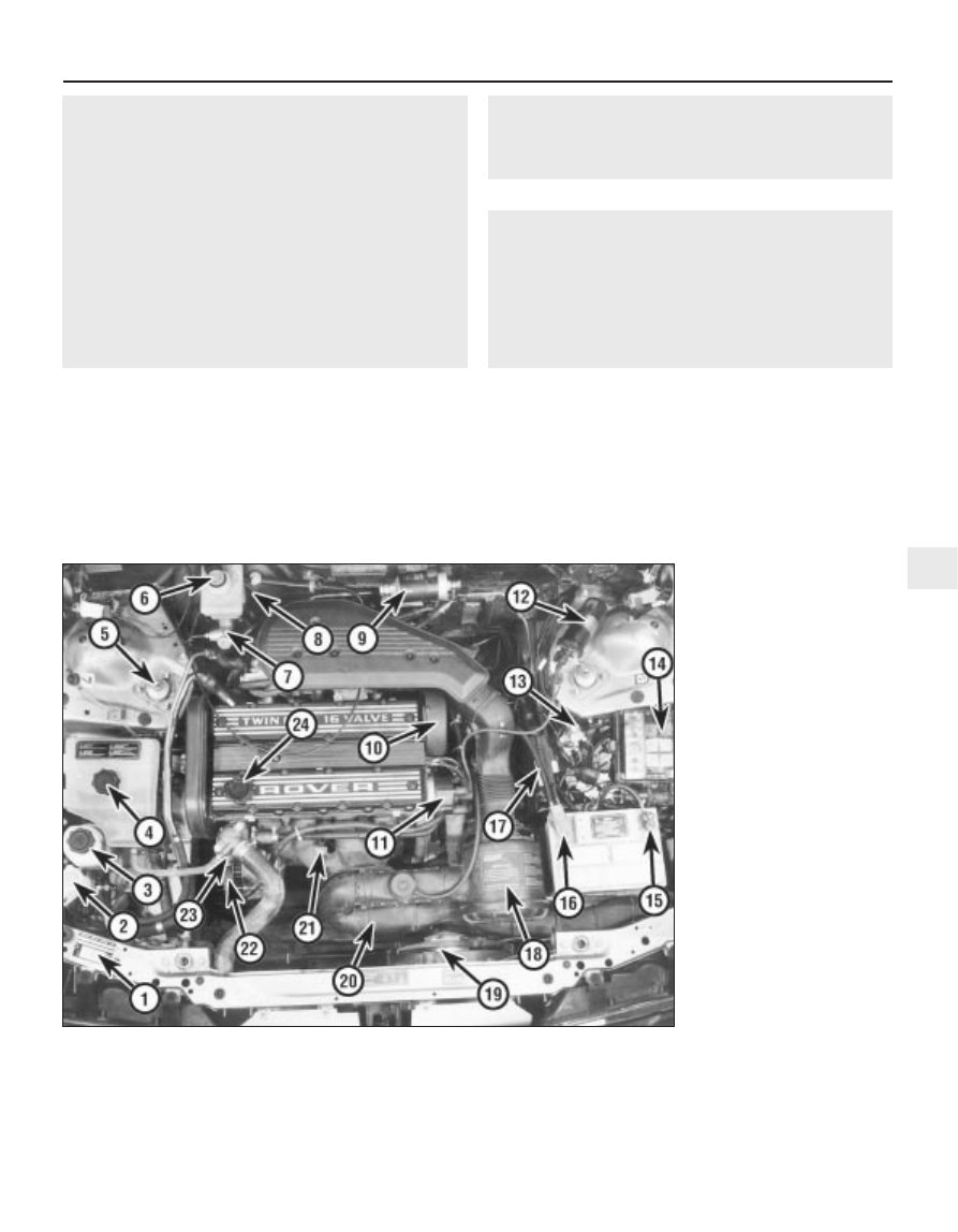
1 Vehicle identification plate
2 Screen washer reservoir filler
3 Power steering fluid reservoir
filler
4 Cooling system expansion tank
filler
5 Front shock absorber top
mounting
6 Brake and clutch fluid reservoir
filler
7 Brake master cylinder
8 Vacuum servo unit
9 Fuel filter
10 Power steering pump drivebelt
(early models)
11 Distributor cap
12 Ignition coil
13 Brake pressure reducing valve
14 Fuse and relay box
15 Battery negative terminal
16 Battery positive terminal
17 Ignition/fuel ECU
18 Air cleaner assembly
19 Radiator cooling fan
20 Air cleaner intake trunking
21 Engine oil dipstick
22 Alternator
23 Thermostat housing
24 Engine oil filler cap
1
1380 Rover 800 Series Remake
Every 24 000 miles (40 000 km) or
2 years, whichever occurs first
m
m
Renew the spark plugs (models with emission control
equipment) (Section 11).
m
m
Renew the air cleaner filter element (models with emission
control equipment) (Section 12).
m
m
Check the condition and tension of the timing belt
(Section 32).
m
m
Check the Positive Crankcase Ventilation system (Section 33).
m
m
Renew the fuel filter (Section 34).
m
m
Renew the automatic transmission fluid (Section 35).
m
m
Renew the brake fluid (Section 36).
m
m
Renew the manual transmission oil (Section 37).
m
m
Renew the coolant (Section 38).
Every 48 000 miles (80 000 km)
m
m
Renew the timing belt (Section 39).
Every 60 000 miles (100 000 km) or
5 years, whichever occurs first
m
m
Renew the braking system rubber seals (recommendation
only) (Section 40).
m
m
Check the operation of the emission control equipment
(Section 41).
Engine compartment component locations -
4-cylinder engine models with single-point fuel injection