MG 316. Service Manual - part 10
STARTING & DRIVING
Cruise Control System
*
Cruise Control System
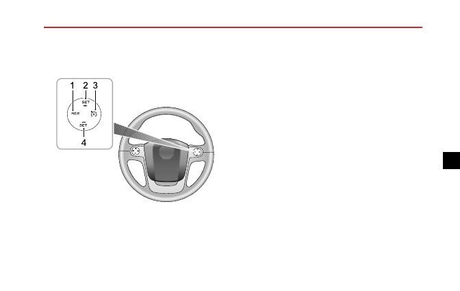
1
2 3
4
1 Reset switch
2 Increase set switch
3 Main switch
4 Decrease set switch
Cruise control enables the driver to maintain a constant
road speed without using the accelerator pedal.
This
is particularly useful for motorway cruising, or for any
journey where a constant speed can be maintained for a
lengthy period.
The following precautions must be observed when using
cruise control:
• DO NOT attempt to use cruise control when using
reverse gear.
• DO NOT use cruise control on winding or slippery road
surfaces, in the rain, or in traffic conditions where a
constant speed cannot easily be maintained.
• ALWAYS switch off the master switch when you no
longer intend to use cruise control.
Cruise Control System Operation
The cruise control system consists of four switches: the
main switch, reset switch and two speed increase/decrease
set switches. All switches are mounted at the right side of
the steering wheel.
1 When the current vehicle speed is above 25mph
(40KM/h), press down the master switch (3 in the
145
5