MINI Clubman (2018 year). Manual - part 7


  Index      MINI     MINI Clubman (2018 year) - manual in english


Search            copyright infringement  


Content      ..     5      6      7      8     ..


MINI Clubman (2018 year). Manual - part 7


-------------------------------------------------------------------------------------------------------------------------------------------------------------

CONTROLS
Displays
Displaying the cruising range
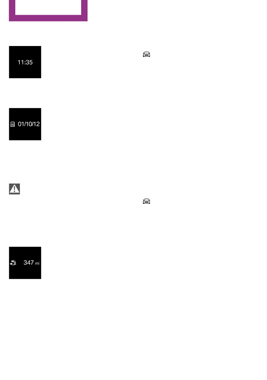
Time
Via the Central Information Display (CID):
The time is displayed in the in-
strument cluster.
1.
"My MINI"
The time can be set via the Cen-
2. "System settings"
tral Information Display (CID).
3. "Displays"
4. "Instrument panel"
5. "Range"
Date
The date is displayed in the in-
Current fuel consump-
strument cluster.
tion
The date can be set via the Cen-
tral Information Display (CID).
Concept
Displays the current fuel consumption. Check
whether you are currently driving in an efficient
Range
and environmentally-friendly manner.
Safety information
Displaying the current fuel
consumption
NOTE
Via the Central Information Display (CID):
With a driving range of less than
30 miles/50 km the engine may no longer have
1.
"My MINI"
sufficient fuel. Engine functions are not ensured
2. "System settings"
anymore. There is a risk of damage to property.
3. "Displays"
Refuel promptly.
4. "Instrument panel"
5. "Current consumption"
Display
With a low remaining range:
A Check Control message is
Service requirements
displayed briefly.
The remaining range is
Concept
shown on the Onboard Com-
The function displays the service requirements
puter.
and the corresponding maintenance scopes.
With a dynamic driving style, for instance
taking curves aggressively, the engine func-
General information
tion is not always ensured.
After the ignition is switched on the instrument
cluster briefly displays available driving distance
The Check Control message appears continu-
or time to the next scheduled maintenance.
ously below a range of approx. 30 miles/50 km.
A service advisor can read out the current serv-
ice requirements from your remote control.
112

-------------------------------------------------------------------------------------------------------------------------------------------------------------

Displays
CONTROLS
Display
6. Select the desired setting.
7. Confirm.
Detailed information on service
The entered date is stored.
requirements
More information on the type of service re-
quired may be displayed on the Control Dis-
Gear shift indicator
play.
Via the Central Information Display (CID):
Concept
1.
"My MINI"
The system recommends the most fuel efficient
2. "Vehicle status"
gear for the current driving situation.
3.
"Service required"
General information
Required maintenance procedures and le-
Depending on the vehicle's features and coun-
gally mandated inspections are displayed.
try-specific version, the gear shift indicator is
4. Select an entry to call up detailed informa-
active in the manual mode of the Steptronic
tion.
transmission and with manual transmission.
Suggestions to shift gear up or down are dis-
Symbols
played in the instrument cluster.
Symbols
Description
Manual transmission: displaying
No service is currently required.
Example
Description
Fuel efficient gear is set.
The deadline for scheduled
maintenance or a legally man-
dated inspection is approach-
Shift into fuel efficient gear.
ing.
The service deadline has al-
ready passed.
Steptronic transmission: displaying
Example
Description
Entering appointment dates
Enter the dates for the mandatory vehicle in-
Fuel efficient gear is set.
spections.
Make sure that the vehicle's date and time are
Shift into fuel efficient gear.
set correctly.
Via the Central Information Display (CID):
1.
"My MINI"
2. "Vehicle status"
3.
"Service required"
4. "Vehicle inspection"
5. "Date:"
113

-------------------------------------------------------------------------------------------------------------------------------------------------------------

CONTROLS
Displays
Overview
Speed Limit Info
Camera
Speed Limit Info
Concept
Speed Limit Info shows the current maximum
permitted speed in the instrument cluster.
General information
The camera at the base of the interior mirror
detects traffic signs at the edge of the road as
well as variable overhead sign posts. Traffic
signs with extra symbols for wet road condi-
The camera is installed near the interior mirror.
tions, etc., are also detected and compared
Keep the windshield in front of the interior mir-
with the vehicle's onboard data, such as from
ror clean and clear.
the rain sensor, and will be displayed depend-
ing on the situation.
Display
With the navigation system, the system takes
Speed Limit Info is displayed via the Onboard
into account the information stored in the navi-
Computer.
gation data and also displays speed limits
present on routes without signs.
Without a navigation system, the system is sub-
ject to limitations imposed by technology. Traf-
fic signs with speed limitations are detected
and displayed only. Speed limitations due to
entering or exiting towns, highway signs, etc.
are not displayed. Speed limits with extra text
characters are always displayed.
Safety information
Press button on the turn signal lever several
times, if needed.
WARNING
The system does not relieve from per-
Speed Limit Info is displayed on the Info Display
sonal responsibility to assess visibility and traffic
in the instrument cluster.
situation. There is a risk of an accident. Adjust
driving style to traffic conditions. Watch traffic
Speed Limit Info
closely and actively intervene where appropri-
The last speed limit detected.
ate.
Without a navigation system the
traffic signals are grayed out af-
ter curves or longer stretches of
roadway.
114

-------------------------------------------------------------------------------------------------------------------------------------------------------------

Displays
CONTROLS
With navigation system: Speed
Selection lists
Limit Info is not available.
General information
With the buttons on the steering wheel and the
display in the instrument cluster the following
Without navigation system: no
can be displayed or operated:
speed limit or cancellation is de-
Current audio source.
tected.
Redial phone feature.
Turn on voice activation system.
Speed Limit Info can also be displayed in the
Head-up Display.
Activating a list and adjusting the
setting
System limits
Button on the steering
Function
The system may not be fully functional and
wheel
may provide incorrect information in the fol-
Move selection up.
lowing situations:
In heavy fog, wet conditions, or snowfall.
Move selection down.
When signs are fully or partially concealed
by objects, stickers or paint.
Confirm the selection.
When driving very close to the vehicle in
front of you.
When driving toward bright lights or strong
Display
reflections.
When the windshield in front of the interior
mirror is fogged over, dirty or covered by a
sticker, etc.
In the event of incorrect detection by the
camera.
If the speed limits stored in the navigation
system are incorrect.
In areas not covered by the navigation sys-
tem.
When roads differ from the navigation, such
as due to changes in road routing.
Onboard Computer
When passing buses or trucks with a speed
Concept
sticker.
The Onboard Computer displays different vehi-
If the traffic signs are non-conforming.
cle data in the instrument cluster, such as aver-
During calibration of the camera immedi-
age values.
ately after vehicle delivery.
When signs that are valid for a parallel road
are detected.
115

-------------------------------------------------------------------------------------------------------------------------------------------------------------

CONTROLS
Displays
Calling up information on the Info
Speed Limit Info.
Display
Speed.
The unit of some information can be changed.
Setting units, refer to page 33.
Selecting information
You can select what information from the On-
board Computer is to be displayed on the Info
Display of the instrument cluster.
Via the Central Information Display (CID):
Press and hold button on signal lever.
1.
"My MINI"
Information is displayed in the Info Display of
2. "System settings"
the instrument cluster.
3. "Displays"
4. "Instrument panel"
Information at a glance
5. Select the desired information.
Info Display
Settings are stored for the profile currently
used.
Repeatedly pressing the button
on the turn signal lever calls up
the following information in the
Information in detail
Info Display:
Range
Range.
Displays the estimated cruising range available
GREEN Info.
with the remaining fuel.
When GREEN Mode is activated.
The range is calculated based on your driving
Average consumption, fuel.
style over the last 20 miles/30 km.
Current consumption, fuel.
GREEN info
Average speed.
The achieved range extension may be dis-
Date.
played as a bonus range.
Engine temperature display.
With equipment version with Head-up Dis-
Average fuel consumption
play and navigation:
This is calculated for the period while the en-
Distance to destination.
gine is running.
When destination guidance is activated in
The average fuel consumption is calculated for
the navigation system.
the distance traveled since the last reset by the
With equipment version with Head-up Dis-
Onboard Computer.
play and navigation:
Average speed
Time of arrival.
Periods in which the vehicle is parked with the
When destination guidance is activated in
engine manually stopped are not included in
the navigation system.
the calculation of the average speed.
116

-------------------------------------------------------------------------------------------------------------------------------------------------------------

Displays
CONTROLS
Resetting average values
The time must be correctly set.
Speed Limit Info
Speed Limit Info shows the current maximum
permitted speed in the instrument cluster.
Onboard Computer on the Control
Display
Concept
The Onboard Computer displays different vehi-
Press and hold button on turn signal lever.
cle data on the Control Display, such as average
values.
Engine temperature display
Displays the current engine temperature, based
General information
on a combination of coolant and engine oil
Two types of Onboard Computers are available
temperature. As soon as the optimum operat-
on the Control Display:
ing temperature has been attained, the indica-
"Onboard info": average values, such as the
tor is in the center position.
fuel consumption, are displayed. The values
If the engine oil or coolant, and thus the en-
can be reset individually.
gine, become too hot, a Check Control message
"Trip computer": the values deliver an over-
is displayed too.
view of a certain distance and can be reset
When the engine temperature is too
as often as necessary.
high, a red indicator light is displayed.
Calling up the Onboard Computer or trip
When the engine oil temperature is too
computer
high, a red indicator light is displayed.
Via the Central Information Display (CID):
Check the coolant level, refer to page 241.
1.
"My MINI"
2. "Driving information"
With equipment version with Head-up
3. "Onboard info" or "Trip computer"
Display and navigation: distance to
destination
Resetting the Onboard Computer
The distance remaining to the destination is
Via the Central Information Display (CID):
displayed if a destination is entered in the navi-
gation system before the trip is started.
1.
"My MINI"
The distance to the destination is adopted au-
2. "Driving information"
tomatically.
3. "Onboard info"
4. "Consumption" or "Speed"
With equipment version with Head-up
Display and navigation: time of arrival
5. "OK"
The estimated time of arrival is displayed if a
destination is entered in the navigation system
before the trip is started.
117

-------------------------------------------------------------------------------------------------------------------------------------------------------------

CONTROLS
Displays
Resetting the trip computer
Vehicle state
Via the Central Information Display (CID):
The following vehicle and surrounding area
data is automatically checked and evaluated in
1.
"My MINI"
succession:
2. "Driving information"
Range.
3. "Trip computer"
Engine temperature.
4. Move the Controller to the left, if needed.
External temperature.
"Reset": all values are reset.
SPORT program state.
"Automatic reset": all values are
Finally, a total evaluation of the vehicle state is
reset approx. 4 hours after the vehicle
displayed.
has come to a standstill.
5. If necessary, "OK"
Checking vehicle state
Via the Central Information Display (CID):
1.
"My MINI"
Driving Excitement
2. "Technology in action"
Concept
3. "Sport displays"
On the Control Display, sport instruments can
4.
"Vehicle and surroundings"
be displayed, and the vehicle state can be
Via the MINI Driving Modes switch:
checked before the use of the SPORT program.
1. Activate SPORT.
Sport instruments
2. "Sport displays"
3.
"Vehicle and surroundings"
General information
On the Control Display, values for power and
torque are displayed.
Speed warning
Displaying sport instruments
Concept
Via the Central Information Display (CID):
A speed limit can be set that when reached will
1.
"My MINI"
cause a warning to be issued.
2. "Technology in action"
General information
3. "Sport displays"
The warning is repeated if the vehicle speed
4.
"Sports instruments"
exceeds the set speed limit again, after it has
Via MINI Driving Modes switch:
dropped below it by 3 mph/5 km/h.
1. Activate SPORT.
Displaying, setting or changing the
2. "Sport displays"
speed warning
3.
"Sports instruments"
Via the Central Information Display (CID):
1.
"My MINI"
2. "Vehicle settings"
118

-------------------------------------------------------------------------------------------------------------------------------------------------------------

Displays
CONTROLS
3. "Speed warning"
Event displays
4. "Warning at:"
Functions that are only displayed temporarily,
for instance the volume or temperature set-
5. Turn the Controller until the desired speed
tings, can be set as event displays.
is displayed.
Several vehicle assistance functions can also be
6. Press the Controller.
displayed on the LED ring. This display corre-
sponds with the displays of the function in the
Activating/deactivating the speed
respective display.
warning
Via the Central Information Display (CID):
Example: tachometer
1.
"My MINI"
Like the tachometer in the instrument cluster,
2. "Vehicle settings"
the light animations of the tachometer's basic
display show the current RPMs and the respec-
3. "Speed warning"
tive RPM warning thresholds.
4. "Speed warning"
5. Press the Controller.
Display
Setting your current speed as the speed
warning
Via the Central Information Display (CID):
1.
"My MINI"
2. "Vehicle settings"
3. "Speed warning"
4. "Select current speed"
5. Press the Controller.
Arrow 1: current RPM.
Arrow 2: prewarning field.
Arrow 3: warning field.
LED ring on the central
instrument cluster
Switching on/off LED ring
Via the Central Information Display (CID):
Concept
1.
"My MINI"
The LED ring displays light animations to repre-
2. "System settings"
sent specific functions.
3. "Displays"
Basic displays
4. "Center Instrument"
Basic functions, for instance the tachometer,
5. "Center Instrument"
can be set to be displayed continually if so de-
sired.
Adjusting the LED ring
Via the Central Information Display (CID):
1.
"My MINI"
2. "System settings"
119

-------------------------------------------------------------------------------------------------------------------------------------------------------------

CONTROLS
Displays
3. "Displays"
Make sure that the area of movement of the
projection screen is clear during opening and
4. "Center Instrument"
closing.
5. "Basic display" or "Event display"
6. Select the desired setting.
NOTE
The Head-up Display consists of sensitive
Setting the brightness
components that can easily be scraped or dam-
The brightness can be adjusted when night
aged. There is a risk of damage to property. Do
lighting is active in the instrument cluster.
not place any objects on the Head-up Display,
attach to system components or plug into the
Via the Central Information Display (CID):
system. Do not move the moving parts man-
1.
"My MINI"
ually.
2. "System settings"
3. "Displays"
Overview
4. "Center Instrument"
5. "Brightness at night"
6. Turn the Controller until the desired bright-
ness is set.
7. Press the Controller.
The setting is stored for the driver profile cur-
rently used.
Head-up Display
Switching the Head-up Display on/off
When switching on, the projection lens of the
Concept
Head-up Display is extended. When switching
off, the projection lens of the Head-up Display
This system projects important information into
is retracted again.
the driver's field of vision, for instance the
speed.
Via the Central Information Display (CID):
The driver can get information without averting
1.
"My MINI"
his or her eyes from the road.
2. "System settings"
3. "Displays"
General information
4. "Head-Up Display"
Follow the instructions for cleaning the Head-
up Display. For additional information, see the
5. "Head-Up Display"
chapter on care.
Display
Safety information
Overview
WARNING
The following information is displayed on the
When extending and retracting the pro-
Head-up Display:
jection screen of the Head-up Display, body
parts can be jammed. There is a risk of injury.
Speed.
120

-------------------------------------------------------------------------------------------------------------------------------------------------------------

Displays
CONTROLS
Navigation system.
Adjusting the height
Check Control messages.
Via the Central Information Display (CID):
Selection list from the instrument cluster.
1.
"My MINI"
Driver assistance systems.
2. "System settings"
Some of this information is only displayed
3. "Displays"
briefly as needed.
4. "Head-Up Display"
5. "Height"
Selecting displays in the Head-up
Display
6. Turn the Controller until the desired height
Via the Central Information Display (CID):
is reached.
7. Press the Controller.
1.
"My MINI"
The setting is stored for the driver profile cur-
2. "System settings"
rently used.
3. "Displays"
The height of the Head-up Display can also be
4. "Head-Up Display"
stored using the memory function, refer to
5. "Displayed information"
page 76.
6. Select the desired displays in the Head-up
Display.
Setting the rotation
The screen of the Head-up Display can be ro-
Settings are stored for the driver profile cur-
tated around its own axis.
rently used.
Via the Central Information Display (CID):
Setting the brightness
1.
"My MINI"
The brightness is automatically adjusted to the
2. "System settings"
ambient brightness.
3. "Displays"
The basic setting can be adjusted manually.
4. "Head-Up Display"
Via the Central Information Display (CID):
5. "Rotation"
1.
"My MINI"
6. Turn the Controller until the desired setting
2. "System settings"
is selected.
3. "Displays"
7. Press the Controller.
4. "Head-Up Display"
The setting is stored for the driver profile cur-
5. "Brightness"
rently used.
6. Turn the Controller until the desired bright-
ness is set.
Display visibility
The visibility of the displays in the Head-up Dis-
7. Press the Controller.
play is influenced by the following factors:
When the low beams are switched on, the
Certain sitting positions.
brightness of the Head-up Display can be addi-
tionally influenced using the instrument light-
Objects on the cover of the Head-up Dis-
ing, refer to page 128.
play.
The setting is stored for the driver profile cur-
Sunglasses with certain polarization filters.
rently used.
Wet roads.
121

-------------------------------------------------------------------------------------------------------------------------------------------------------------

CONTROLS
Displays
Unfavorable light conditions.
Shift point indicator
John Cooper Works: sport displays in
Concept
the Head-up Display
Shift point indicator in the Head-up Display in-
dicates the optimum shifting point. Thus, with a
General information
sporty driving style, the best possible vehicle
The sport displays in the Head-up Display assist
acceleration is achieved.
with a sporty driving style.
Functional requirements
Switching on
Steptronic Sport transmission:
Via the Central Information Display (CID):
Manual mode M/S and, if necessary, Dy-
namic Traction Control DTC are activated.
1.
"My MINI"
Press the accelerator pedal all the way
2. "System settings"
down.
3. "Displays"
4. "Head-Up Display"
Display
5. "Displayed information"
Successive gray illuminated fields indicate the
6. "Sport displays"
upcoming shift moment.
With navigation system: if the sport displays are
Shift up immediately when the red fields light
switched on, no navigation content will be dis-
up.
played on the Head-up Display.
When the permitted maximum speed is
reached, all shift point indicators flash.
Display
When the maximum speed is exceeded, the
supply of fuel is interrupted in order to protect
the engine.
Vehicle status
General information
The status can be displayed and actions per-
formed for several systems.
1
Speed
2
Shift point indicator
Opening the vehicle status
3
Gear display
Via the Central Information Display (CID):
4
Current engine speed
1.
"My MINI"
5
Warning field, speed
2. "Vehicle status"
Information at a glance
"Flat Tire Monitor": Status of the Flat
Tire Monitor, refer to page 138.
122

-------------------------------------------------------------------------------------------------------------------------------------------------------------

Displays
CONTROLS
"Tire Pressure Monitor": Status of the
Tire Pressure Monitor, refer to page 133.
"Engine oil level": Electronic engine
oil level check, refer to page 237.
"Check Control": Check Control mes-
sages are stored in the background and can
be displayed on the Control Display. Dis-
playing stored Check Control messages, re-
fer to page 110.
"Service required": Displaying service
requirements, refer to page 112.
123

-------------------------------------------------------------------------------------------------------------------------------------------------------------

CONTROLS
Lights
Lights
Symbol
Function
Vehicle features and op-
tions
Lights off.
Daytime running lights.
This chapter describes all standard, country-
specific and optional features offered with the
Parking lights.
series. It also describes features that are not
necessarily available in your vehicle, e. g., due
to the selected options or country versions. This
Low beams.
also applies to safety-related functions and sys-
tems. When using these functions and systems,
the applicable laws and regulations must be
Instrument lighting.
observed.
Overview
Parking lights, low
Switches in the vehicle
beams and roadside
parking lights
General information
Position of switch:
,
,
If the driver's door is opened when the ignition
is switched off, the exterior lighting is automati-
cally switched off.
Parking lights
The light switch element is located next to the
steering wheel.
Position of switch:
The vehicle is illuminated on all sides.
Symbol
Function
Do not use the parking lights for extended peri-
Rear fog light.
ods; otherwise, the battery may become dis-
charged and it would then be impossible to
start the engine.
Front fog lights.
When parking, switch on the one-sided road-
side parking light, refer to page 125.
Automatic headlight control.
Low beams
Cornering light.
Position of switch:
The low beams light up when the ignition is
switched on.
124

-------------------------------------------------------------------------------------------------------------------------------------------------------------

Lights
CONTROLS
Canada: roadside parking light
3. "Lighting"
4. "Exterior lighting"
Concept
5. "Welcome lights"
The vehicle can be illuminated on one side.
The setting is stored for the driver profile cur-
rently used.
Switching on
Headlight courtesy delay feature
General information
The low beams stay lit for a short while if the
headlight flasher is switched on after the vehi-
cle's radio-ready state is switched off.
Setting the duration
Via the Central Information Display (CID):
With radio-ready state switched off, press the
lever either up or down past the resistance
1.
"My MINI"
point for approx. 2 seconds.
2. "Vehicle settings"
3. "Lighting"
Switching off
4. "Exterior lighting"
Briefly press the lever to the resistance point in
5. "Pathway lighting"
the opposite direction.
6. Set length of time.
The setting is stored for the driver profile cur-
rently used.
Welcome lights and
headlight courtesy de-
lay feature
Automatic headlight
control
Welcome lights
Concept
General information
The low beams are switched on and off auto-
Depending on the vehicle equipment and the
matically depending on the ambient bright-
ambient brightness, individual light functions
ness, for instance in tunnels, in twilight or if
may be switched on briefly when the vehicle is
there is precipitation.
unlocked.
General information
Activating/deactivating
A blue sky with the sun low on the horizon can
Position of switch:
,
cause the lights to be switched on.
Via the Central Information Display (CID):
Activating
1.
"My MINI"
Position of switch:
2. "Vehicle settings"
125

-------------------------------------------------------------------------------------------------------------------------------------------------------------

CONTROLS
Lights
The indicator light in the instrument cluster is il-
In tight curves, for instance on mountainous
luminated when the low beams are switched
roads or when turning, an additional, cornering
on.
light is switched on that lights up the inside of
the curve when the vehicle is moving below a
System limits
certain speed.
The automatic headlight control cannot serve
The cornering light is automatically switched on
as a substitute for your personal judgment of
depending on the steering angle or the use of
lighting conditions.
turn signals.
For example, the sensors are unable to detect
fog or hazy weather. To avoid safety risks under
these conditions, you should always switch on
Adaptive headlight
the lights manually.
range control
The adaptive headlight range control compen-
sates for acceleration and braking operations in
Daytime running lights
order not to blind the oncoming traffic and to
achieve optimum illumination of the roadway.
General information
Position of switch:
,
,
The daytime running lights light up when the
High-beam Assistant
ignition is switched on. After the ignition is
switched off, the parking lights light up in posi-
Concept
tion
The high-beam Assistant detects other traffic
participants early on and automatically
Activating/deactivating
switches the high beams on or off depending
In some countries, daytime running lights are
on the traffic situation.
mandatory, so it may not be possible to deacti-
vate the daytime running lights.
General information
Via the Central Information Display (CID):
The assistant ensures that the high beams are
1.
"My MINI"
switched on, whenever the traffic situation al-
lows. In the low speed range, the high beams
2. "Vehicle settings"
are not switched on by the system.
3. "Lighting"
The system responds to light from oncoming
4. "Exterior lighting"
traffic and traffic driving ahead of you, and to
5. Select the desired setting.
adequate illumination, for instance in towns
Settings are stored for the remote control cur-
and cities.
rently used.
The high beams can be switched on and off at
any time as usual.
Cornering light
General information
Position of switch:
126

-------------------------------------------------------------------------------------------------------------------------------------------------------------

Lights
CONTROLS
Activating/deactivating
In tight curves, on hilltops or in depressions,
in cross traffic or half-obscured oncoming
traffic on highways.
In poorly-lit towns and cities and in the
presence of highly reflective signs.
When the windshield in front of the interior
mirror is fogged over, dirty or covered with
stickers, etc.
Position of switch, depending on the vehicle
Fog lights
equipment:
,
Press and hold button on signal lever.
Front fog lights
The indicator light in the instrument
Concept
cluster is illuminated when the low
The front fog lights work alongside the low
beams are switched on.
beams to illuminate a wider area of the road-
way.
The headlights are automatically switched be-
tween low beams and high beams.
Functional requirement
The blue indicator light in the instru-
The low beams must be switched on before
ment cluster lights up when the system
switching on the front fog lights.
switches on the high beams.
Switching on/off
The high-beam Assistant is deactivated when
manually switching the high beams on and off,
Press button.
refer to page 92.
The green indicator light lights up if
To reactivate the high-beam Assistant, press
the front fog lights are switched on.
the button on the turn signal lever.
If the automatic headlight control, refer to
page 125, is activated, the low beams will
System limits
come on automatically when you switch on the
The high-beam Assistant cannot serve as a sub-
front fog lights.
stitute for the driver's personal judgment of
When the high beams or headlight flasher are
when to use the high beams. In situation that
activated, the front fog lights are not switched
require this, therefore switch off manually.
on.
The system is not fully functional in the follow-
ing situations, and driver intervention may be
Rear fog light
necessary:
In very unfavorable weather conditions,
Functional requirement
such as fog or heavy precipitation.
The low beams or the front fog lights must be
When detecting poorly-lit road users such
switched on before switching on the rear fog
as pedestrians, cyclists, horseback riders
light.
and wagons; when driving close to train or
ship traffic; and at animal crossings.
127

-------------------------------------------------------------------------------------------------------------------------------------------------------------

CONTROLS
Lights
Switching on/off
Overview
Press button.
The yellow indicator light lights up
when the rear fog light is switched on.
If the automatic headlight control, refer to
page 125, is activated, the low beams will
come on automatically when you switch on the
rear fog light.
1
Interior lights
Instrument lighting
2
Reading lights
3
Ambient light
Functional requirement
The parking lights or low beams must be
switched on to adjust the brightness.
Switching the interior lights on/off
Press button.
Settings
Adjust the brightness with the
To switch off permanently: press the button
thumbwheel.
and hold for approx. 3 seconds.
Switching the reading lights on and off
manually
Press button.
Interior lights
The reading lights are located in the front next
to the interior light.
General information
Depending on the equipment, the interior
Ambient light
lights, footwell lights, entry lights, and courtesy
lights are controlled automatically.
General information
Thumbwheel for the instrument lighting con-
Depending on the equipment version, lighting
trols brightness of some of these features.
can be adjusted for some lights in the car's in-
terior.
Activating/deactivating
Via the Central Information Display (CID):
1.
"My MINI"
2. "Vehicle settings"
3. "Lighting"
4. "Interior lighting"
128


Content      ..     5      6      7      8     ..