Tractors X60 Series. Manual - part 59
 

  Index      Tractors     Tractors X60 Series - service repair manual 2012 year


Search            


Content   ..  57  58  59  60   ..


Tractors X60 Series. Manual - part 59


Electrical system

235

8

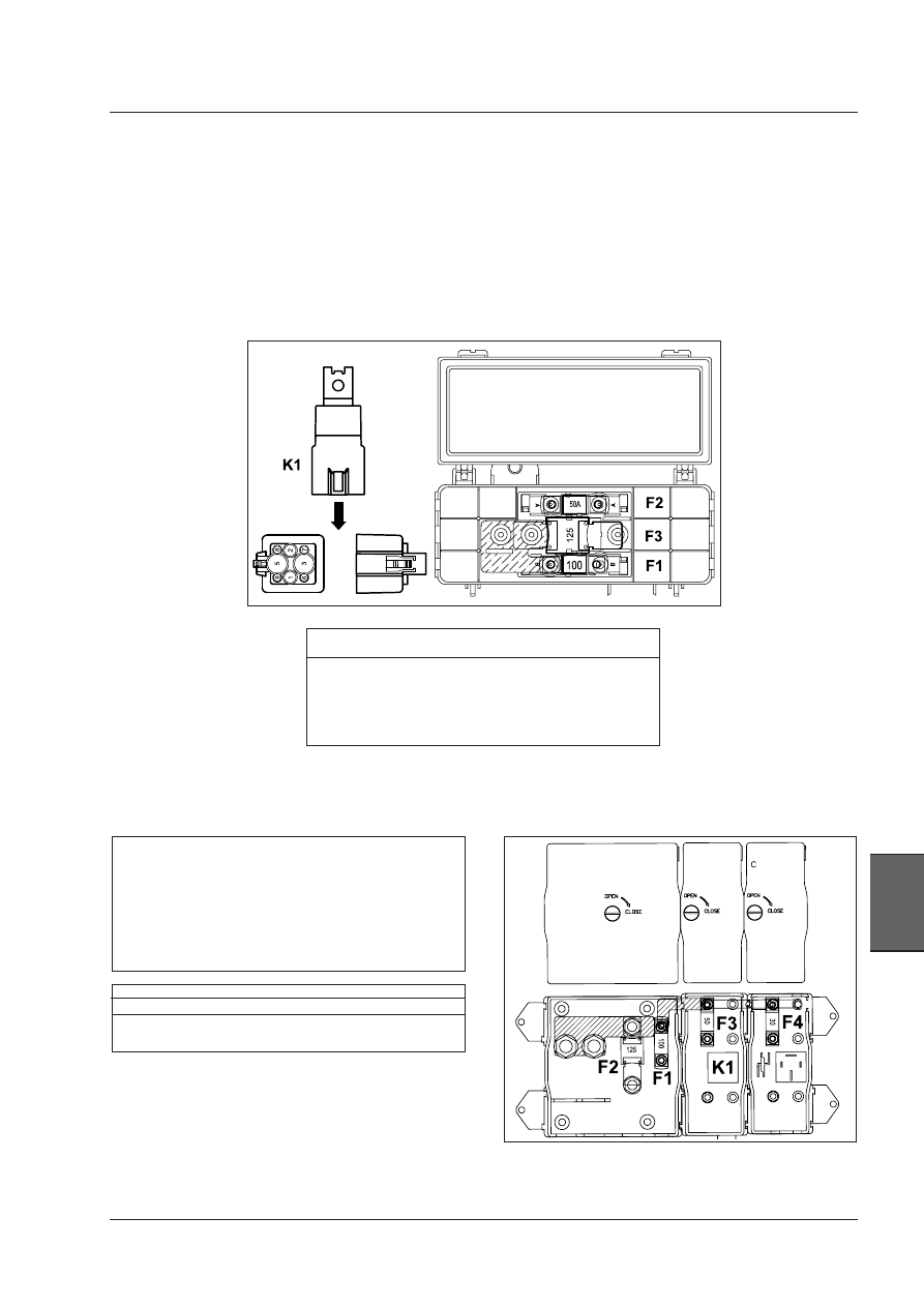
Fuse

Function

Amps

F1

Alternator protection

100

F2

Power to cab protection

125

F3

Grid heater power supply (Glow plugs)  50

F4

Engine controller protection

30


Relay 

Function

 K1

Glow plug relay

Relay 50A

Fuse

Function

Amps

F1

Alternator protection

100A

F2

Power to cab

125A

F3

Power to glow plugs (grid heater)

50A

K1

Glow plug relay - 50A relay

NOTE: Before replacing a blown fuse with a new, 
equivalent one, the cause that led to the fault should be 
ascertained and removed.

WARNING: To carry out this operation, engage the first 
gear, turn off the engine, engage the parking brake 
and remove the ignition key.

WARNING: Always use specific personal safety devices 
for each operation. 

Battery fuses and relays - Mechanical engine

Battery fuses and relays - Electronic engine

Electrical system

236

Replacement of lamps

Turn and remove from its seat the connector of the lamp
holder.
Replace the lamp.

Headlights

As you can use your tractor on public roads, the lighting
must comply with the applicable traffic and road regu-
lations.  Periodically  check  headlight  alignment  in  the
following way:

Checking headlight alignment

-  Halt the tractor on level ground facing a shaded wall

(preferably white). The tractor must be unloaded and
the tyres correctly inflated. Mark two crosses on the
wall in front of the tractor headlight centres.

-  Reverse the tractor 5 meters (16.4 ft) away from the

wall.

-  Switch on the main beam.
 The centre of each beam must be vertically aligned with

the crosses on the wall.

 A maximum outward divergence of 130 mm (5 in) is

acceptable.

- Switch on the dipped beams.
 The line separating the lighted area from the dark area

must  fall  below  the  crosses  and  must  be  separated
from their centres by at least 1/20th of the height of
the crosses from the ground.

- Adjust the headlight alignment screws to correct ali-

gnment as necessary.

Checking headlight alignment

WARNING: Always use specific personal safety devices 
for each operation. 

Electrical system

237

8

WARNING: Always use specific personal safety devices 
for each operation. 

7-pin power socket for trailer

A 7-pole power socket is installed on the rear of the trac-
tor (1). This socket is used to connect the light circuits
of the trailer.

Connections  and  correspondences  for  7-pole  power
socket according to ISO-SAE standards.

1. Lh turn indicator;
2. Not used (Fog lights - if equipped);
3. Earth;
4. Rh turn indicator;
5. Rh rear marker light;
6. Brake lights;
7. Lh rear marker light.

North American Tractors

Connections

Rest Of World Tractors

Connections

Pin number 4 and 7 are controlled through the key switch.
These circuits are protected by a 30 A fuse. See the Fuse
chapter in this manual.

TERMINAL N. CIRCUIT (CABLE COLOUR)
1 .....................................................................GROUND (WHITE)

2 ............................................................. FIELD LIGHTS (BLACK)

3 ...........................................LEFT TURN INDICATOR (YELLOW)

4 .........................................................AUXILIARY POWER (RED)

5 ........................................... RIGHT TURN INDICATOR (GREEN)

6 ..............................................................TAIL LAMPS (BROWN)

7 .......................................................AUXILIARY POWER (BLUE)

Electrical system

238

Three-pin electrical sockets, 12V

On the right side of the dashboard

On the right-hand console behind the seat.

Two auxiliary electrical power sockets are provided inside
the  operators  compartment  for  connecting  monitors,
implement  controllers,  C.B.  radios,  and  other  12  volt
equipment.

NOTE:  The  correct  3  pin  plug  to  fit  the  sockets  can  be 
obtained from your dealer.

FRONT VIEW

A. NORTH AMERICA B. OTHER COUNTRIES

Connections
1- Positive, key operated - Max. load 5A
2- Positive direct to battery - Max. load 25A
3 - Negative - Ground

WARNING: Always use specific personal safety devices 
for each operation. 


Content   ..  57  58  59  60   ..