Tractors X60 Series. Manual - part 58
 

  Index      Tractors     Tractors X60 Series - service repair manual 2012 year


Search            


Content   ..  56  57  58  59   ..


Tractors X60 Series. Manual - part 58


Electrical system

231

8

Connection of a booster battery to 

the positive battery terminal on the 
tractor

IMPORTANT: When connecting a booster battery to the 
tractor positive terminal, make sure the batteries are the 
same voltage (i.e. 12 Volt) and the electrolyte is at the cor-
rect level. DO NOT connect auxiliary battery cables across 
the terminals of the starter. Always start the engine from 
the operator's seat.

WARNING: Always connect the ground cable 
last  and  disconnect  the  ground  cable  first 
so you do not cause a spark at the battery. 
A spark can cause a battery explosion and 
cause injury.

Procedure

OPERATION 1

Position the machine with the booster battery next to the
tractor so that the booster cables can be connected eas-
ily. MAKE SURE THE MACHINES ARE NOT TOUCHING.

OPERATION 2
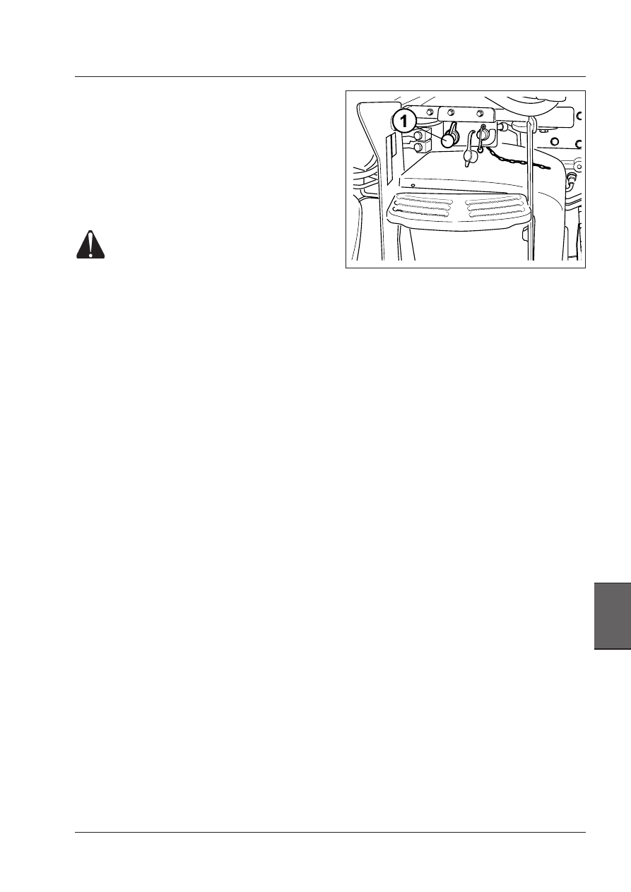
Remove the red cap from the positive terminal (1).

Connect  the  booster  battery  positive  (+)  to  the 
tractor positive terminal (+) and the negative (-) 
to a good ground on the tractor frame, not to the 
tractor battery terminal.

OPERATION 3
Start the engine of the machine with the booster battery
and run the engine for approximately 2 minutes.

OPERATION 4
Start  the  tractor  engine.  See  correct  procedure  in  this
manual.

OPERATION 5
When the tractor engine has started, disconnect the nega-
tive booster cable from the tractor frame and the booster
battery  negative  first,  then  the  positive  cable  from  the
tractor terminal and the booster battery.

Install the red cap on the positive terminal after the start-
ing operation has been completed. (The position of the
terminal depends on tractor model)

WARNING: Always use specific personal safety devices 
for each operation. 

Electrical system

232

Electrical system - Warnings

It is absolutely forbidden to make changes or connections
to  the  data  interconnecting  lines  between  control
units  (CAN-BUS  lines).  They  are  to  be  considered  as
INVIOLABLE. All diagnostic and maintenance operations
may only be carried out by authorized technicians, with
specific appliances approved by Landini.
Use only fuses with the rated capacity for their specific
function. Do not ever use fuses with higher rated capacity.
Replace  a  blown  fuse  only  after  correcting  the  relative
malfunction  and  turn  off  any  keys  and  users  before
replacing.
Please  keep  in  mind  that  electrical  systems  made  by
unqualified persons might severely damage the systems
on board the tractor (control units, harnesses, sensors
etc.), and jeopardize the riding safety and good operation
of  the  tractor.  Such  damages  ARE  NOT  COVERED  BY
OUR CONTRACT WARRANTY.
Never  disconnect  control  unit  and  sensor  connectors
while  the  engine  is  running  and  the  control  units  are
powered.
Negative  conductors  connected  to  a  grounding  point
of  the  system  must  be  as  short  as  possible  and  star
connected with each other.
As a principle, the grounding connections of the tractor
may not be changed.
If  the  creation  of  further  grounding  points  is  required,
the holes already provided on the frame must be used,
taking care of the following
- remove lacquer from the frame
- use a suitable highly conductive lacquer between frame
and cable terminal
-  connect  the  ground  within  5  minutes  from  lacquer
application

THE  POINTS  PROVIDED  FOR  ENGINE  CONNECTION
TO  GROUND  MUST  BE  ABSOLUTELY  AVOIDED  FOR
GROUND CONNECTIONS

1 - Ground connection; A. Efficient grounding point; B.
Not efficient grounding point;
2  -  Cable  fastening:  A.  Screw;  B.  Cable  terminal;  C.
Washer; D. Nut
3 - Correctly grounded cable.


B


A

Starter motor

The  starter  motor  should  be  thoroughly  cleaned  after
periods of 1000 hours or at least once a year. Parti-

cularly check the condition of the brushes and collector.

Alternator

The alternator keeps the battery fully charged.
The  alternator  is  a  brushless  model  and  requires  no
special maintenance. However, the following precautions
must be observed.

1 - When fitting a battery, make sure that the positive

and negative terminals are connected to the same
leads as the alternator. If the battery terminals are
inverted, you will short circuit the battery through
the alternator diodes.

2 - When connecting the battery to a charger, make

sure that the positive (+) lead of the charger is
connected to the positive of the battery and the
negative (-) to the negative. Incorrect connection
will damage the diodes and the other circuit
components.

3 - Never run the alternator unless it is properly

connected.

  If the battery is not connected, high voltages can

build up inside the alternator that can be extremely
dangerous if the output terminal is touched.

  Make sure that all connections are firm and tight

before carrying out any inspections or tests on the
electrical system.

4 - Never short circuit or earth any of the alternator

terminals. This could damage the electrical system.

5 - Never invert the alternator connections. The battery

and alternator earths must be of the same sign or
the alternator diodes will be damaged.

6 - Always disconnect both alternator terminals before

undertaking any electric arc welding on the tractor.

WARNING: Always use specific personal safety devices 
for each operation. 

Electrical system

233

8

FUSE LOCATION AND IDENTIFICATION

The fuses give protection to the electrical circuits of
the tractor and cab.

To service the fuses remove the left hand side panel
from the front console. To replace a fuse, pull the
fuse out of the clips and push a new fuse in.

Fuses on dashboard - View from the front

NOTE: Before replacing a blown fuse with a 
new, equivalent one, the cause that led to the fault 
should be ascertained and removed.

WARNING: To carry out this operation, engage 
the  first  gear,  turn  off  the  engine,  engage  the 
parking brake and remove the ignition key.

WARNING:  Always  use  specific  personal  safety 
devices for each operation. 

 Fuse  

Function 

Amps

FC

Electric fan supply AC cab

40

FA1

Starter motor

25

FA2

Ignition key feed line

5

FA3

Front external field lights on roof, feed line

10

FA4

Front internal roof field light and handgrip switch

10

FA5

Rear external field lights on roof and NAO rear 7-pin socket, feed line

10

FA6

Feed line for rear internal roof field lights-mudguards

10

FA7

Differential lock and brake lights feed line

15

FA8

Turn indicators

10

FA9

Dipped beams, driving beams, flashing beams, horn feed line,

NAO card feed line

10

FA10

Feed line to NAO accessories (7-pin socket)

5

FA11

Pneumatic seat feed line

10

FA12

Emergency switch feed line

15

FA13

General side lights

7.5

FA14

Direct power supply from battery to 7-pin socket

20

FA15

Rh side lights + license plate

5

FA16

Lh side lights + license plate, night lighting of controls and console

5

FA17

Rotating beacon on cab and trailers, feed line

7.5

FA18

Auxiliary socket, dashboard and cab rh lining

10

FA19

Front loader feed line (if installed)

7.5

FA20

Free

-

FB1

Auxiliary socket, dashboard

20

FB2

Auxiliary socket, cab rh lining

20

FB3

Cigarette lighter feed line

10

FB4

Radio, key-operated feed line

7.5

FB5

Direct feed line battery to radio and roof light on cab entry

5

FB6

Driving beams feed line

15

FB7

Dipped beams feed line

10

FB8

Free

-  

FB9

Rear windscreen wiper and washer

7.5

FB10

Front window wiper and washer

10

FB11

DIA1 diagnostic socket and instrument feed line

3

FB12

Instrument, buzzer and parking brake coil feed line

5

FB13

Feed line to mechanical and electronic engine

7.5

FB14

Transmission controller

7.5

FB15

Four-wheel drive

5

FB16

Front power take-off (on request)

5

FB17

Trailer brake and air brakes control (if equipped)

5

FB18

Electronic hitch controller

5

FB19

Air conditioner compressor

7.5

FB20

Free

-

Electrical system

234

Relays on dashboard - View from the front

NOTE: Before replacing a blown fuse with a new, 
equivalent one, the cause that led to the fault should be 
ascertained and removed.

WARNING: To carry out this operation, engage the first 
gear, turn off the engine, engage the parking brake 
and remove the ignition key.

WARNING: Always use specific personal safety devices 
for each operation. 

  Relay 

Function 

 KA1

Starter motor relay

Relay 30A

 KA2

Rear field lights on roof, rear fenders, NAO 7-pin socket

Relay 30A

 KA3

Differential lock and brake lights, turn indicator lights, headlights,


NAO 7-pin socket and air seat

Relay 30A

 KA4

Relay for driving beams, dipped beams, rear and front window wiper, rear and front window washer

Relay 30A

 KA5

Field lights corner light, on front of roof and front safety handles

Relay 30A

 KA5

Instrument, feed line to mechanical and electronic engine, transmission controller,


four-wheel drive, front PTO (if equipped), trailer brakes (if equipped)


and electronic hitch controller

Relay 30A

 KA6

Brake lights control relay

Relay 30A

 KB1

Air conditioning safety relay, Deluxe roof and Low Profile roof

Relay 30A

 KB2

Differential lock self-retaining relay

Relay 30A

 KB3

Driving beam relay

Relay 30A

 KB4

Dipped beam relay

R e l a y

30A

 KB5

Rear PTO safety

Relay 30A

 KB6

Parking brake microswitch relay for hydraulic and air trailer brake

Relay 30A

 KC1

Auxiliary socket on dashboard, auxiliary socket on rh lining and cigarette lighter relay

Relay 70A

 KC2

Air conditioning solenoid relay

Relay 40A

 K2

Front loader control pre-engineering relay (if provided)

Relay 30A

 K3

Front roof field light and handgrip relay

Relay 30A


Content   ..  56  57  58  59   ..