Snowmobile Arctic Cat 2-Stroke (2007 year). Manual - part 92


  Index      Snowmobiles / ATV     Snowmobile Arctic Cat 2-Stroke - service manual 2007 year


Search            


Content   ..  90  91  92  93   ..


Snowmobile Arctic Cat 2-Stroke (2007 year). Manual - part 92


7-54

Gas Tank/

Seat Assembly

(F-Series)

REMOVING

1. Remove the hood and open the right-side and

left-side access panels.

2. Remove the two torx-head cap screws (A)

securing the console to the chassis; then lift up

the rearward end of the console and disconnect

the console harness plug-in. Remove the con-

sole.

0741-965

3. Remove the two torx-head cap screws (B) secur-

ing the handlebar close-off panel; then remove

the three torx-head cap screws (C) securing the

rear side panels (spars) to the seat support tubes. 

4. Remove the two screws (D) securing the knee

pads to the gas tank; then remove the remaining

body screws securing the knee pads to the steer-

ing support.

5. Adjust the seat to the lowest position; then while

lifting on the top forward part of the seat,

remove the machine screw (E) from the right

side of the seat support assembly. Remove the

seat.

6. Remove the four cap screws (F) securing the

support tubes to support plate.

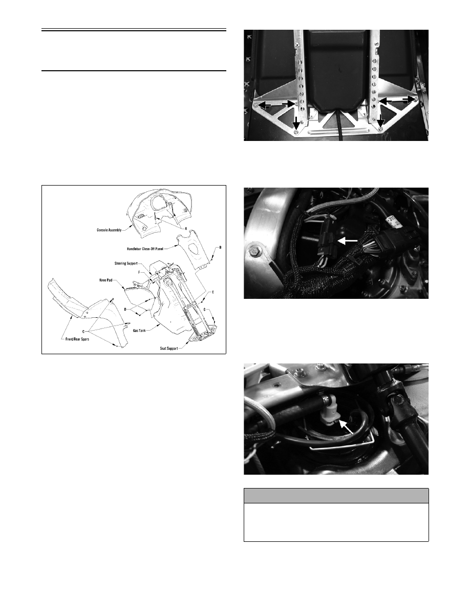
7. Remove the six torx-head screws (G) securing

the seat support assembly to the tunnel; then

slide the support back out of the way.

ZJ010A

8. Disconnect the fuel pump four-wire connector;

then slide the gas tank rearward enough to gain

access to the gasline hose connector.

FS261A

9. Compress the clip on the gasline hose connector

and remove the hose from the gas tank; then dis-

connect the gas tank vent hose and close off the

vent hose outlet of the gas tank and remove the

gas tank.

FS262A

! CAUTION

The gasline supply hose may be under pressure.
Place an absorbent towel around the connection to
absorb gasoline; then remove the hose slowly to
release the pressure.

7-55

7

INSTALLING

1. Install the gasline hose onto the tank and press

down on the connector until it snaps into place;

then install the vent hose to the outlet and secure

with the hose clamp.

FS262B

2. Install the gas tank to its proper position; then

secure the tank with the seat support assembly

and install the four cap screws (F) securing the

seat support tubes to the support plate. Tighten

securely.

0741-965

„ NOTE: Prior to installing the cap screws, it may
be necessary to align the U-nut clips with a punch.

3. Install the six torx-head cap screws (G) securing

the seat support assembly to the tunnel.

4. Connect the fuel pump four-wire connector.

FS261A

5. Install the screws (D) and the body screws

securing the knee pads to the gas tank and the

steering support; then secure the rear side panels

(spars) with the three torx-head cap screws (C)

for each side.

6. Install the handlebar close-off panel; then secure

the panel with the two torx-head cap screws (B).

Position the console assembly on the headlight

support bracket; then connect the main hood

harness.

7. Install the console to the steering support with

the two torx-head cap screws (A). Tighten

securely.

8. Install the hood; then close the side access panels.

9. Install the seat; then install the machine screw

(E) (threads coated with blue Loctite #243) to

the right side of the seat support.

Seat Cushion

„NOTE: Some components may vary from model
to model. The technician should use discretion
and sound judgment. 

REMOVING

1.  Remove the gas tank/seat assembly (see the appro-

priate Gas Tank/Seat Assembly in this section).

2. Remove the two screws securing the taillight

cover; then remove the cover. 

3. Remove the two screws securing the front of the

seat cushion to the seat base. 

4.  Using a sharp tool, pry out all staples securing the

seat cover to the plastic seat base.

! CAUTION

Prior to continuing the installing procedure, make
sure the gasline hose is properly and securely
“snapped” onto the gas tank.

! CAUTION

It is critical that machine screw (E) is not installed
tight against the seat support. The screw must be
loose enough to be effective as a seat “stop.”

7-56

5.  From beneath the seat foam, remove the seat wire

from the two elastic loops; then remove the cover

from the seat base and seat foam.

INSTALLING

„NOTE: If the seat cover was removed, position
the cover over the seat foam and plastic seat base.
Check to make sure it is positioned straight; then
fold the rear edge of the cushion down and around
the base. Using a staple gun and 6 mm (1/4 in.) sta-
ples, staple the rear flap of the cushion to the base
in the same areas as the original staples were
located. Position staples 2.5 cm (1 in.) apart. Fold
the sides of the cushion down around the bottom
edge of the base. Position the staples in the same
areas as the original staples were located.

1. Position the cover over the seat foam and seat

base; then pull the two elastic loops through the

slots in the seat foam and secure with the seat

wire. Check to make sure it is positioned straight. 

2.  Fold the rear edge of the cushion down and around

the plastic base. Using a staple gun and 6 mm (1/4

in.) staples, staple the rear flap of the cushion to

the plastic base in the same areas as the original

staples were located. Position staples 2.5 cm (1

in.) apart. 

3.  Fold the sides of the cushion down around the bot-

tom edge of the plastic seat base. Position the sta-

ples in the same area as the original staples were

located. 

„NOTE: Note the cushion fit. If any wrinkles are
noted, remove by pulling the cushion material in
the appropriate direction before securing with sta-
ples.

4. Fold the front cushion material back and onto the

plastic seat base. Check for wrinkles and secure

with staples and two screws.

5. Install the taillight housing and secure with the

screws.

6.  Install the gas tank/seat assembly (see appropriate

Gas Tank/Seat Assembly in this section).

Taillight/Brakelight

Assembly

REMOVING (Bearcat/Panther/Z)

1. Remove the four screws securing the taillight lens

to the housing. Account for a gasket.

2. Remove the four machine screws securing the

backing plate to the taillight housing.

3. Remove the two screws, lock washers, and wash-

ers securing the seat base to the tunnel. Lift the

seat from the tunnel. Disconnect the taillight wir-

ing harness.

4. Remove the two lock nuts and washers securing

the taillight housing to the rear of the seat base.

Pull the housing free of the base.

INSTALLING (Bearcat/Panther/Z)

728-384B

1. Connect the wiring harness and place the seat into

position. Secure with two screws, lock nuts, and

washers.

2. Place the taillight housing into position and secure

to the seat base with two lock nuts and washers.

Tighten securely.

3. Install the lens. Secure lens with four screws.

4. Secure the backing plate to the taillight housing

with the existing machine screws.

REMOVING (Crossfire/F-Series/
M-Series)

1. On the F-Series, from inside the rear storage com-

partment, remove the self-tapping screws and

washers securing the taillight/brakelight housing.

! CAUTION

On Bearcat/Panther/Z models, beneath the seat base
is a dotted guideline to follow when stapling the seat
cover. Do not staple inside this guideline or perfora-
tion of the gas tank may occur.

KEY

1. Taillight w/Socket Assy

2. Bulb

3. Gasket

4. Lens

5. Retaining Screw

7-57

7

741-680A

2. On the Crossfire/M-Series, remove the machine

screw securing the taillight/brakelight housing to

the rear bumper; then remove the two self-tapping

screws and washers securing the taillight/brake-

light to the housing.

0742-338

3. Disconnect the harness connector and remove

housing.

INSTALLING (Crossfire/F-Series/

M-Series)

1. Connect the harness connector.

2. On the Crossfire/M-Series, secure the taillight/

brakelight to the housing with the two self-tapping

screws and washers; then secure the housing to the

rear bumper with the machine screw.

3. On the F-Series, place the housing into position;

then from inside the rear storage compartment,

secure with the self-tapping screws and washers.

Windshield

(Bearcat/Crossfire/M-Series/

Panther/Z)

REMOVING

740-254A

739-527A

1. Remove the O-rings securing windshield to the

hood.

2. Remove the caps covering the screws; then

remove the screws w/snaps.

3. Remove the windshield.

INSTALLING

1. Place the windshield into position and install the

O-rings.

2. Secure the windshield to the hood with screws w/

snaps. Install the caps.

KEY

1. Windshield

2. O-Ring

3. Rivet

Crossfire/M-Series

KEY

1. Windshield

2. Machine Screw

3. Snap and Cap

4. Expansion Nut

5. O-Ring

6. Mirror

Bearcat/
Panther/Z


Content   ..  90  91  92  93   ..