Snowmobile Arctic Cat 2-Stroke (2007 year). Manual - part 91


  Index      Snowmobiles / ATV     Snowmobile Arctic Cat 2-Stroke - service manual 2007 year


Search            


Content   ..  89  90  91  92   ..


Snowmobile Arctic Cat 2-Stroke (2007 year). Manual - part 91


7-50

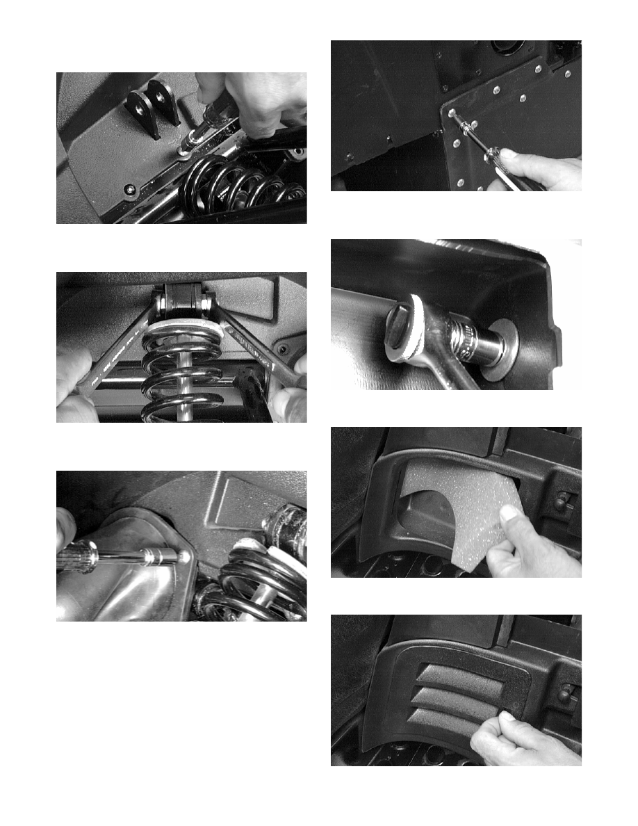
4. Install the belly pan torx-head screws underneath

the shock mount.

AL179D

5. Install the shock absorber. Tighten to specifica-

tions.

AL178D

6. Install the right-side steering tie rod boot. Secure

with the screws.

AL190D

7. Install the right-side belly pan torx-head screws to

the center belly pan and tunnel; then return the

snowmobile to an upright position.

AL188D

8. Install the right-side cap screws securing the

bumper to the air-intake silencer plenum.

AL186D

9. Insert the right-side louver foam.

AL185D

10. Install the right-side louver.

AL184D

7-51

7

11. Install the right-side front belly pan cap screw,

washer, and lock nut.

AL183D

Belly Pan

(Crossfire/M-Series)

REMOVING

1. Remove the access panels and the hairpin clips

from the hood pins; then remove the pins securing

the hood to the front bumper.

FC219

FC220

2. Disconnect the ignition harness; then remove the

torx-head screws securing the air silencer to the

front bumper.

FC217

3. Remove the remaining torx-head screws securing

the front bumper. Account for the center belly pan

screen.

FC221

FC222

4. Remove the torx-head screws securing the center

belly pan to the frame. Note the location of differ-

ent-length screws for installing purposes.

! CAUTION

To avoid damage to the hood, carefully close it and
rest it on the handlebar.

7-52

FC224

5.  Remove the center belly pan.

FC225

„NOTE: If removing the right-side belly pan only,
the resonator must be removed. If removing the
left-side belly pan only, the clutch guard must be
removed. 

6. Remove the torx-head screws securing each side

belly pan to the frame.

7.  Using a 3/16 in. drill bit, drill out the rivets secur-

ing each side belly pan to the frame; then remove

the belly pans.

INSPECTING

1.  Inspect for gouges, cuts, and tears.

2.  Inspect all belly pan threaded bosses that they are

in good shape. 

INSTALLING

„NOTE: Steps 1-2 should be used for each side
belly pan.

1. Place the side belly pan into position on the frame;

then secure with the torx-head screws.

2. Using an appropriate rivet gun, secure the side

belly pan with six rivets.

3. Place the rear belly pan into position; then secure

with the torx-head screws.

FC224

4. Place the front bumper into position; then secure

with the eight torx-head screws. Place the center

belly pan screen into position.

FC221

FC222

5. Place the air silencer into position on the front

bumper; then secure with the torx-head screws.

Connect the ignition harness.

FC217

7-53

7

6. Place the hood into position on the front bumper;

then install the two hood pins and hairpin clips.

FC219

„NOTE: If applicable, install the resonator and/or
the clutch guard.

Gas Tank/

Seat Assembly

(Bearcat/Panther/Z)

„NOTE: Some components may vary from model
to model. The technician should use discretion
and sound judgment.

REMOVING

„NOTE: If so equipped, turn the gas tank shut-off
valve to the CLOSED position. 

1. Remove the console (see the appropriate Console

in this section).

2. Remove the two cap screws, washers, and lock

nuts (located in the rear compartment) securing the

seat to the tunnel.

3.  Remove the vent hose from the gas tank.

4. Raise the rear of the seat high enough to discon-

nect the taillight wiring harness.

5. Slide the gas tank/seat assembly back far enough

to access the fuel hose; then disconnect the fuel

hose. 

6.  Remove the gas tank/seat assembly.

INSTALLING

1. Place the seat in position on the tunnel; then con-

nect the fuel hose. 

2.  Connect the vent hose to the gas tank.

3. Raise the rear of the seat high enough to connect

the taillight wiring harness making sure the har-

ness is positioned into the groove of the seat base.

4.  Secure the seat to the tunnel with two cap screws,

washers, and lock nuts.

5.  Install the console (see the appropriate Console in

this section).

Gas Tank/

Seat Assembly

(Crossfire/M-Series)

REMOVING

1. Trip the seat latches inside the storage compart-

ment and remove the seat.

2. Remove the console (see the appropriate Console

in this section).

3.  Drain the gasoline from the gas tank.

4. Remove the two lock nuts securing the steering

post mounting blocks to the gas tank; then remove

the two lock nuts securing the gas tank to the chas-

sis. Disconnect the fuel hose and the fuel pump

two-wire connector; then remove the gas tank.

CM003A

INSTALLING

1. Install the gas tank onto the steering post mounting

blocks and the steering support; then secure the

gas tank to the chassis and to the steering support

with the four lock nuts. Connect the fuel hose and

the fuel pump two-wire connector.

2.  Install the console (see the appropriate Console in

this section).

3. Place the seat into position and secure with the

latches inside the storage compartment.


Content   ..  89  90  91  92   ..