Snowmobile Arctic Cat (2002 year). Manual - part 176


  Index      Snowmobiles / ATV     Snowmobile Arctic Cat - service manual 2002 year


Search            


Content   ..  174  175  176  177   ..


Snowmobile Arctic Cat (2002 year). Manual - part 176


9-182

Servicing Rebuildable 

Shocks & Remote 

Reservoir w/Clicker

REMOVING AND DISASSEMBLING

1. Remove the shock absorber from the snowmobile.

Remove the mounting bushings and bearings from

the shock.

2. Wash the shock body and reservoir in parts-clean-

ing solvent; then dry with compressed air to

remove sand and dirt.

3. Remove the screw from the bladder housing on

bottom of shock reservoir; then discharge all pres-

sure from the shock reservoir using Shock Infla-

tion Needle (p/n 0644-158). Open valve in filler

handle until all pressure is released.

AG851

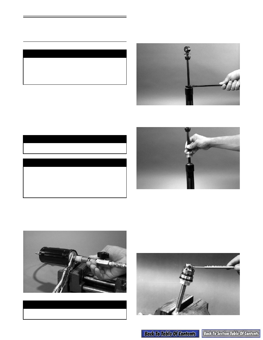
4. Clamp the shock body eyelet in a vise; then using

a 1-in. wrench, unscrew the shaft bearing cover.

„

NOTE: If the shock body turns in lower end cap,

use shock blocks to hold the shock.

AG852

5. With the bearing cover loosened, lift the shaft

assembly from the shock body.

AG853

6. Remove the piston ring from the piston.

7. Loosen (BUT DO NOT REMOVE) the self-lock-

ing nut from the bottom of the shock shaft; then

clean the piston area with clean parts cleaner to

remove any dirt or foreign material from between

the valves. Dry the piston and valves completely

using compressed air. Tighten self-locking nut to

2.1-2.8 kg-m (15-20 ft-lb). Do not over-tighten! If

excess torque is applied, the piston and valves will

be damaged.

AG280

! WARNING

Before servicing a gas shock absorber, first dis-
charge all pressure from the reservoir. Remove the
screw from the top of the reservoir and insert the
Shock Inflation Needle (p/n 0644-158). Open valve
until all pressure is released. Failure to do this may
cause personal injury.

! WARNING

When using compressed air to dry components,
always wear safety glasses.

! WARNING

When working with Shock Inflation Needle (p/n
0644-158), use extreme care. Misuse of this tool
may cause personal injury or death. Avoid punctur-
ing skin with needle. Pressurized air injected
through the skin may be fatal. Do not release safety
mechanism unless red nose piece is inserted in
shock absorber air valve.

! WARNING

Failure to remove pressure from shock reservoir
may result in personal injury.

9-183

9

„

NOTE: Do not remove the self-locking nut from

the bottom of the shock rod unless piston or pis-
ton valve changes are needed as it is very impor-
tant the valving on either side of the piston stay in
the proper position.

8. Install the piston ring on the piston.

9. Push down on the reservoir end cap compressing it

2.5 cm (1 in.) into the reservoir; then remove the

reservoir cap retainer ring. Use care not to scratch

the inside of the reservoir.

AG854

„

NOTE: With the retainer ring removed, wipe the

ring area clean to remove any foreign materials.

10. Remove the reservoir end cap by grasping the

bladder housing with a pliers and pulling the cap

slowly out of the reservoir body.

AG855

11. Remove the Allen-head screw and O-ring from the

center of the piston. Remove the piston from the

reservoir by grasping the raised area of the piston

using a pliers. Pull the piston from the reservoir

and account for the piston ring.

„

NOTE: If the clicker adjustment assembly

located at the opposite end of the reservoir shows
no signs of oil leakage, removal of the assembly
won’t be necessary.

AG856

„

NOTE: When servicing the clicker remote reser-

voir only, use new shock oil to flush out the shock
and reservoir bodies; otherwise, residual parts-
cleaning solvent may be trapped in the reservoir
causing oil contamination.

12. Pour the oil out of the shock and reservoir; then

clean the inside of the reservoir and shock body

using clean parts washer solvent. Blow dry using

compressed air.

„

NOTE: If the shock bearing cap does not show

signs of leakage or damage, do not remove from
the shaft.

13. Inspect shock shaft for straightness, nicks, or

burrs. Inspect shock and reservoir bodies for dents

or scratches. Inspect piston valves for bending or

cracking. Inspect all O-rings and seals for nicks,

cuts, or cracking. Inspect rubber bottom-out

bumpers for wear or damage. Replace any worn or

damaged parts.

„

NOTE: If changing or removing shock shaft seal,

bearing cap, eyelet, or bottom-out bumper, refer to
those sub-sections.

ASSEMBLING

1. Place the shock into a vise at a slight angle and fill

the shock reservoir with Shock Oil (p/n 1639-

245).

! WARNING

When using compressed air to dry components,
always wear safety glasses.

9-184

AG857

„

NOTE: If filling shock with a remote reservoir,

hold the reservoir lower than the shock. By hold-
ing the reservoir low as oil is added to the reser-
voir, air in the hose will be forced into the shock
body and out of the system.

2. With the Allen-head screw and O-ring installed in

the reservoir piston and the reservoir full of shock

oil, compress the piston ring into position with fin-

gers and slowly push the piston down into the res-

ervoir until the O-ring is down in the reservoir

housing.

AG858

3. Let the reservoir hang down for a few minutes to

let air bubbles rise to the top and into shock body.

4. Rotate the clicker adjustment to the number one

position; then using a clean pair of pliers, grasp the

hex area at the center of the piston and slowly push

the piston down into the reservoir until it bottoms

in the reservoir. Once the piston has bottomed out

in the reservoir, slowly pull up on the piston

approximately ½ in. Next, slowly push the piston

back down until it once again bottoms. Repeat this

procedure several times until no air bubbles are

seen rising in the oil in the shock body.

AP108

„

NOTE: The oil in the reservoir will remove any air

in the hose or passageway between the reservoir
and shock body.

5. Once all air has been removed from the reservoir

body, bottom the piston in the reservoir and then

pull the piston upward approximately 1/8 in.

Rotate the clicker knob to number eight; then

allow the reservoir to hang down below the shock

absorber in the vise to permit any air that might

remain in the reservoir to rise into the shock body.

AG859

6. Install the reservoir end cap and O-ring down into

the reservoir approximately 2.5 cm (1 in.). Install

the retainer ring making sure it is firmly in place.

AP011

7. Grasp the bladder housing with a pliers and pull it

up into place against the retainer ring.

9-185

9

8. Slowly pour oil into the shock body until it is 1/4

in. from the top of the shock body. Again, allow

five minutes to elapse before proceeding.

9. Space the bottom edge of the bearing cap approxi-

mately 1/2 to 1 in. away from the piston assembly.

10. To install the shock rod, align the valve piston

wear ring end gap with the low-speed orifice cut-

away positioning the cutaway so it faces the

upward angle of the shock body which will allow

air to escape.

AG860

11. Compress the piston ring into position with fingers

and slowly start the piston assembly down into the

shock body.

AG853

12. Give the end of the shock rod a few light taps with

the palm of the hand to help release air bubbles

from the piston valves.

„

NOTE: Be careful not to damage the piston ring

and watch that the piston ring ends are overlapped
and in place as the piston is installed.

13. Install the end cap very slowly to allow excess air

and oil to come out the threads; then using a 1-in.

wrench, tighten the bearing cap firmly down in

place. Do not push down on the shock shaft until

the reservoir has been pressurized. Pressurize the

reservoir.

AG852

14. Discharge all pressure from the shock reservoir

using Shock Inflation Needle (p/n 0644-158).

Open valve in filler handle until all pressure is

released.

15. Push down on the reservoir end cap compressing it

2.5 cm (1 in.) into the reservoir; then remove the

reservoir cap retainer ring. Use care not to scratch

the inside of the reservoir.

16. Measure the piston depth from the top of the reser-

voir body to the top of the floating piston. Mea-

surement should be within specification (see

Rebuildable Shock Piston Depth Chart in this sec-

tion). If measurement is not correct, pour 1 inch of

shock oil on top of the piston. Remove the Allen-

head screw; then move the piston to the proper

depth and install Allen-head screw with O-ring.

17. Install the reservoir end cap and O-ring down into

the reservoir approximately 2.5 cm (1 in.). Install

the retainer ring making sure it is firmly in place.

18. Pressurize the reservoir.

19. Install the shock mounting bushings and bearings

in eyelets. If clicker shocks, set back to desired

setting.


Content   ..  174  175  176  177   ..