Snowmobile Arctic Cat (2002 year). Manual - part 174


  Index      Snowmobiles / ATV     Snowmobile Arctic Cat - service manual 2002 year


Search            


Content   ..  172  173  174  175   ..


Snowmobile Arctic Cat (2002 year). Manual - part 174


9-174

AG826

AG827

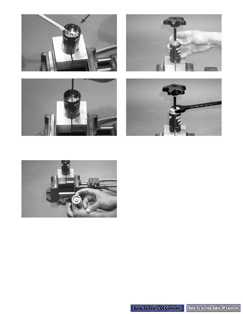
13. Pour out the excess oil from the adjuster assembly;

then grease the tip of the floating piston adjuster

screw using a good quality grease.

AG828

14. Install the adjuster handle making sure the handle

is turned out (counterclockwise) completely.

Tighten securely.

AG829

AG830

15. There must be a 1/4 to 1 turn of free-play on the

handle. If handle free-play is not within specifica-

tions, repeat steps 7-11.

CLEANING AND INSPECTING

1. Inspect all hoses for cracks, kinks, or signs of

damage; then clean all hoses and shock compo-

nents of any contaminated oil.

2. Inspect all shock and reservoir surfaces for signs

of damage.

„

NOTE: All cleaning fluids must be removed com-

pletely before assembling to avoid contamination
of the oil.

3. Inspect all O-rings for cracks or damage. It is rec-

ommended that all O-rings be replaced with new

O-rings any time the shock is disassembled.

4. Clean all parts; then lay all parts on a clean news-

paper.

ASSEMBLING SHOCK AND 

REMOTE RESERVOIR

„

NOTE: When assembling the shock, it is recom-

mended to replace old O-rings with new O-rings.
There is a Shock Rebuild Kit (p/n 1639-770) that
contains all the necessary O-rings for rebuilding
the front arm quick-adjust shock.

1. Secure the shock body in a vise by the lower end

cap eyelet.

9-175

9

2. Lightly grease the shock body and the O-rings on

the outer threaded sleeve; then install the outer

threaded sleeve making sure the fitting on the

outer threaded sleeve aligns with the fitting on the

shock body.

AG831

AG832

AG833

3. Install the spiral retainer on the shock body mak-

ing sure the retainer seats in the retainer groove.

4. While holding the remote reservoir above the

shock body with the hose free of any low spots, fill

the remote reservoir with new shock oil until oil

flows free of air bubbles into the shock body.

AG834

5. Position the remote reservoir below the shock

body; then fill the remote reservoir to the top with

new shock oil. Allow time for air bubbles to dissi-

pate.

6. Install the floating piston with the Allen-head

screw installed in piston. Push piston in until flush

with top of reservoir body; then let reservoir and

hose hang down from shock for a few minutes to

let any air work up and out of the shock. Push the

floating piston all the way into the reservoir. The

shock may overflow with oil. Pull the floating pis-

ton back 2 inches and push back down a couple of

times while keeping the open end of the reservoir

down and below the shock body. This will remove

all the air from the reservoir and hose.

AG849

„

NOTE: Assembling this shock results in oil over-

flowing several times. This is necessary to remove
air from the system.

7. With the floating piston pushed to the bottom of

the reservoir, finish filling the shock body with

new shock oil to the bottom of the threads. Allow

time for all air bubbles to dissipate; then angle the

shock body slightly in the vise.

8. Lightly grease the threads of the shock body and

the piston adjuster O-ring.

„

NOTE: You may proceed with a few small air

bubbles coming from the orifices near the top of
the shock.

9. Set the adjuster piston 1 to 1 1/2 in. from valving

piston while holding the end cap at the top.

9-176

AG835

10. To install the shock rod, align the valve piston

wear ring end gap with the low-speed orifice cut-

away positioning the cutaway so it faces the

upward angle of the shock body which will allow

air to escape. Install the valving piston by pushing

on the shaft eyelet while guiding the piston ring

into the shock body. Push the piston to bottom of

the threads on the inside shock body.

AG836

11. Allow air to dissipate; then stand shock straight up

and fill with oil. Install adjuster piston by pushing

down on adjuster piston until it is just past the ori-

fice in the shock body.

AG837

AG838

„

NOTE: When installing the adjuster piston, push

down only on the adjuster piston. Do not push
down on the shock eyelet.

12. Pour oil into the coupler female end; then connect

hose from the shock body to the adjuster assem-

bly.

AG839

13. While keeping the adjuster and hose below the

shock, turn the adjuster knob in (clockwise) until

oil reaches the top of the shock body free of air

bubbles; then back the adjuster knob off.

„

NOTE: The adjuster knob must remain con-

nected and backed out through the remaining pro-
cedure until the shock has been pressurized;
otherwise, the oil will be trapped on top of the
adjuster piston and the shock rod will appear to be
short and the shock will not function properly.

AG840

9-177

9

14. While holding the shock eyelet to prevent the

shock rod from moving, SLOWLY push down on

the shock rod end cap; then slowly screw in shock

rod end cap to allow air and oil to escape past the

threads of the end cap. Tighten securely.

AG841

15. Install the reservoir end cap into the remote reser-

voir; then install circlip. Pull out on the reservoir

end cap to ensure that the circlip has been properly

seated in its groove.

AG842

AG843

16. Pressurize the shock (refer to Pressurizing

Rebuildable Shocks in this section).

„

NOTE: The shock must be pressurized and de-

pressurized before an accurate piston depth mea-
surement can be taken.

AG844

17. Test the shock by pushing down on the shock shaft

until it bottoms; then release the shaft. The shaft

should return smoothly to the extended position.

„

NOTE: If a soft spot or a mushy area is felt as the

shaft is pushed down, this would indicate air in the
shock body. If there is air in the shock body,
repeat the entire disassembly and assembly pro-
cedure.

18. Clamp the remote reservoir upright in the shock

blocks. Discharge all pressure from the reservoir.

Push the remote reservoir end cap in and remove

the circlip. Remove the remote reservoir end cap.

19. Measure the piston depth from the top of the reser-

voir body to the top of floating piston. Measure-

ment should be within specification (see

Rebuildable Shock Piston Depth Chart in this sec-

tion). If measurement is not correct, pour 1 inch of

shock oil on top of the piston. Remove the Allen-

head screw; then move the piston to the proper

depth and install Allen-head screw with O-ring.

20. Pour out excess oil. Reinstall the end cap and cir-

clips; then pressurize the shock.

21. Install the valve screw in the end of the remote res-

ervoir.

22. Disconnect the adjuster reservoir; then refill the

adjuster reservoir.

FILLING ADJUSTER RESERVOIR

1. Remove the adjuster end cap; then remove the

Allen-head screw from the center of the floating

piston.


Content   ..  172  173  174  175   ..