Snowmobile Arctic Cat (2002 year). Manual - part 172


  Index      Snowmobiles / ATV     Snowmobile Arctic Cat - service manual 2002 year


Search            


Content   ..  170  171  172  173   ..


Snowmobile Arctic Cat (2002 year). Manual - part 172


9-166

Servicing I.F.P.

Style Shocks

„

NOTE: Some illustrations and photographs used

in the following sub-sections are used for clarity
purposes and are not designed to depict actual
conditions.

DISASSEMBLING

1. Remove the shock from the snowmobile.

2. Wash the shock body in parts cleaner; then dry

with compressed air to remove sand and dirt.

3. Place the shock into the Gas Shock Retaining

Blocks (p/n 0644-142); then remove shock eyelet

mounting axle and bushings from end cap.

„

NOTE: A paper shop towel between the shock

body and retaining blocks will help prevent scuff-
ing of the shock body.

AP110DA

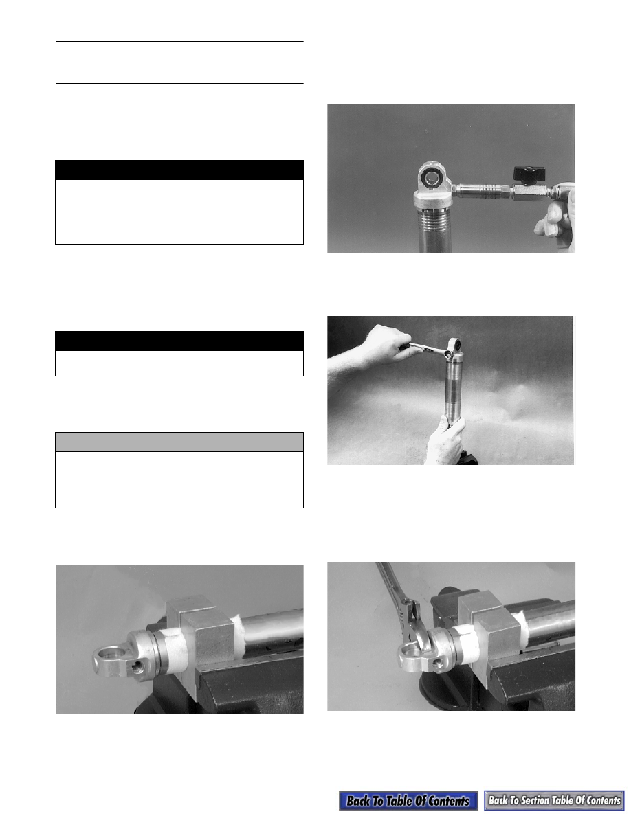
4. Remove the screw from the bladder housing on the

bottom of the shock. Discharge all the pressure

from the shock using the Shock Inflation Needle

(p/n 0644-158). Open the valve in filler handle

until all pressure is released.

AG335

5. Using a 9/16-in. wrench, remove the brass bladder

housing from the lower end cap. Account for an

O-ring.

AP014

6. Using a large adjustable wrench (12-in. or 14-in.),

remove the end cap.

„

NOTE: 1994 and older shocks have Loctite on

the lower end cap. Heating the lower end cap may
be necessary. Use care not to overheat.

AP016DA

7. Using a 1-in. open end wrench, loosen the shock

shaft bearing cap a couple of turns.

! WARNING

Before servicing a gas shock absorber, first dis-
charge all pressure from the shock. Remove the
screw from the bottom of the shock and insert the
Shock Inflation Needle (p/n 0644-158). Open valve
until all pressure is released. Failure to do this may
cause personal injury.

! WARNING

When using compressed air to dry components,
always wear safety glasses.

! CAUTION

It is important that the Gas Shock Retaining
Blocks (p/n 0644-142) are used during both
disassembly and assembly. Any other method of
securing the shock body during these
procedures may deform the shock body cylinder.

9-167

9

„

NOTE: Do not remove the bearing cap at this

time.

AP026

8. Turn the shock so that the open end is up. Then

remove the Allen-head screw located in the center

of the floating piston. Account for a small O-ring.

AP022

9. Using a pair of pliers, pull the floating piston

assembly out of the shock body. Account for a pis-

ton ring and an O-ring.

10. Pour the oil out of the shock body.

11. Unscrew the shaft bearing cap and lift the shaft

assemble from the shock body.

AP027

12. Clean the inside of the shock body using clean

parts-cleaning solvent. Blow dry using com-

pressed air.

„

NOTE: Do not lay shock parts on a rag as it may

transfer lint to the parts causing internal shock
problems.

13. Remove the piston ring from the piston. Loosen

(but do not remove) the lock nut from the bottom

of the shock shaft; then clean the piston area with

clean parts-cleaning solvent to remove dirt or for-

eign material from between the valves. Dry the

piston and valves completely using compressed

air.

„

NOTE: If for some reason the piston must be

removed from the shock shaft, it must be installed
with its large seven slots located next to the lock
nut side of the shock shaft.

AP051

AP028

„

NOTE: If shock valving must be removed for

cleaning, remove all valving as a complete assem-
bly and place on a 5/16 x 3-in. cap screw to keep in
proper order. Note which side is the top side for
assembly purposes.

! WARNING

When using compressed air to dry components,
always wear safety glasses.

! WARNING

When using compressed air to dry components,
always wear safety glasses.

9-168

AP032

14. Items to inspect:

A. Shock shaft for straightness, nicks, or burrs.

B. Shaft bearing end cap — clean, inspect, or

replace.

C. Inside of shock body for scratches, burrs, or

excessive wear.

D. Piston rings for cuts, chipped or nicked edges,

or excessive wear.

E. O-rings for nicks, cuts, or cracks.

F. Valves for kinks or waves.

G. Rubber damper (ski shocks only) for chipping,

cracking, or being missing.

15. Items to replace:

A. Bleed screw O-ring on the floating piston.

B. Shock shaft bearing cap if any signs of oil leaks

or damage.

C. Any part worn or damaged.

„

NOTE: For shaft, shaft eyelets, or shaft bearing

cap replacement, see Shaft Eyelet or Bearing Cap
and Shaft Seal sub-section.

ASSEMBLING

1. Place the shock shaft eyelet into the vise; then

assemble valves and piston and tighten the lock

nut to 2.1-2.8 kg-m (15-20 ft-lb).

2. Place the shock body between the two Gas Shock

Retaining Blocks (p/n 0644-142) and secure in a

vise.

3. Apply a light coat of oil on the O-ring and piston

ring and install piston into shock body.

AP033

4. Place the shaft bearing cap into the body and

tighten securely.

AP026

5. Loosen vise and reposition the shock body and

retaining blocks so the bottom of the shock body is

“up” and in a vertical position. Extend the shock

shaft fully and fill the shock body with Shock Oil

(p/n 1639-245) to within 1-1 1/2-in. from the top.

! CAUTION

DO NOT OVER-TIGHTEN. If excessive torque is
applied, damage to the piston and valves will
occur.

! CAUTION

It is important that the Gas Shock Retaining
Blocks (p/n 0644-142) are used during both
disassembly and assembly. Any other method of
securing the shock body during these
procedures may deform the shock body cylinder.

9-169

9

6. Slowly move the shock shaft up and down a few

times keeping the piston under oil at all times.

This is to remove the air from under the piston.

Extend the shock shaft fully; then fill the shock

body with oil to within 1/2-3/4-in. from the top.

„

NOTE: After filling the shock body with oil, allow

5 minutes for all air bubbles to rise to the top.

7. Apply a light coat of oil on the floating piston ring

and O-ring and install the floating piston in the

shock body.

AP023

„

NOTE: Depending on which shock absorber is

being worked on, adjust the piston location tool to
the specification indicated in the Rebuildable
Shock Piston Depth Chart in this section.

AP050

8. Attach the Shock Piston Location Tool (p/n 0644-

169) to the piston by placing its slotted end over

the flats on the top of the piston and giving the tool

a quarter turn. Pull gently on the tool to make sure

it is secure to the piston.

AG339

9. Using the tool as a handle, push the piston down

into the shock body until the adjustment knob

comes in contact with the shock body. Give the

tool a quarter turn to free it from the piston. The

piston should now be located correctly.

729-085C

„

NOTE: As the floating piston is pushed into the

shock absorber body, air and excess oil will come
out through the hole in the piston. If no oil comes
out through the hole in the piston, remove the pis-
ton and add more oil to the shock body.

10. Install the Allen-head screw and O-ring into the

bottom of the floating piston. While securing the

piston with a 9/16-in. wrench, tighten the Allen-

head screw.

AP020

11. Pour out the excess oil from the shock body.

12. Install the lower end cap on the shock body.


Content   ..  170  171  172  173   ..