Snowmobile Arctic Cat (2002 year). Manual - part 177
9-186
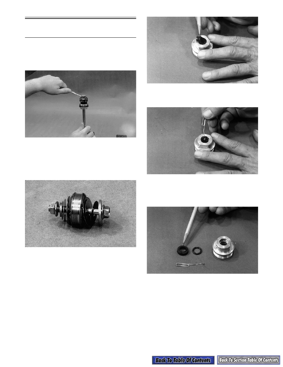
Bearing Cap
and Shaft Seal
REMOVING AND DISASSEMBLING
1. With shaft assembly removed from shock body,
clamp shaft eyelet in vise and remove the lock nut.
AP028
2. Lift the piston valve assembly.
NOTE: When removing the piston and valve
plates from the shock shaft, place the piston
assembly on a 5/16 x 3-in. cap screw and secure
with a nut to keep the assembly in its proper order.
AP032
3. Remove the bearing cap (on front arm adjuster
shocks, remove the adjuster piston and a spacer
washer first).
4. Remove the outer plastic wiper; then remove the
inner rubber wiper from the bearing cap.
AG257
5. Using a small paper clip bent on one end, remove
the inner O-ring.
AG258
ASSEMBLING AND INSTALLING
1. Install new O-ring and inner rubber wiper into the
shaft bearing cap; then install outer plastic wiper.
AG259
2. Inspect the shoulder or step of the shaft for sharp
edges or a burr. Smooth up with #400 grit sand
paper or emery cloth.
3. Put Bearing Cap Installation Tool (p/n 0644-268)
over the threaded end of the shaft.