Snowmobile Arctic Cat (2002 year). Manual - part 162


  Index      Snowmobiles / ATV     Snowmobile Arctic Cat - service manual 2002 year


Search            


Content   ..  160  161  162  163   ..


Snowmobile Arctic Cat (2002 year). Manual - part 162


9-126

AG322D

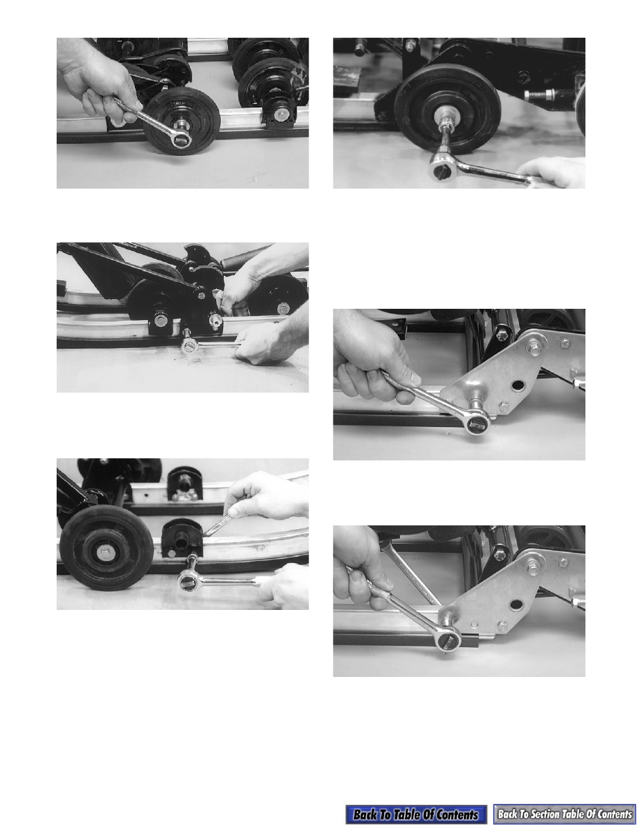
5. Remove the three cap screws and lock nuts secur-

ing the front arm bracket to the slide rail.

AG323

6. Remove the two cap screws and lock nuts securing

the center inner idler wheel bracket to the slide

rail.

AG390

7. Remove the cap screws and large flat washers

securing the center pivot idler wheels; then

remove the idler wheels.

AG600

8. Remove the two cap screws and lock nuts securing

the auxiliary wheel bracket.

9. Remove the cap screw, lock nut, and two washers

securing the spring block.

10. Remove the long cap screw securing the lower

rear arm assembly to the slide rails.

AG332D

11. Remove two cap screws securing each of the artic-

ulating frame brackets; then remove the articulat-

ing skid frame. Account for spacers.

AG611D

12. Remove the cap screw and nut securing the spring

tension block to the slide rail. Account for the

washers.

13. With all bracket hardware removed, pull the slide

rail slowly forward and out of all brackets.

9-127

9

INSPECTING

„

NOTE: Whenever a part is worn excessively,

cracked, or damaged in any way, replacement is
necessary.

1. Inspect the slide rail for cracks or unusual bends.

2. Inspect the wear strip for wear. The wear strip

must be 10.7 mm (0.42 in.) thick or thicker. If the

wear strip measurement is less than specified,

replacement of both wear strips is necessary.

0727-726

INSTALLING

1. Starting in front, place the back end of the slide

rail into the first bracket and slowly work it back

through all brackets. Install the cap screws and

lock nuts securing the slide rail to the brackets.

Tighten all slide rail hardware to the recom-

mended torque specifications.

2. Place the spring tension block into position on the

slide rail and secure with a cap screw, two wash-

ers, and a lock nut. Tighten securely ensuring free

movement of the spring tension block.

3. Place the articulating skid frame into position,

install spacers, and secure with four cap screws

and lock nuts. Tighten to 2.4 kg-m (17 ft-lb).

4. Secure the lower rear arm assembly with the long

cap screw, lock nut (threads coated with red Loc-

tite #271), and washers. Tighten to 3.2 kg-m

(23 ft-lb).

5. Place the center pivot idler wheels into position

and secure each with a large flat washer and cap

screw. Tighten to 3.2 kg-m (23 ft-lb).

6. Align the auxiliary wheel bracket, center idler

wheel bracket, front arm bracket, and front idler

wheel bracket with the appropriate holes in the

skid frame. Secure each with cap screws and lock

nuts. Tighten to 2.4 kg-m (17 ft-lb).

7. Install the outer idler wheel on the front arm

bracket. Secure with a cap screw (coated with red

Loctite #271) and lock nut. Tighten to 2.4 kg-m

(17 ft-lb).

AG322D

8. Place the shock pads into position and secure with

pins and push nuts.

9. Install both front crossbraces between the slide

rails. Secure with four cap screws (coated with red

Loctite #271). Tighten to 2.4 kg-m (17 ft-lb).

„

NOTE: Be sure to place the forward crossbrace

tube through the limiter straps.

AG301

10. Place the end cap onto the rail and secure with the

cap screw, washer, and lock nut. Tighten to

1.1 kg-m (8 ft-lb).

9-128

Installing Skid Frame

1. Place a piece of cardboard on the floor to protect

against scratching and tip the snowmobile onto

one side.

2. Pull the track away from the tunnel and spread

open; then place the skid frame into the track.

Slide the inner axles through the upper and rear

arms of the skid frame.

„

NOTE: The proper front arm tunnel mounting

hole to use will depend on which position the front
arm brackets are mounted in on the slide rails. If
the front arm brackets are positioned in the rear
rail mounting holes, use the upper rear mounting
holes.

3. Position the front of the skid frame into the tunnel

and align the front arm with the appropriate

mounting hole in the tunnel. Slide the lock washer

onto the cap screw; then secure the front arm to the

tunnel with the cap screw and lock washer. Thread

the cap screw in only half way. DO NOT

TIGHTEN AT THIS TIME.

„

NOTE: To aid in centering the front arm with the

holes in the tunnel, position the skid frame and
track at a 45° angle to the bottom of the tunnel.

4. Slide the skid frame and track into the tunnel.

5. Tip the snowmobile onto the opposite side and

install the remaining front arm cap screw and lock

washer. Use the same procedure as step 3.

6. Align the rear arm with the forward mounting hole

in the bracket. Secure the rear arm with a cap

screw and lock washer. DO NOT TIGHTEN AT

THIS TIME.

„

NOTE: Do not tighten any of the four cap screws

until all have been started. To obtain proper align-
ment of the rear arm, pry the arm in the proper
direction until alignment is obtained.

7. Again tip the snowmobile onto the opposite side

and install the remaining rear arm cap screw and

lock washer. Follow the same procedure as in step

6.

8. Tighten all four skid frame mounting cap screws

to 3.2 kg-m (23 ft-lb).

9. Check track tension; adjust as necessary (see

Track Tension in this sub-section).

10. Check track alignment; adjust as necessary (see

Track Alignment in this sub-section).

Track Tension

CHECKING DEFLECTION

1. Tip the snowmobile on its side.

2. Hook a spring scale around a track clip at mid-

span; then pull the track down with the scale to 9

kg (20 lb) and measure the distance between the

bottom of the wear strip and the inside surface of

the track clip. Track deflection must be within

specifications.

729-429A

„

NOTE: If the track is new, it will stretch slightly

and take a “set” within the first 300 to 500 miles of
operation.

ADJUSTING DEFLECTION

1. Place the snowmobile on a shielded safety stand.

Check to make sure the track is 2-3 in. off the

floor.

2. If the measurement is not as specified, loosen the

jam nuts of the adjusting bolts.

! WARNING

Turn all switches to the OFF position.

Rear Suspension 
Style

Setup

Tension

After Break-In

Tension

FasTrack w/o Torque 

Sensing Link

19-25 mm

(3/4-1 in.)

25-32 mm

(1-1 1/4 in.)

FasTrack w/Torque 

Sensing Link 

(121 in. Track)

32-38 mm

(1 1/4-1 1/2 in.)

38-44 mm

(1 1/2-1 3/4 in.)

FasTrack w/Torque 

Sensing Link 

(136 in. Track)

38-44 mm

(1 1/2-1 3/4 in.)

50.8-57.2 mm

(2-2 1/4 in.)

9-129

9

0727-456

3. If the measurement is more than specified, tighten

the adjusting bolts. If the measurement is less than

specified, loosen the adjusting bolts. When the

measurement is within specification range, lock

the adjustment by bottoming the jam nuts against

the axle housings.

„

NOTE: Vigorously push the underside of the

track up and down. Track must not hit the top of
the tunnel or slap the skid frame.

4. After correct track tension is obtained, check track

alignment (see Track Alignment in this sub-sec-

tion).

„

NOTE: Track tension and track alignment are

interrelated; always check both even if only one
adjustment seems necessary. Always establish
correct track tension before checking and/or
adjusting alignment.

Track Alignment

„

NOTE: Proper track alignment is when the rear

idler wheels are equidistant from the inner drive
lugs on the inside surface of the track.

CHECKING

1. Using a shielded safety stand, raise the rear of the

snowmobile off the floor making sure the track is

free to rotate.

2. Start the engine and accelerate slightly. Use only

enough throttle to rotate the track several revolu-

tions. SHUT THE ENGINE OFF.

„

NOTE: Allow the track to coast to a stop. DO

NOT apply the brake because it could produce
inaccurate alignment conditions.

3. When the track stops rotating, check the relation-

ship of the rear idler wheels and the inner track

drive lugs. If the distance from the idler wheels to

the inner track drive lugs is the same on both sides,

no adjustment is necessary.

725-070A

„

NOTE: If the distance from the idler wheels to

the inner track drive lugs is not the same on both
sides, an adjustment is necessary.

ADJUSTING

1. On the side of the track which has the inner drive

lugs closer to the rear idler wheel, loosen the

adjusting bolt jam nut; then rotate the adjusting

bolt clockwise 1-1 1/2 turns.

2. Continue to check the track alignment and make

the necessary adjustments until proper alignment

is obtained.

3. After proper track alignment is obtained, lock the

adjusting bolt jam nut against the axle housing.

„

NOTE: Make sure correct track tension is main-

tained after adjusting track alignment.

„

NOTE: Field test the track under actual condi-

tions and, after the field test, recheck track align-
ment and track tension; adjust as necessary.

Overload Springs

To either engage or disengage the spring tension

blocks, use the Spring Block Tool, a spark plug socket,

and a screwdriver and rotate the spring block to the

desired position. Both spring blocks must be in the

same position (either engaged or disengaged).

! WARNING

The tips of the skis must be positioned against a
wall or similar object for safety. Keep hands, feet,
and clothing away from moving components.


Content   ..  160  161  162  163   ..