Snowmobile Arctic Cat (2002 year). Manual - part 149
9-74
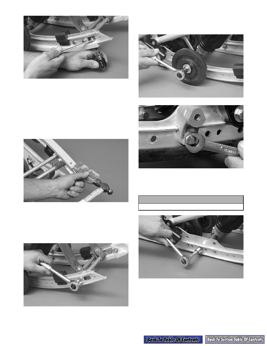
AG509D
3. Using a pipe wrench and starting from either end,
hook the edge of the wear strip with the pipe
wrench jaw and twist the wear strip off the slide
rail. Move the pipe wrench 7.5 cm (3 in.) and
again twist the wear strip off the rail. Repeat this
procedure until the wear strip is free of the rail.
NOTE: The wear strip can also be driven off the
slide rail; however, it is quicker to use the pipe
wrench.
AG510D
4. Remove the cap screws securing the crossbraces to
the slide rail.
NOTE: On models with remote adjuster, cut the
cable ties securing the hose to the slide rail and
arm.
AG511D
5. Remove the cap screws and lock nuts securing the
front outer idler wheel and the idler wheel mount-
ing block. Account for flat washers and an axle.
AG512D
AG686D
6. Remove the cap screws and lock washers securing
the front shock mount axle. Discard the cap
screws.
AG514D
7. Remove the short spring leg from the adjusting
cam.
! CAUTION
It may be necessary to heat the cap screws.