Snowmobile Arctic Cat (2002 year). Manual - part 147


  Index      Snowmobiles / ATV     Snowmobile Arctic Cat - service manual 2002 year


Search            


Content   ..  145  146  147  148   ..


Snowmobile Arctic Cat (2002 year). Manual - part 147


9-66

AG556D

AG682D

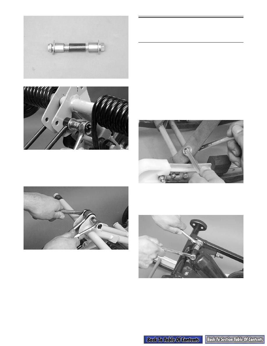
4. Place the upper shock eyelet with bushings

between the idler arm brackets making sure the

spacer is properly positioned between the brack-

ets. Secure with a cap screw and lock nut. Tighten

to 3.2 kg-m (23 ft-lb).

AG467D

„

NOTE: Do not over-tighten the shock absorber

cap screw as the shock eyelet must be free to
pivot.

5. Grease the idler arm and rear arm grease fittings

with a low-temperature grease.

6. Install the rear upper idler wheels, rear springs,

and offset pivot idler (see Rear Upper Idler

Wheels/Rear Springs in this sub-section).

Front Arm/Front Shock 

Absorber/Front Inner 

Idler Wheels

„

NOTE: The skid frame must be removed for this

procedure (see Removing Skid Frame in this sub-
section), and the rear springs must be removed
from the adjusting cams.

REMOVING

„

NOTE: On models with remote adjuster, cut the

cable ties securing the front shock absorber hose
to the front arm.

1. Remove the lower cap screws and lock nuts secur-

ing the limiter straps to the rail support. Account

for flat washers.

AG632D

2. Remove the cap screw and lock nut securing the

upper front shock absorber eyelet to the front arm.

Pull the shock eyelet free of the bracket. Account

for a serrated axle.

AG582D

3. Remove the cap screws and lock nuts securing the

front arm to the front arm mounting brackets.

9-67

9

AG565D

4. Remove the front arm and account for the two

front arm spacers.

AG485D

5. Remove the cap screws securing the front outer

idler wheels to the idler wheel mounting block.

Account for a lock nuts, axles, inserts, and flat

washers.

AG566D

6. Remove the cap screw and lock washer securing

one side of the shock mount axle. Clean the Loc-

tite from the axle threads and cap screw threads;

then reinstall the cap screw. Remove the opposite-

side cap screw and lock washer; then clean the

Loctite from the axle threads and cap screw

threads. Remove the first cap screw and washer;

then remove the axle and account for spacers, flat

washers, and shock bushings. Discard the cap

screws.

„

NOTE: New cap screws must be used when

installing the shock mount axle.

AG567D

AG568D

„

NOTE: On models with remote adjuster, loosen

the three Allen-head screws securing the remote
reservoir; then slide the reservoir assembly over
and remove the reservoir with hoses.

! CAUTION

It may be necessary to heat the cap screws. Care
must be taken to prevent damage to other
components.

9-68

AG591D

7. Using a plastic mallet, tap the axle from the lower

shock eyelet.

INSPECTING

„

NOTE: Whenever a part is worn excessively,

cracked, or damaged in any way, replacement is
necessary.

1. Inspect all front arm weldments for cracks or

unusual bends.

2. Closely inspect all tubing for cracks or unusual

bends.

3. Inspect the bearings, bushings, and front arm spac-

ers for wear or damage.

4. Inspect the two rear track guide bumpers. If worn,

drill out the rivets securing the bumpers to the arm

and replace with new bumpers.

AG486D

5. Inspect the shock absorber for any signs of oil

leakage especially at the point where the shock

shaft enters the shock body.

6. Inspect the shock absorber eyelet welds (at each

end) for any cracks, signs of separation, or for

unthreading.

7. Inspect the shock absorber and reservoir hoses (on

models with remote adjuster) for damage.

INSTALLING

1. On models with remote adjuster, place the remote

reservoir into position making sure the hose is

directed to the left-side of the skid frame. Secure

with the three Allen-head screws coated with red

Loctite #271. Tighten the outside screws first.

„

NOTE: The center Allen-head screw will not bot-

tom on its shoulder when tightened. It bottoms on
the cross-shaft to hold the assembly centered.

AG591D

2. Install the axle into the lower shock eyelet bushing

assembly. Apply grease to the axle; then install the

spacers.

AG568D

3. Place the shock mount axle into position on the

skid frame making sure the spacers and washers

are properly positioned. Secure with new cap

screws (coated with green Loctite #609) and wash-

ers. Tighten to 4.2 kg-m (30 ft-lb).

! CAUTION

Care must be taken when removing the remote
reservoir that the hoses are not kinked or
damaged.

9-69

9

AG567D

4. Position the front arm with spacers into the mount-

ing brackets. Secure with cap screws and lock

nuts. Tighten to 4.2 kg-m (30 ft-lb).

AG565D

5. Secure the upper shock eyelet and serrated axle in

the appropriate mounting hole of the front arm

(standard arm mounting position). Secure with a

cap screw and lock nut. Tighten to 3.2 kg-m

(23 ft-lb).

AG564D

6. Secure the limiter straps with cap screws, washers,

and lock nuts. Tighten to 1.1 kg-m (8 ft-lb).

AG480D

„

NOTE: On models with remote adjuster, secure

the shock absorber hose to the left upper arm and
slide rail using cable ties. Pull the cable ties tight
to prevent the hose from sliding. Compress the
front arm to assure the hose does not interfere
with the suspension.

AG590D

7. Secure the front outer idler wheels to the idler

wheel mounting blocks with cap screws, flat

washers, inserts, axles, and lock nuts. Tighten to

3.2 kg-m (23 ft-lb).

AG572D


Content   ..  145  146  147  148   ..