Snowmobile Arctic Cat (2002 year). Manual - part 148


  Index      Snowmobiles / ATV     Snowmobile Arctic Cat - service manual 2002 year


Search            


Content   ..  146  147  148  149   ..


Snowmobile Arctic Cat (2002 year). Manual - part 148


9-70

AG512D

Rear Shock Absorber 

and Shock Links

„

NOTE: Before removing the skid frame by using

the Rear Suspension Spring Tool (p/n 0144-311),
remove the spring from the adjusting cam.

„

NOTE: The skid frame must be removed for this

procedure (see Removing Skid Frame in this sub-
section).

DISASSEMBLING

1. Remove the rear inner idler wheels (see Rear Inner

Idler Wheels in this sub-section).

AG592D

2. Note the hole location that the spring slides are in;

then remove the cap screws and flat washers

securing the spring slides to the rails. Account for

slide blocks.

AG662D

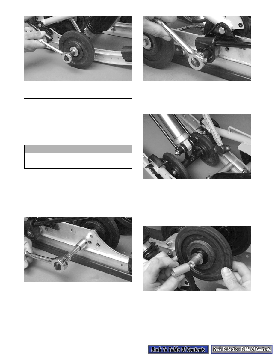
3. Tap the idler wheel assembly rearward until it

clears the mounting brackets; then lift the idler

wheel assembly upward until the shaft clears the

rails.

AG569D

„

NOTE: Lay components out in order as they are

removed.

4. Remove the spacer, washer, idler wheel with

inserts, washer, and inner bushing. Repeat the

same procedure on the other side of the shock

pivot bracket. Remove the idler wheel axle.

AG492D

! CAUTION

Care must be taken when removing the spring
from the adjusting cam or damage or injury
could result.

9-71

9

AG663D

5. Disengage the shock absorber at the lower eyelet.

Account for washers, axle links, bushings, shock

sleeve, cap screw, and a lock nut.

AG596D

AG664D

6. Disengage the shock absorber at the upper eyelet

and remove the shock absorber. Account for a

sleeve, cap screw, lock nut, and bushings.

AG657D

AG665D

CLEANING AND INSPECTING

„

NOTE: Whenever a part is worn excessively,

cracked, or damaged in any way, replacement is
necessary.

1. Clean shock pivot and idler wheel axle in part-

cleaning solvent. Dry with compressed air.

2. Clean the idler wheel bearings with a clean cloth.

3. Closely inspect the torque link arm and axles for

wear, bends, or damaged splines at either end.

4. Inspect the idler wheels for signs of cracking,

wear, or outer rubber separation from plastic

wheel.

5. Rotate the idler wheel bearings (by hand) and

inspect for any signs of binding or roughness.

6. If a bearing must be replaced, use this procedure.

A. Remove the snap ring.

! WARNING

Always wear an approved pair of safety glasses
when using compressed air.

! CAUTION

Do not remove the bearing unless it is absolutely
necessary. The bearing will be damaged during
removal.

9-72

B. Using a hydraulic press, press the bearing out

the inside of the wheel.

C. Press the new bearing (on its outer race) into

the idler wheel.

AG538D

D. Install the snap ring making sure the “sharp

side” is directed away from the bearing.

AG539D

7. Inspect the shock absorber for any signs of oil

leakage especially at the point where the shock

shaft enters the shock body.

8. Inspect the rubber shock bushings located in the

shock absorber eyelets for cracks or deterioration.

9. Inspect the shock absorber eyelet welds (at each

end) for any cracks or signs of separation.

10. Inspect the welds securing the eyelets of the shock

links for cracks or signs of separation. Either weld

the eyelet or replace the shock link.

11. Inspect the axle surfaces for any signs of corro-

sion. If corrosion is found, lightly buff the surface

of the axle with #400 wet-or-dry sandpaper; then

apply a light coat of grease.

ASSEMBLING

1. Secure the rear shock links and the lower shock

absorber eyelet to the shock pivot bracket. Place

the bushings and shock sleeve into the shock eye-

let; then install the axle links into the rear shock

links. Secure the assembly by installing a cap

screw and flat washer through the shock link

assembly, shock pivot bracket and shock eyelet

assembly, shock link assembly, and a flat washer.

Secure the assembly with a lock nut. Tighten to

3.2 kg-m (23 ft-lb).

AG595D

AG596D

2. Secure the shock absorber to the idler arm with

bushings, sleeve, lock nut, and a cap screw.

Tighten to 3.2 kg-m (23 ft-lb).

AG657D

9-73

9

3. Apply a thin coat of low-temperature grease to the

bushing and idler wheel axle and slide the bushing

and axle into the shock pivot bracket. Have equal

amounts of the axle exposed on either side of the

bracket tube.

AG597D

4. Slide a washer onto the axle; then install an idler

wheel (with its larger bearing insert side facing the

shock pivot), washer, and spacer. Repeat the same

procedure on the other side of the shock pivot

bracket.

AG492D

5. Lower the idler wheel assembly down between the

rails. Align the axle with the mounting hole just

below the front arm mounting brackets (as noted

during disassembly). Secure the spring slides

(with spring legs in position), slide blocks, and

front inner idler wheel axle assembly to the rails.

Tighten to 3.2 kg-m (23 ft-lb).

AG662D

6. Secure the rear inner idler wheel axle assembly

(see Rear Inner Idler Wheels in this sub-section).

AG592D

Slide Rails

„

NOTE: The skid frame must be removed for this

procedure (see Removing Skid Frame in this sub-
section).

REMOVING

„

NOTE: When it is necessary to replace one or

both slide rails, it is recommended that one slide
rail be removed at a time. The remaining slide rail
will then hold the crossbraces, axles, and brackets
in their correct assembly order. Always mark the
mounting hole locations during disassembly to
speed up the assembly process and to prevent any
damage. This method is much quicker than to
completely disassemble the entire skid frame. To
replace either rail, use the following procedure.

1. Remove the end cap from the slide rail. Account

for a cap screw, lock nut, and two flat washers.

AG506D

2. Remove the machine screw and lock nut securing

the wear strip to the front of the slide rail.


Content   ..  146  147  148  149   ..