Snowmobile Arctic Cat (2002 year). Manual - part 125


  Index      Snowmobiles / ATV     Snowmobile Arctic Cat - service manual 2002 year


Search            


Content   ..  123  124  125  126   ..


Snowmobile Arctic Cat (2002 year). Manual - part 125


8-58

2. Apply green Loctite #609 to the rear mounting cap

screw with washer and install. DO NOT

TIGHTEN AT THIS TIME.

AF460D

3. Apply a small amount of grease to the alignment

ball and install into the front of the caliper. Apply

green Loctite #609 to the front cap screw with

washer; then install and tighten both cap screws to

4.2 kg-m (30 ft-lb).

AF293D

AF458D

4. Place the brake cable into the rear slot of the brake

cable bracket and tighten securely.

AF462D

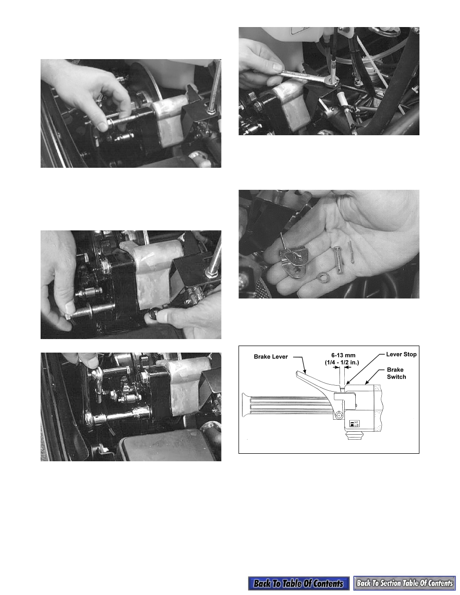
5. Insert the cable end into the rear slot of the clevis.

Install the pin through the clevis and actuator arm;

then install the washer. Install a new cotter pin into

the clevis pin and spread the cotter pin.

AF340

6. Pull out on the quick-adjust knob and turn

clockwise until there is 6-13 mm (1/4-1/2 in.) free-

play at the brake lever.

0727-451

7. Set the brake lever lock; then securely tighten the

jam nut on the upper mounting cap screw.

8-59

8

AF298

8. Release the brake  lever lock and recheck the

brake lever free-play (adjust as needed); then place

the recoil starter rope into the guide portion of the

brake cable bracket.

ADJUSTING BRAKE LEVER TRAVEL

1. Rotate the brake disc alternately forward and

backward while slowly compressing the brake

lever.

2. At the point where the disc is locked, check the

distance between the brake lever and lever stop.

The distance must be within a range of 6-13 mm

(1/4-1/2 in.).

0727-451

3. To decrease brake lever travel (set up brake), pull

out on the spring-loaded quick-adjust knob and

rotate the knob clockwise periodically checking

the brake lever travel distance until the correct

travel distance is attained. Once the correct brake

lever travel has been obtained, release the knob

into a secured position.

„ NOTE: If the quick-adjust knob has reached its
maximum adjustment (cannot be rotated any fur-
t h e r   c l o c k w i s e ) ,   b o t h   b r a k e   p a d s   m u s t   b e
replaced.

0730-151

4. To increase brake lever travel (loosen the brake),

pull out on the quick-adjust knob and rotate the

knob counterclockwise periodically checking the

brake lever travel. Once the desired brake lever

travel is obtained, release the knob into a secured

position.

REPLACING BRAKE PADS

1. Using a 1/2-in. socket, remove the front brake

assembly guide pin. Slowly pull the pin from the

assembly and catch the alignment ball as it drops

from the hole in the front of the caliper assembly.

2. Remove the rear guide pin; then slide the brake

caliper assembly forward free of the brake disc.

3. Remove the stationary brake pad from the caliper

assembly.

4. Tip the caliper on its side and allow the movable

brake pad to drop free of the caliper assembly.

5. Place the new movable brake pad into position;

then temporarily secure with a rubber band to hold

it in place.

6. With the backing plate in position (wide tab

positioned between the snap ring ears), install the

stationary brake pad making sure the notch in the

pad is aligned with small tab of the backing plate.

Using a rubber band, temporarily secure the pad.

! WARNING

Before making any adjustment, make certain the
brake quick-adjust knob isnt hot. If the snowmobile
has just been used, allow some time for the knob to
cool or burns may result.

! WARNING

DO NOT attempt to adjust the brake with the flange
nuts on the brake cable bracket. Incorrect brake
adjustment may occur causing possible brake fail-
ure.

! CAUTION

The brake pads must be replaced as a set. Do not
under any circumstances ever replace only one
of the brake pads.

8-60

7. Place the brake assembly back into position over

the brake disc. Apply green Loctite #609 to the

rear guide pin; then install the rear guide pin.

8. Insert the alignment ball into the hole at the front

of the caliper, apply green Loctite #609 to the

front guide pin, and install the front guide pin.

Tighten the two alignment pins to 4.2 kg-m

(30 ft-lb). Cut and remove the two rubber bands.

„ NOTE: When new brake pads have been
installed, a burnishing process is required. Drive
the snowmobile slowly and compress the brake
lever repeatedly until the pads just start to heat up;
then allow them to cool down. This process stabi-
lizes the pad material and extends the life of the
pads.

Brake Control

(Mechanical/Quick-Adjust)

REMOVING AND DISASSEMBLING

1. Remove the Phillips-head screws securing the

handlebar pad to the handlebar.

AL136D

2. Remove the retaining ring, washer, and pin

securing the brake lever.

AL137D

AL138D

3. Loosen the jam nut securing the brake cable to the

brake cable bracket.

AF462D

4. Disconnect the brake cable from the seat in the

brake lever and remove the lever; then slide the

brake cable free of the brake control.

AL140D

5. Remove the brake lever from the brake control

housing.

6. Remove the four screws securing the console; then

raise the console to gain access to the main wiring

harness.

7. Disconnect the brake control wiring harness from

the main wiring harness.

8-61

8

AL141D

8. Cut the cable ties holding the wiring harnesses and

cables to the steering post noting their locations

for installing purposes.

9. Using a sharp knife, cut the grip off the handlebar;

then using a solvent, clean adhesive from the

handlebar.

10. Remove the machine screw securing the brake

control to the handlebar; then slide the brake

control off the handlebar.

AL143D

ASSEMBLING AND INSTALLING

735-820A

1. Slide the brake control onto the handlebar and

secure with the machine screw.

AL143D

2. Connect the wiring harness at the console.

3. Connect the brake control wiring harness to the

main wiring harness; then secure the harnesses

with cable ties.

Key

1. Spring
2. Brake Cable
3. Brake Lever
4. Axle
5. Knob
6. Handwarmer Control
7. Machine Screw
8. Spring
9. Self-Tapping Screw

10. Retaining Ring
11. Cover Plate

12. Actuator
13. Pin
14. Dimmer Switch
15. Washer
16. Retaining Ring
17. Grip
18. Housing
19. Flange Nut
20. Brake Control Assy
21. Handwarmer Element


Content   ..  123  124  125  126   ..