Snowmobile Arctic Cat (2002 year). Manual - part 100
7-12
INSPECTING
NOTE: Whenever a part is worn excessively,
cracked, or damaged in any way, replacement is
necessary.
1. Inspect the ski for cracks or deterioration.
2. Inspect the ski for abnormal bends or cracks.
3. Inspect the wear bar for wear.
4. Inspect all hardware and the spindle bushings for
wear and damage.
5. Inspect the rubber damper for damage or wear.
INSTALLING
0736-423
0736-533
1. Position the ski over the saddle.
2. Apply a low-temperature grease to the non-
threaded portion of the cap screw; then slide the
cap screw (with washer as required) through the
ski and saddle accounting for the rubber damper.
NOTE: Install the cap screw so the lock nut will
be located to the inside of the ski.
3. Apply red Loctite #271 to the threads of the cap
screw; then tighten the lock nut (with washer as
required) to 6.2 kg-m (45 ft-lb).
4. Place the cotter pin into the ski cap screw and
spread the pin.
Ski
(120 cc)
REMOVING
1. Place the cap screw and lock nut securing the ski
to the spindle.
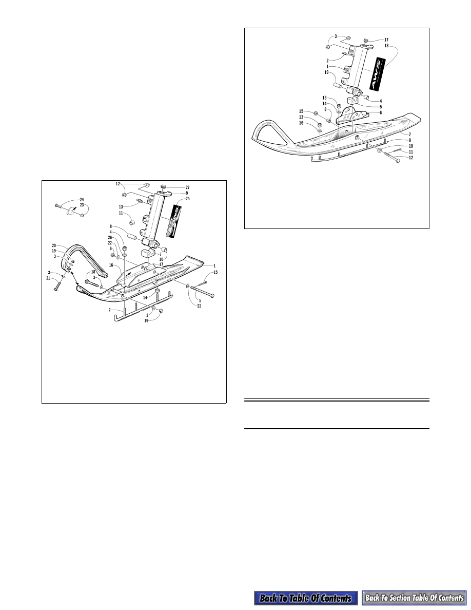
KEY
1. Ski
2. Wear Bar
3. Washer
4. Lock Nut
5. Cap Screw
6. Lock Nut
7. Damper
8. Spindle Axle
9. Spindle
10. Bearing
11. Bearing
12. Spindle Insert
13. Grease Fitting
14. Spacer
15. Cotter Pin
16. Ski Saddle
17. Ski Saddle
Insert
18. Cap Screw
19. Lock Nut
20. Plastic Handle
21. Cap Screw
22. Washer
23. Lock Nut
24. Machine Screw
25. Decal
26. Washer
27. Spindle Cap
KEY
1. Spindle
2. Grease Fitting
3. Spindle Insert
4. Bearing
5. Damper
6. Ski Saddle
7. Ski
8. Ski Insert
9. Wear Bar
10. Washer
11. Cotter Pin
12. Cap Screw
13. Lock Nut
14. Washer
15. Lock Nut
16. Washer
17. Spindle Cap
18. Decal
19. Axle