Snowmobile Arctic Cat (2002 year). Manual - part 101


  Index      Snowmobiles / ATV     Snowmobile Arctic Cat - service manual 2002 year


Search            


Content   ..  99  100  101  102   ..


Snowmobile Arctic Cat (2002 year). Manual - part 101


7-16

A028

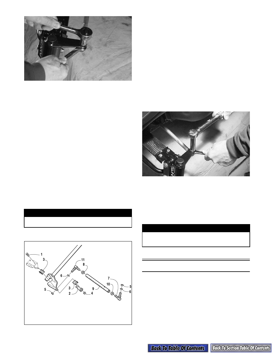
2. Remove the tie rod from the steering post (see

steps 10-12 of Steering Post (120 cc) - Removing

sub-section).

3. Loosen the jam nuts securing the tie rod; then

remove the ball joints from the tie rod. Slide the tie

rod from the steering boot.

CLEANING AND INSPECTING

„

NOTE: Whenever a part is worn excessively,

cracked, or damaged in any way, replacement is
necessary.

1. Inspect the ball joints and tie rods for damaged

threads or wear.

2. Inspect the ball joints and tie rods for cracks or

unusual bends.

3. Wash the ball joint in parts-cleaning solvent. Dry

with compressed air. Inspect the ball joint pivot

area for wear. Apply a low-temperature grease to

the ball joint.

ASSEMBLING AND INSTALLING

735-373A

1. Slide the tie rod through the steering boot; then

install the jam nuts and thread the ball joints onto

the tie rod.

„

NOTE: Each jam nut and ball joint is either a

right-hand or left-hand thread; therefore, each can
only be installed on one end of the tie rod. The
right-hand thread is the inside ball joint and jam
nut.

2. Secure the tie rod to the steering post. Tighten to

2.5-2.8 kg-m (18-20 ft-lb).

3. Secure the steering post to the front end (see steps

3-5 of Steering Post (120 cc) - Installing sub-

section).

4. Secure the tie rod to the spindle with a lock nut.

Tighten to 2.5-2.8 kg-m (18-20 ft-lb).

A034

„

NOTE: The ball joint must be installed on the

bottom side of the spindle arm.

5. Lock the jam nuts against the tie rod; then adjust

ski alignment (see appropriate Ski Alignment in

this section).

Front Tie Rods

REMOVING AND DISASSEMBLING

1. Remove the lock nut securing the tie rod to the

spindle. Account for a washer and O-ring.

„

NOTE: Note whether the tie rod is installed on

the top side or on the bottom side of the spindle
arm for installing purposes.

! WARNING

Always wear safety glasses when using com-
pressed air.

KEY

1. Cap Screw
2. Bearing 

Retainer

3. Bearing

4. Lock Nut
5. Lock Nut
6. Washer
7. Tie Rod End

8. Hex Nut
9. Tie Rod

10. Hex Nut
11. Tie Rod End

! WARNING

Neglecting to lock the jam nuts against the tie rod
may cause loss of snowmobile control and possible
personal injury.

7-17

7

AL108

AL655D

2. Remove the self-tapping screws or rivets securing

the steering boot and retainer to the front end.

3. Turn the handlebar in the appropriate direction;

then remove the cap screw and lock nut securing

the steering arm to the drag link. Account for

washers.

4. Loosen the jam nut securing each ball joint to the

tie rod; then remove the ball joints from the tie

rod. Slide the rod from the steering boot. Remove

the jam nuts from the ball joints.

CLEANING AND INSPECTING

„

NOTE: Whenever a part is worn excessively,

cracked, or damaged in any way, replacement is
necessary.

1. Inspect the ball joints and tie rods for damaged

threads or wear.

2. Inspect the ball joints and tie rods for cracks or

unusual bends.

3. Wash the ball joints in parts-cleaning solvent. Dry

with compressed air. Inspect the ball joint pivot

area for wear. Apply a low-temperature grease to

the ball joints.

ASSEMBLING AND INSTALLING

1. Slide the tie rod through the steering boot and

retainer; then install the jam nuts on the ball joints

and thread the ball joints onto the tie rod.

„

NOTE: Each jam nut and ball joint is either a

right-hand or left-hand thread; therefore, each can
only be installed on one end of the tie rod. The
right-hand thread is the inside ball joint and jam
nut.

2. Secure the tie rod to the ball joint on the forked

end of the drag link with a cap screw, washers, and

lock nut. Tighten to 2.8 kg-m (20 ft-lb).

3. Secure the steering arm to the drag link with a cap

screw, lock nut, and washers. Tighten to 4.2 kg-m

(30 ft-lb).

4. Position an O-ring and washer on the ball joint

assembly (threads coated with green Loctite

#609). Install the ball joint on the spindle arm as

noted in removing; then secure with a lock nut.

Tighten to 3.5 kg-m (25 ft-lb).

AL108

AL655D

5. Place the steering boot and retainer into position

and secure with self-tapping screws or rivets.

6. Adjust ski alignment (see appropriate Ski Align-

ment in this section).

! WARNING

Always wear safety glasses when using com-
pressed air.

7-18

7. Apply blue Loctite #242 to the jam nut threaded

area and tighten the jam nuts against the tie rod to

1.7-2.1 kg-m (12-15 ft-lb).

Spindle

(120 cc)

REMOVING

1. Position the front of the snowmobile up onto a

safety stand.

2. Remove the ski.

3. Remove the lock nut securing the tie-rod ball joint

to the spindle (account for the washer); then

remove the ball joint from the spindle.

A028

4. Remove the cap screw and lock nut securing the

shock to the spindle. Account for two shock

bushings.

AO166

5. Remove the two cap screws and lock nuts securing

the spindle to the suspension A-arms. Account for

all mounting hardware.

A0165

6. Inspect the tie-rod ball joint in place. If damage,

wear, or unusual bends are noted, loosen the jam

nut; then remove the ball joint from the tie rod.

INSPECTING

„

NOTE: Whenever a part is worn excessively,

cracked, or damaged in any way, replacement is
necessary.

1. Inspect the spindle for excessive wear, cracks,

bends, or imperfections.

2. Inspect all welds for cracking.

3. Inspect the suspension A-arm axle area for wear.

4. Secure the spindle in a vise. Rotate the spindle

clockwise and counterclockwise. The movement

should be smooth and free. If the spindle

movement is rough or binding, grease the spindle

with a good low-temperature grease. Rotate the

spindle. If the movement remains rough, replace

the spindle.

„

NOTE: When greasing the spindle, use enough

grease so that it can be seen coming out at both
the top and bottom of the spindle.

5. Inspect the spindle axle for wear, damage, or loose

fit.

INSTALLING

1. Place the shock mounting bracket into position on

the spindle; then place the A-arms into the spindle.

Secure with cap screws and lock nuts. Tighten

securely.

! WARNING

Neglecting to lock the jam nuts against the tie rod
may cause loss of snowmobile control and possible
personal injury.

7-19

7

AO165

2. Place the tie-rod ball joint into position on the

bottom side of the spindle arm and secure with a

lock nut (threads coated with blue Loctite #243)

tightened to 2.5-2.8 kg-m (18-20 ft-lb).

AO28

3. Place the lower shock eyelet w/shock bushings

into the shock mounting bracket. Secure with the

cap screw and lock nut. Tighten securely.

AO166

4. Install the ski.

5. Remove the safety stand from beneath the front

frame assembly.

Spindle

REMOVING

1. Position the front of the snowmobile up on a safety

stand.

2. Remove the ski.

3. Remove the lock nut and cap screw securing the

shock absorber to the spindle. Account for all

mounting hardware.

AL156D

4. Remove the lock nut securing the tie-rod ball joint

to the spindle (account for the washer and the O-

ring); then remove the ball joint from the spindle.

„

NOTE: Note whether the tie rod is installed on

the top side or on the bottom side of the spindle
arm for installing purposes.

AL158D


Content   ..  99  100  101  102   ..