Snowmobile Arctic Cat (2002 year). Manual - part 98


  Index      Snowmobiles / ATV     Snowmobile Arctic Cat - service manual 2002 year


Search            


Content   ..  96  97  98  99   ..


Snowmobile Arctic Cat (2002 year). Manual - part 98


7-4

3. Slide the end of the steering post into the lower

steering post bearing and place the upper end of

the steering post on the support.

A025

4. Place the upper steering post bearing into position

on the steering post and secure the steering post/

bearing assembly to the support with the bearing

retainer, cap screws, and lock nuts.

5. Tighten the upper and lower retainer cap screws

securely.

A026

„

NOTE: Check all fasteners to ensure they are

tight. Turn the handlebar full-left and full-right sev-
eral times to ensure free movement.

6. Apply Handlebar Adhesive (p/n 0636-071) to the

bore of the handlebar grip; then using a rubber

hammer, drive the grip into position.

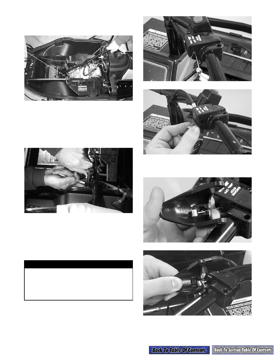
7. Place the emergency stop switch onto the right

handlebar and secure with the screw.

8. Route the throttle cable through the slot in the

throttle control and insert the cable end into the

throttle control. Secure the cable with a C-clip.

A981

A982

9. Seat each cable drum into its lever recess; then

secure each with a pin and C-clip.

A980

A999

! WARNING

The handlebar adhesive is extremely flammable.
This product contains acetone. The vapors
released can be easily ignited. Keep away from
heat, sparks, and open flame. Use only in a well
ventilated area. Avoid prolonged breathing of
vapor. Avoid eye and skin contact. Keep container
closed when not in use.

7-5

7

A979

Steering Post

(AWS III)

REMOVING

1. Tip the snowmobile on its side. Remove the

screws securing the skid plate.

2. Remove the two cap screws and lock nuts securing

the lower steering post bracket to the front end

assembly. Account for the two washers, bearing

caps, bearing halves, and washers.

AL046

3. Remove the cotter pin, cap screw, and lock nut

securing the steering arm to the steering post.

AL089

4. Tip the snowmobile upright. Remove the

handlebar pad.

5. Remove the four lock nuts and cap screws

securing the adjuster caps to the adjuster block;

then remove the caps. Place the handlebar

assembly to the side. Remove the adjuster block.

6. Remove the four machine screws securing the

console.

7. Remove the two cap screws and lock nuts securing

the steering post to the steering support. Account

for the backing plate, two washers, bearing caps,

bearing halves, and washers.

AL090

8. Carefully slide the steering post out of the chassis.

Be careful not to hook any wires or hoses.

INSPECTING

„

NOTE: Whenever a part is worn excessively,

cracked, or damaged in any way, replacement is
necessary.

1. Inspect all welded areas for cracks or deteriora-

tion.

2. Inspect the steering post and steering-post brackets

for cracks, bends, or wear.

3. Inspect the bearing halves, bearing caps, and

bearing housings for cracks or wear.

7-6

INSTALLING

0736-026

1. Carefully slide the steering post into position in

the chassis. Be careful not to hook any wires or

hoses.

2. On the upper end of the steering post, apply a light

oil to the bearing halves and place into position

around the steering post; then place the bearing

cap between the steering support and the steering

post. Place the bearing housing into position and

secure with two cap screws, washers, and lock

nuts. Tighten to 2.5 kg-m (18 ft-lb).

AL090

3. Secure the console with the machine screws. Make

sure all wiring connections are secure.

4. Place the adjuster block, handlebar assembly, and

adjuster caps into position; then secure with four

cap screws and lock nuts. Tighten lock nuts evenly

to 1.4 kg-m (10 ft-lb).

5. Install the handlebar pad.

6. Tip the snowmobile on its side. On the lower end

of the steering post, apply a light oil to the bearing

halves and place into position around the steering

post; then place the bearing cap and bearing

housing into position. Install the backing plate and

secure with two cap screws, washers, and lock

nuts. Tighten to 2.5 kg-m (18 ft-lb).

AL046

7. Place the tie rod into position. Secure with a cap

screw (coated with green Loctite #609) and lock

nut. Tighten to 4.2 kg-m (30 ft-lb). Install the

cotter pin and spread the pin.

AL089

8. Install the skid plate. Secure with screws.

„

NOTE: Turn the handlebar to the full-left and full-

right to ensure free movement.

KEY

1. Steering Post
2. Washer
3. Tie Rod Ball 

Joint

4. Cap Screw
5. Lock Nut
6. Cap Screw
7. Upper Bearing 

Housing

8. Steering Post 

Half Bearing

9. Bearing Cap

10. Adjuster Cap
11. Adjuster Block
12. Washer
13. Cap Screw
14. Lower Bearing 

Housing

15. Lock Nut

16. Backing Plate
17. Lock Nut
18. Tie Rod Ball 

Joint

19. Cotter Pin
20. Cap Screw
21. Hex Nut
22. Tie Rod Tube
23. Hex Nut

7-7

7

Steering Post

(AWS V)

REMOVING

1. Tip the snowmobile on its side. Remove the

screws securing the skid plate.

AL144D

2. Remove the cotter pin, cap screw, and lock nut

securing the tie rod to the steering post.

AL146D

3. Remove the two cap screws and lock nuts securing

the lower steering post bracket to the front end

assembly. Account for the backing plate, two

washers, bearing caps, bearing halves, and

washers.

AL145D

4. Tip the snowmobile upright. Remove the

handlebar pad.

AL136D

5. Remove the four lock nuts and cap screws

securing the adjuster caps to the adjuster block;

then remove the caps. Place the handlebar

assembly to the side. Remove the adjuster block.

AL147D

6. Remove the Phillips-head screws securing the

console to the gas tank.

AL142D

7. Remove the two cap screws and lock nuts securing

the steering post to the steering support. Account

for the two washers, bearing caps, bearing halves,

washers, and backing plate.


Content   ..  96  97  98  99   ..