Snowmobile Arctic Cat (2002 year). Manual - part 55


  Index      Snowmobiles / ATV     Snowmobile Arctic Cat - service manual 2002 year


Search            


Content   ..  53  54  55  56   ..


Snowmobile Arctic Cat (2002 year). Manual - part 55


4-13

4

AH618D

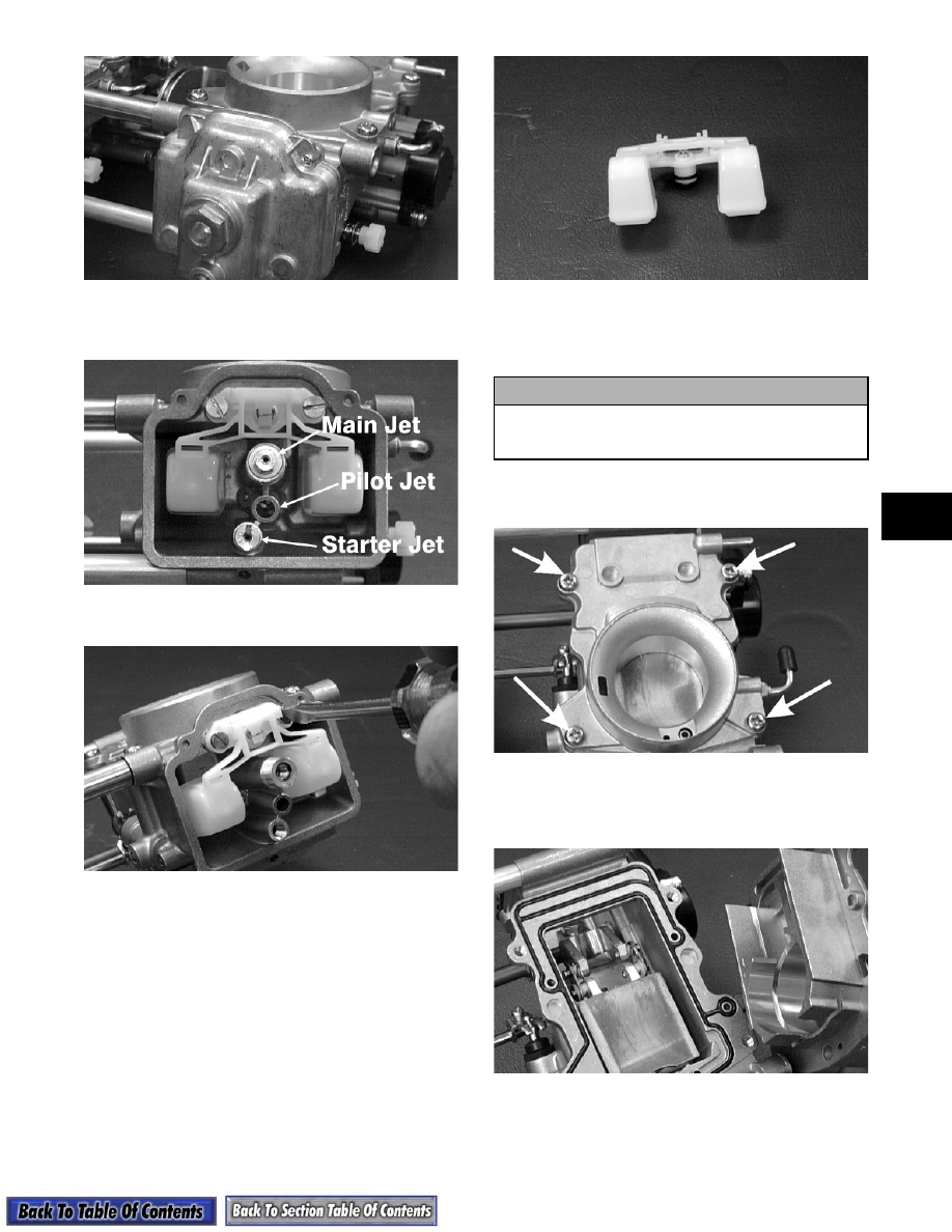
5. Remove the main jet (with washer), pilot jet, and

starter jet.

AH619DA

6. Remove the screws securing the float assembly.

AH620D

7. Remove the float assembly by lifting it up and out

of the mixing body. Account for the O-ring.

AH621D

„

NOTE: It may be necessary to use a spray lubri-

cant such as WD-40 to aid in removing the float
assembly.

8. Remove the Phillips-head screws securing the

funnel assembly to the mixing body.

AH622DA

9. Move the throttle lever to the full-open position;

then remove the funnel assembly. Account for the

gasket.

AH623D

10. Move the throttle lever slightly open; then rotate

the throttle valve out of the mixing body.

! CAUTION

To remove the throttle valve, the jet needle must
be removed or damage to the jet needle will
result.

4-14

AH624D

11. While counting the rotations for installing

purposes, rotate the fuel mixture screw clockwise

until lightly seated; then remove the mixture

screw. Account for a rubber washer, washer,

spring, and cap.

AH626D

„

NOTE: In the following step, only one E-clip

needs to be removed to free the throttle valve from
the lever assembly.

12. Remove the E-clip securing the plate to the throttle

valve; then slide the throttle valve to one side and

remove. Account for the plate, washer, clip, and

bushings.

AH627D

AH628D

Cleaning Carburetor

1. Place all metallic components in a wire basket and

submerge in carburetor cleaner.

2. Soak for approximately 30 minutes; then rinse

with fresh parts-cleaning solvent.

3. Wash all non-metallic components with soap and

water. Rinse thoroughly.

4. Dry all components with compressed air only

making sure all holes, orifices, and channels are

unobstructed.

5. Blow compressed air through all hoses to remove

any obstructions.

! CAUTION

Do not force a mixture screw when seating.
Forcing a mixture screw may result in damage to
the screw taper and/or mixing body.

! CAUTION

DO NOT place any non-metallic components in
parts-cleaning solvent or carburetor cleaner
because damage or deterioration will result.

! WARNING

Always wear safety glasses when drying compo-
nents with compressed air.

! CAUTION

DO NOT use wire or small drill bits to clean
carburetor orifices, holes, or channels. Distorted
or damaged orifices, holes, or channels can
result in poor carburetor operation.

4-15

4

Inspecting Carburetor

„

NOTE: Whenever a part is worn excessively,

cracked, or damaged in any way, replacement is
necessary.

1. Inspect the mixing body for cracks, nicks, stripped

threads, and any other imperfections in the casting.

2. Inspect the piston/throttle valve for cracks, score

marks, or imperfections in the casting.

3. On the VM-style, inspect the condition of the

piston valve spring.

4. Inspect the float for perforations or damage.

5. Inspect the gaskets, O-rings, and washers for

distortion, tears, or noticeable damage.

6. When applicable, inspect the tips of the idle speed

screw, jet needle, pilot air screw, needle valve, and

fuel mixture screw for wear, damage, or distortion.

„

NOTE: On the VM-style when inspecting the inlet

needle, inspect the side guides and tip for wear. If
the guides show any sign of wear, replace the inlet
needle.

7. Inspect the pilot jet and main jet for obstructions

or damage.

8. Inspect the starter plunger and seat for wear or

damage.

9. Inspect the carburetor mounting flanges for

damage and tightness.

10. On the TM-style, inspect the throttle shaft seal for

damage and signs of leaking.

11. On the BV-style, place the carburetor insulator on

a surface plate covered with #400 grit wet-or-dry

sandpaper. Move the insulator over the surface

plate using a figure eight motion. The motion

should produce an even wear pattern over the

entire sealing area.

A739

12. On the BV-style, inspect the condition of the

throttle return spring.

Assembling Carburetor

(BV-Style)

1. Install the nozzle and main jet into the carburetor

tower.

GF326D

GF325D

2. Place the needle valve assembly and the float into

position and secure to the carburetor body with the

pin.

! CAUTION

An air leak between the carburetor and engine
will cause a lean condition and severe engine
damage will result.

! CAUTION

Water or parts-cleaning solvent must be used in
conjunction with the wet-or-dry sandpaper or
damage to the sealing surfaces may result.

4-16

GF324D

GF323D

3. Install the splash ring onto the carburetor tower.

GF322D

4. Secure the float chamber to the carburetor with the

drain bolt.

GF321D

5. Install the pilot jet.

GF320D

6. Install the high-speed adjuster screw and rotate the

screw clockwise until lightly seated; then rotate

the screw counterclockwise the proper number of

rotations as noted during disassembling.

GF319D

Assembling Carburetor

(VM-Style)

1. Install the idle speed screw and spring.

B351

2. Install the pilot air screw and spring. Rotate

clockwise until lightly seated; then turn

counterclockwise the same number of turns as

noted in disassembling for an initial setting.


Content   ..  53  54  55  56   ..