Snowmobile Arctic Cat (2002 year). Manual - part 14


  Index      Snowmobiles / ATV     Snowmobile Arctic Cat - service manual 2002 year


Search            


Content   ..  12  13  14  15   ..


Snowmobile Arctic Cat (2002 year). Manual - part 14


2-39

2

AJ046

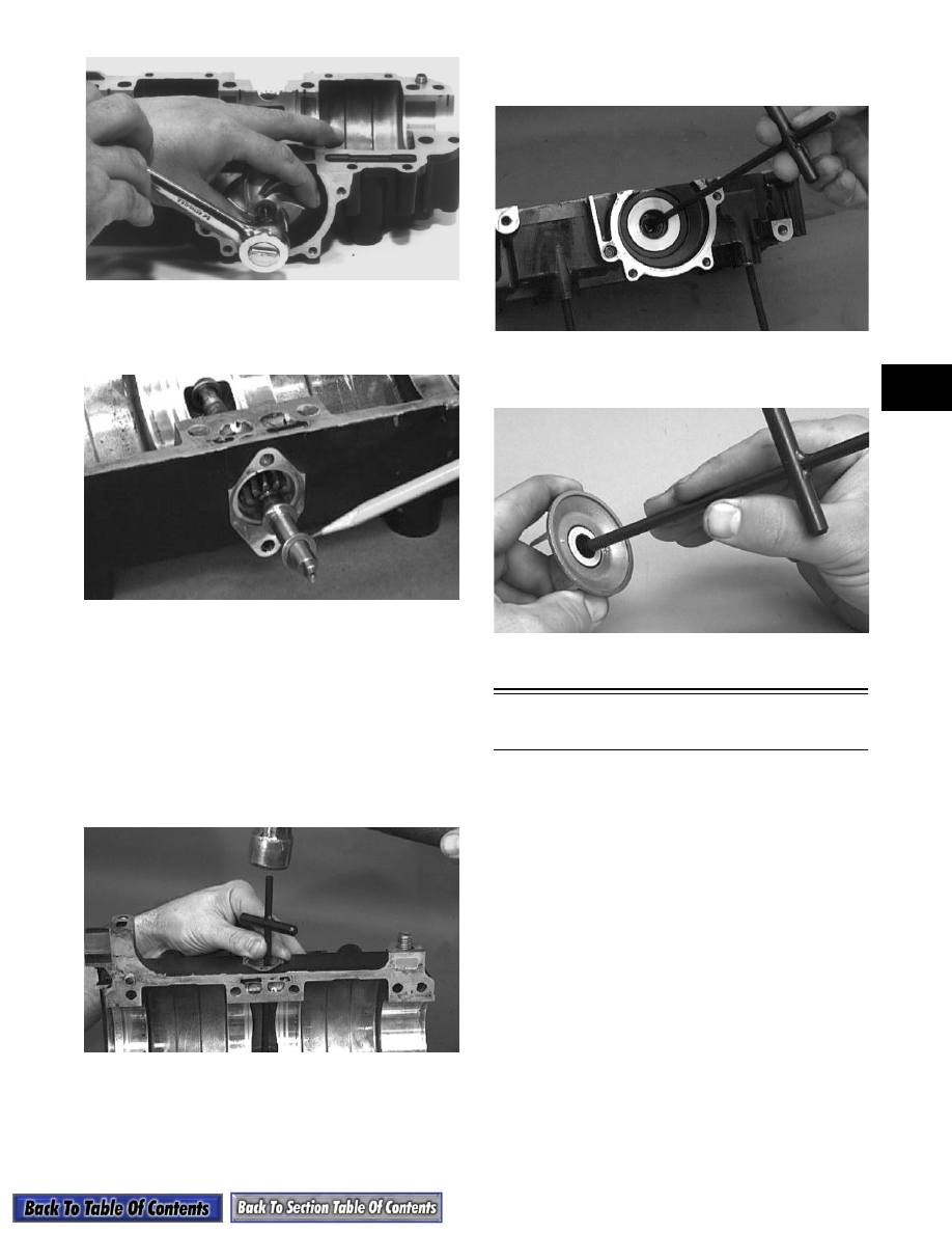
28. Remove the oil-injection pump/water pump

driveshaft from the lower crankcase half. Account

for the thrust washer on the outer end of the shaft.

AN324D

„

NOTE: Do not replace the inner seals unless the

water pump shows signs of leaking coolant out of
the small bleed hole in the bottom half of the
crankcase. If a water pump seal is to be replaced,
use the Water Pump Bearing and Seal Kit (p/n
0644-084).

29. Place the crankcase on the bench with the water

pump side down. Using the long seal driver, drive

the mechanical water pump seal from the

crankcase.

AN325D

30. Using a pair of snap ring pliers, remove the snap

ring securing the inner seal in the crankcase.

31. Using the hooked end of the tool, pull the inner

seal free of the crankcase.

AN326D

32. Using the hooked end of the tool, pry the seal ring

from the backside of the water pump impeller.

AN327D

Disassembling Engine

(600 cc Triple Model)

„

NOTE: If servicing the exhaust manifolds,

remove them at this time. 

1. Using an impact driver or a 6-mm hex wrench,

remove the four cap screws securing the magneto

case to the crankcase.

2. Using a spanner wrench to secure the crankshaft,

remove the cap screw, lock washer, and large flat

washer securing the flywheel.

3. Remove the three cap screws securing the starter

pulley to the flywheel.

4. To prevent damaging the crankshaft threads during

the flywheel removal procedure, install a

Crankshaft Protector Cap (p/n 0644-234) onto the

end of the crankshaft.

2-40

AN162

5. Attach the flywheel puller to the flywheel using

three 8-mm cap screws approximately 2 3/4 in.

long. Thread each of the three cap screws evenly

into the flywheel 1/2 in.

6. Tighten the center puller bolt against the

crankshaft protector on the end of the crankshaft.

Continue to tighten the puller bolt until the

flywheel snaps free of the crankshaft taper.

Remove the puller from the flywheel and place the

flywheel, open side up, on a clean work bench.

Account for the flywheel key.

AN161

7. Remove the three Allen-head cap screws securing

the stator to the stator plate.

8. Remove the rubber grommet from the crankcase

and slide the stator free of the crankshaft.

AN160

9. Remove the two Allen-head cap screws securing

the stator backing plate to the crankcase.

AN158

10. Remove the two screws securing the timing

sensor; then loosen the screw securing the wiring

harness retainer tab. Remove the timing sensor

from the crankcase.

AN157

11. Remove the nuts securing the APV covers to the

cylinders; then slide the covers back to expose the

valves.

AP134

12. Remove the cap screws securing the valves to the

cylinders; then remove the APV assemblies and

set them aside.

2-41

2

AP153

AP154

13. Remove the thermostat cover; then remove the

thermostat from the water manifold. Remove the

water manifold assembly.

„

NOTE: The thermostat is designed to open at

50°C (122°F). It should be checked for proper oper-
ation before installing (see Section 3).

AN156

14. Remove each cylinder head; then account for the

two O-rings under each head. For assembly

purposes, number the three heads and cylinders

using a marker. Start from the MAG-side.

AN209

15. Remove the four nuts securing each cylinder to the

crankcase; then carefully lift each cylinder straight

up and free of the piston. Support the piston as the

cylinder clears the piston to prevent the connecting

rod from dropping against the crankcase and

causing damage to the crankcase sealing surface.

Account for two alignment dowel pins per

cylinder.

AN207

16. For assembly purposes, number the dome of each

piston starting from the MAG-side; then remove

the MAG-side circlip from each piston.

AN242

17. Using Piston Pin Puller (p/n 0644-328), remove

the piston pin from each piston. Remove the

piston, piston pin bearing, and the two shim

washers. Keep each piston, piston pin, and bearing

together as a set.

2-42

AN241

18. Remove the cylinder base gaskets from the

crankcase. Note that the cylinder base gaskets are

aligned with the same dowel pins which align the

cylinders on the crankcase.

„

NOTE: If the cylinder base gaskets are not dam-

aged, they can be reused.

AN239

19. Remove the two screws securing the oil-injection

pump to the crankcase. Slide the pump free of the

crankcase. Account for the O-ring located around

the pump inner flange.

AQ130D

20. Remove the six cap screws securing the intake

flanges and reed valve assemblies to the

crankcase.

AN237

21. Remove each intake flange and reed valve

assembly. Be very careful not to damage the reed

valve stops. Place the assembly on its flat side.

Remove and discard and reed valve assembly

gasket.

AN236

22. Using an impact driver, remove the five screws

securing the water pump cover to the crankcase

and remove the cover. Account for the O-ring

gasket.

AN234

23. Loosen the cap screw securing the water pump

impeller until there is a 1/4-in. space between the

cap screw flange and impeller.


Content   ..  12  13  14  15   ..