Snowmobile Arctic Cat (2002 year). Manual - part 13


  Index      Snowmobiles / ATV     Snowmobile Arctic Cat - service manual 2002 year


Search            


Content   ..  11  12  13  14   ..


Snowmobile Arctic Cat (2002 year). Manual - part 13


2-35

2

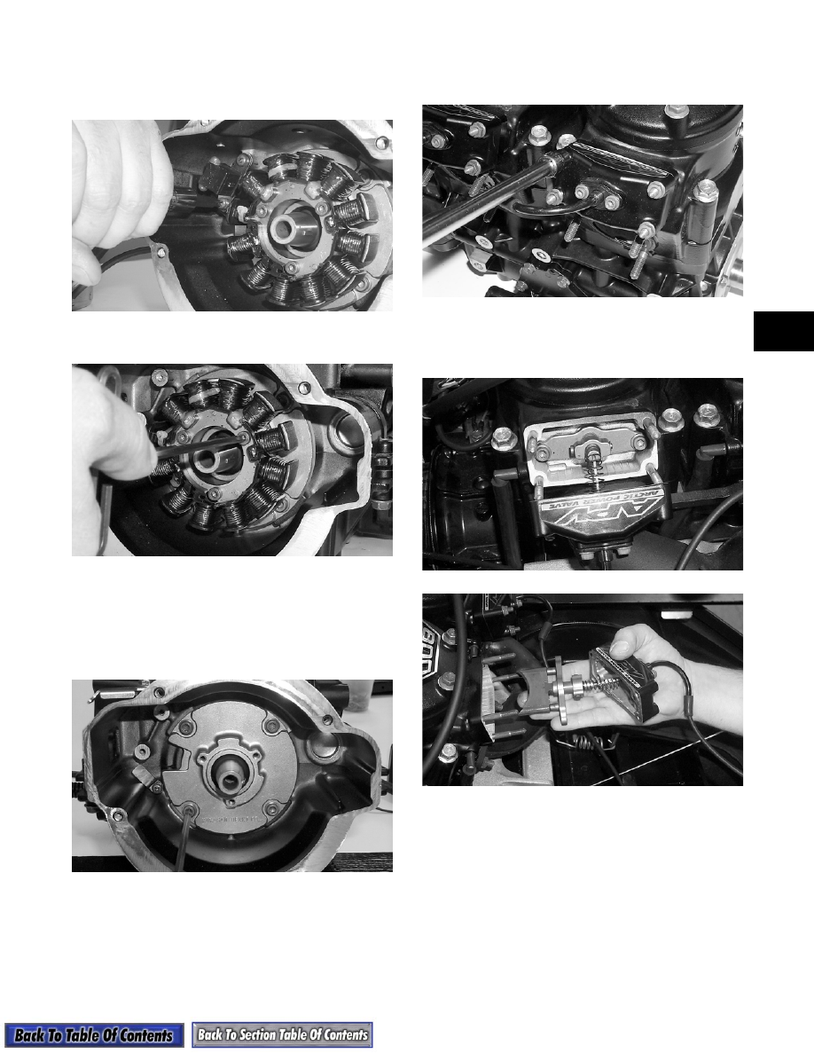
5. Remove the two screws securing the timing

sensor; then loosen the screws securing the wiring

harness retainer tab. Remove the timing sensor

from the crankcase.

AP131

6. Remove the cap screws securing the stator.

AP132

7. Remove the rubber grommet from the stator

wiring harness. Slide the stator free of the

crankshaft and remove.

8. Remove the cap screws securing the stator backing

plate. Remove the plate from the crankcase.

AP133

9. Remove the nuts securing the APV covers to the

cylinders; then slide the covers back to expose the

valves.

AP134

10. Remove the cap screws securing the valves to the

cylinders; then remove the APV assemblies and

set them aside.

AP120

AP121

11. Remove the three cap screws securing the

thermostat cap; then remove cap, rubber gasket,

and thermostat.

12. Remove the cap screws securing the thermostat

manifold to the cylinder heads. Remove the

manifold and discard the gaskets.

2-36

AP135

13. Remove the spark plugs.

14. Remove the cap screws and O-rings securing each

head; then separate each head from each cylinder.

Account for two O-rings beneath each head.

„

NOTE: Mark each cylinder head, cylinder, and

piston and keep together as an assembly. Mark the
MAG cylinder components #1 and the PTO cylinder
components #2.

AP136

„

NOTE: If servicing the intake flanges, remove

them at this time.

15. Remove the four cylinder base nuts and four

flange cap screws securing the cylinders to the

crankcase. Account for four flat washers and lock

washers. Using a rubber hammer, gently tap on the

side of each cylinder to free it from the crankcase.

AP137

16. Slowly lift each cylinder straight up and free of the

studs. Grasp the connecting rod and piston as the

cylinder clears the piston to prevent the rod from

dropping against the crankcase. Remove and save

the cylinder base gaskets.

AP138

17. Remove the PTO-side piston-pin circlip from the

PTO-side piston; remove the MAG-side piston-pin

circlip from the MAG-side piston.

AP140

18. Using the Piston Pin Puller (p/n 0644-328),

remove the piston pins from both pistons.

AP141

„

NOTE: For proper assembly, keep all MAG-side

components and all PTO-side components sepa-
rated. Assemble them on their proper sides.

2-37

2

19. Lift the pistons clear of the connecting rods and

account for two washers. Remove the small-end

connecting-rod bearings; then remove the piston

rings. Keep each piston with its rings; keep each

piston, pin, and bearing together as a set.

AQ059

20. Remove the four cap screws securing the PTO-end

plate to the crankcase; then remove the plate.

AP142

21. Remove the intake manifold and reed block

assemblies.

22. Remove either lower union bolt securing the lower

check valve assembly; then remove the two cap

screws securing the oil-injection pump to the

crankcase. Remove the pump, retainer, and two O-

rings.

AP143

23. Remove the six cap screws securing the water

pump cover to the crankcase. Remove the cover

and O-ring seal. Account for two dowel pins.

AP145

„

NOTE: Do not remove the water pump impeller

or the impeller shaft unless necessar y. Only
remove impeller and shaft if there are signs of
coolant leakage from the small hole located in the
bottom of the crankcase directly behind the water
pump housing.

24. Lay the engine on its side and remove the cap

screws securing the crankcase halves. Note the

position of the different-sizes cap screws for

assembling.

AP146

„

NOTE: On EFI models, the magneto case must

be removed prior to separating the crankcase
halves. 

! CAUTION

DO NOT use any type of punch to drive the pin
free of the piston; damage may result. Use a
piston-pin puller only.

2-38

25. Separate the crankcase halves by installing two

crankcase cap screws in opposite corners leaving

the heads approximately 6 mm (1/4 in.) out. Using

a plastic tipped hammer, tap on each cap screw

head until the case halves separate; then remove

the two cap screws. Lift the top half of the

crankcase off the bottom half. Grasp the

connecting rods as the top half of the crankcase is

removed. Do not allow them to drop onto the

sealing surface of the bottom case half.

26. Lift the crankshaft free from the crankcase half

and slide the crankshaft oil seals off the ends of the

crankshaft. Account for the C-ring. Slide the

bearings off the crankshaft. Remove and account

for the four bearing retaining pins and the two

crankcase dowel pins from the crankcase.

AP148A

A. Remove the O-ring from the oil-injection pump

retainer. Slide the retainer into position on the

shaft in the lower half of the crankcase.

B. While holding the retainer tight against the

crankcase, rotate the shaft. Bearing rotation

must feel smooth.

AJ044

C. If any roughness is felt, remove the retainer and

inspect its bearing by turning it several

revolutions. If it is smooth, the shaft must then

be removed and the inner bearing inspected.

Turn inner bearing by hand. If any roughness is

felt, replace the inner bearing.

D. Check the bottom of the water pump housing

for any signs of coolant leakage. The small

hole, located on the bottom of the crankcase

directly behind the water pump housing, will

show coolant stains if the seal has any leakage

problems. If stains or any signs of leakage are

present, remove impeller and shaft and replace

seals.

AJ045

„

NOTE: For instructions on bearing and seal

replacement, see the appropriate Assembling
Engine sub-section of this manual. Complete
steps 27-32 only if there is a bad seal or shaft bear-
ing.

27. Remove the cap screw securing the impeller to the

shaft.

! CAUTION

DO NOT drive any tool between halves to
separate the crankcase. Damage to the sealing
surfaces will result.

! CAUTION

DO NOT remove the water pump impeller or shaft
unless necessary. The shaft and impeller should
only be removed from the lower crankcase half
when there is a coolant leakage problem or a
rough inner bearing. To inspect for either
condition, follow steps A through D.


Content   ..  11  12  13  14   ..