Snowmobile Arctic Cat (2002 year). Manual - part 12


  Index      Snowmobiles / ATV     Snowmobile Arctic Cat - service manual 2002 year


Search            


Content   ..  10  11  12  13   ..


Snowmobile Arctic Cat (2002 year). Manual - part 12


2-31

2

AN414D

„

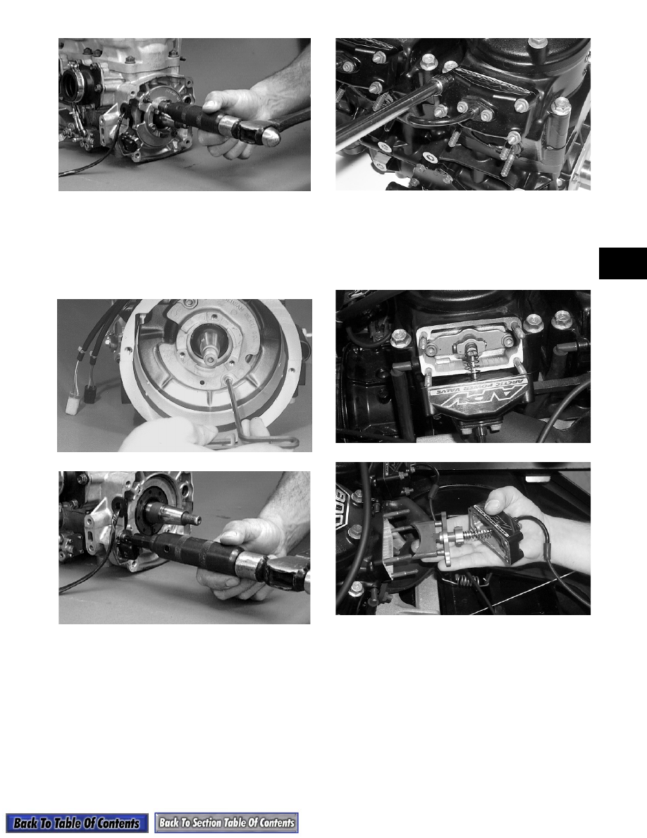
NOTE: The stator plate screws had Loctite

applied to the threads during assembly. Using an
impact driver, apply a sharp blow to the head of
each screw to break the Loctite loose before
removal.

7. Remove the ignition timing sensor.

AR107

AN415D

8. Remove the three cap screws securing the

thermostat cap; then remove the cap, gasket, and

thermostat.

9. Remove the nuts securing the APV covers to the

cylinders; then slide the covers back to expose the

valves.

AP134

10. Remove the cap screws securing the valves to the

cylinders; then remove the APV assemblies and

set them aside.

„

NOTE: The following illustrations are the 500 cc.

Other models may vary slightly.

AP120

AP121

11. Remove the spark plugs.

12. Remove the cap screws with O-rings securing the

cylinder head(s); then separate from the cylinders.

Account for the O-rings.

13. Remove the oil-injection hose from each cylinder

and the crankcase nozzle.

2-32

AN420D

14. Remove the eight nuts (with lock washers and

washers) securing the cylinders to the crankcase;

then using a rubber hammer, gently tap the

cylinders and remove from the crankcase by lifting

them straight up off their studs. Account for

gasket(s) and any alignment bushings.

15. Remove the PTO-side piston-pin circlip from the

PTO-side piston; then remove the MAG-side

piston-pin circlip from the MAG-side piston.

AN315D

16. Using the Piston Pin Puller (p/n 0644-328),

remove the piston pins from both pistons.

„

NOTE: For proper assembly, keep all MAG-side

components and all PTO-side components sepa-
rated. Assemble them on their proper sides.

AN316D

17. Lift the pistons clear of the connecting rods and

remove the small-end connecting-rod bearings

(account for two washers); then remove the piston

rings. Keep each piston with its rings; keep each

piston pin and bearing together as a set.

AN317D

„

NOTE: Place rubber bands over the connecting

rods and around the cylinder studs. This will pre-
vent the connecting rods from damaging the
crankcase.

18. Remove the intake flanges and reed valve

assemblies.

AN433D

! CAUTION

When removing a cylinder, be sure to support
the piston to prevent damage to the crankcase
and piston.

! CAUTION

DO NOT use any type of punch to drive the
piston pin free of the piston; damage may result.
Use a piston-pin puller only.

2-33

2

19. Remove either lower union cap screw securing the

lower check valve assembly; then remove the two

screws, lock washers, and washers securing the

oil-injection pump to the crankcase. Remove the

pump, retainer, and O-ring.

20. Remove the five screws securing the water pump

cover to the crankcase and remove the cover.

Account for the O-ring gasket.

21. Remove the cap screw securing the water pump

impeller; then slide the impeller free of the shaft.

22. Remove the cap screws securing the PTO-end

plate to the crankcase; then remove the plate.

23. Position the crankcase, with its bottom side up, on

two blocks of wood. Remove the cap screws

securing the crankcase halves.

24. Separate the crankcase halves by installing two

crankcase cap screws in opposite corners leaving

the heads approximately 6 mm (1/4 in.) out. Using

a plastic-tipped hammer, tap on each cap screw

head until the case halves separate. Remove the

cap screws.

AN045

25. Lift the bottom half of the crankcase off the top

half.

26. Lift the crankshaft free from the top half of the

crankcase and slide the crankshaft oil seals off the

crankshaft. Account for the C-ring. Remove the

bearing retaining pins and account for the

crankcase dowel pins.

27. Remove the oil-injection pump/water pump

driveshaft from the lower crankcase half. Account

for the thrust washer on the outer end of the shaft.

AN324D

„

NOTE: Do not replace the inner seals unless the

water pump shows signs of leaking coolant out of
the small bleed hole in the bottom half of the
crankcase. If a water pump seal is to be replaced,
use the Water Pump Bearing and Seal Kit (p/n
0644-084).

28. Place the crankcase on the bench with the water

pump side down. Using the long seal driver, drive

the mechanical water pump seal from the

crankcase.

AN325D

29. Using a pair of snap ring pliers, remove the snap

ring securing the inner seal in the crankcase.

30. Using the hooked end of the tool, pull the inner

seal free of the crankcase.

AN326D

31. Using the hooked end of the tool, pry the seal ring

from the backside of the water pump impeller.

! CAUTION

DO NOT drive any tool between halves to
separate the crankcase. Damage to the sealing
surfaces will result.

! CAUTION

Care must be taken to not allow the connecting
rods to drop onto the sealing surface of the
bottom case half.

2-34

AN327D

Disassembling Engine

(800 cc Models)

1. Using a spanner wrench to secure the flywheel,

remove the flywheel cap screw, lock washer, and

flat washer.

AJ012

2. Using a spanner wrench to secure the crankshaft,

remove the three cap screws from the starter

pulley. Remove the starter pulley.

AJ013

3. Install the Flywheel Puller Insert (p/n 0644-179)

into the end of the crankshaft.

AP130

4. Using Flywheel Puller (p/n 0144-310), remove the

flywheel from the crankshaft by tightening the

puller bolt, striking the head of the puller bolt with

a brass hammer, and tightening again. Repeat

procedure until the flywheel is free. Account for

the key in the crankshaft keyway.

AJ015

„

NOTE: To ensure the cleanliness of the flywheel

magnets, place the flywheel (with the magnets fac-
ing upward) on a clean bench.

! CAUTION

To prevent damage to the crankshaft, place a
puller insert into the crankshaft. The puller must
bottom on the insert and not on the crankshaft.
Also, do not thread puller bolts more then
12.7 mm (1/2 in.) into the flywheel. Damage to the
coils may result.

! CAUTION

When installing Flywheel Puller (p/n 0144-310), it
must be installed with its welded side facing
outward or the puller will be damaged.

! CAUTION

Before applying excessive pressure to the center
flywheel puller bolt, check to make sure puller
bolt is pulling straight. If it is pulling to one side,
the crankshaft will be damaged. Square the
puller using the three bolts that attach the puller
to the flywheel.


Content   ..  10  11  12  13   ..