Snowmobile Arctic Cat (2002 year). Manual - part 10


  Index      Snowmobiles / ATV     Snowmobile Arctic Cat - service manual 2002 year


Search            


Content   ..  8  9  10  11   ..


Snowmobile Arctic Cat (2002 year). Manual - part 10


2-23

2

AN047

„

NOTE: Do not replace the inner seals unless the

water pump shows signs of leaking coolant out of
the small bleed hole in the bottom half of the
crankcase. If a water pump seal is to be replaced,
use the Water Pump Bearing and Seal Kit (p/n
0644-084) and see Cleaning and Inspecting Engine
in this section.

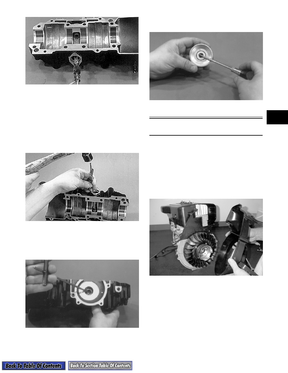
25. Place the crankcase on the bench with the water

pump side down. Using the long seal driver, drive

the water pump seal from the crankcase.

AN049

26. Remove the snap ring securing the inner seal in the

crankcase.

27. Using the hooked end of the tool, pull the inner

seal free of the crankcase.

AN050

28. Using a sharp, pointed tool, pry the seal ring from

the backside of the water pump impeller.

AN051

Disassembling Engine

(570 cc Models)

1.  Remove the exhaust manifold. Account for the

gaskets.

2.  Remove the nuts, lock washers, and washers

securing the intake flange assembly. Account for

the gaskets, insulators, and the heat deflector.

3.  Remove eight cap screws securing the main fan

shroud; then remove the shroud with the recoil

starter assembly.

MD0279

„

NOTE: Cap screws securing the front and rear

shrouds use special washers.

4. Remove the five cap screws securing the front

(exhaust-side) shroud to the cylinder head.

Account for the special washers.

2-24

MD0276

„

NOTE: Keep the special mounting hardware with

the shrouds for assembling purposes.

MD0065

5. Remove the spark plug grommets.

MD0060

6. Using Spanner Wrench (p/n 0144-007) to hold the

starter pulley, remove the cap screw securing the

flywheel to the crankshaft.

MD0282

7. Using Spanner Wrench (p/n 0144-007) to hold the

starter pulley, remove the three cap screws

securing the starter pulley and fan to the flywheel.

MD0000

8. Install Flywheel Puller Insert (p/n 0644-179) into

the end of the crankshaft. Using Flywheel Puller/

Spanner Wrench (p/n 0144-310) or suitable

substitute, remove the flywheel.

! CAUTION

To prevent damage to the crankshaft, install a
protective insert into the end of the crankshaft.
The puller must bottom on the insert and not on
the crankshaft. Also, do not thread puller bolts
more than five threads into the flywheel. Damage
to the stator coils may result.

2-25

2

AN615

„

NOTE: To ensure the cleanliness of the flywheel

magnets, place the flywheel (with the magnets fac-
ing upward) on a clean bench.

9. Remove the six cap screws securing the rear

(intake-side) shroud; then remove the shroud.

Account for the special washers.

MD0277

MD0067

10. Remove the rubber insulator grommet from the

crankcase; then remove two Phillips-head cap

screws securing the ignition timing sensor and pull

the wires through the hole in the crankcase. 

MD0075

MD0074

11.  Remove the three Allen-head cap screws securing

the stator and remove it along with the stator

wiring.

MD0072

2-26

MD0076

12. Remove the four Allen-head cap screws securing

the stator plate. Remove the stator plate.

MD0255

MD0078

13. Remove the four cap screws securing the seal

retainer plate on the PTO-side; then remove the

plate. 

MD0081

14. Remove the spark plugs.

MD0083

15. Remove the eight cap screws, two nuts, and two

washers securing the cylinder head to the

cylinders; then remove the cylinder head. Discard

the cylinder head gasket.

MD0289

16. Remove the four 6 mm nuts and eight 10 mm nuts

securing the cylinders to the crankcase.

„

NOTE: Using a felt-tip marker, mark the cylinders

as to MAG-side and PTO-side for assembling.
Also, mark the pistons at this time.


Content   ..  8  9  10  11   ..