Snowmobile Arctic Cat (2000 year). Manual - part 147
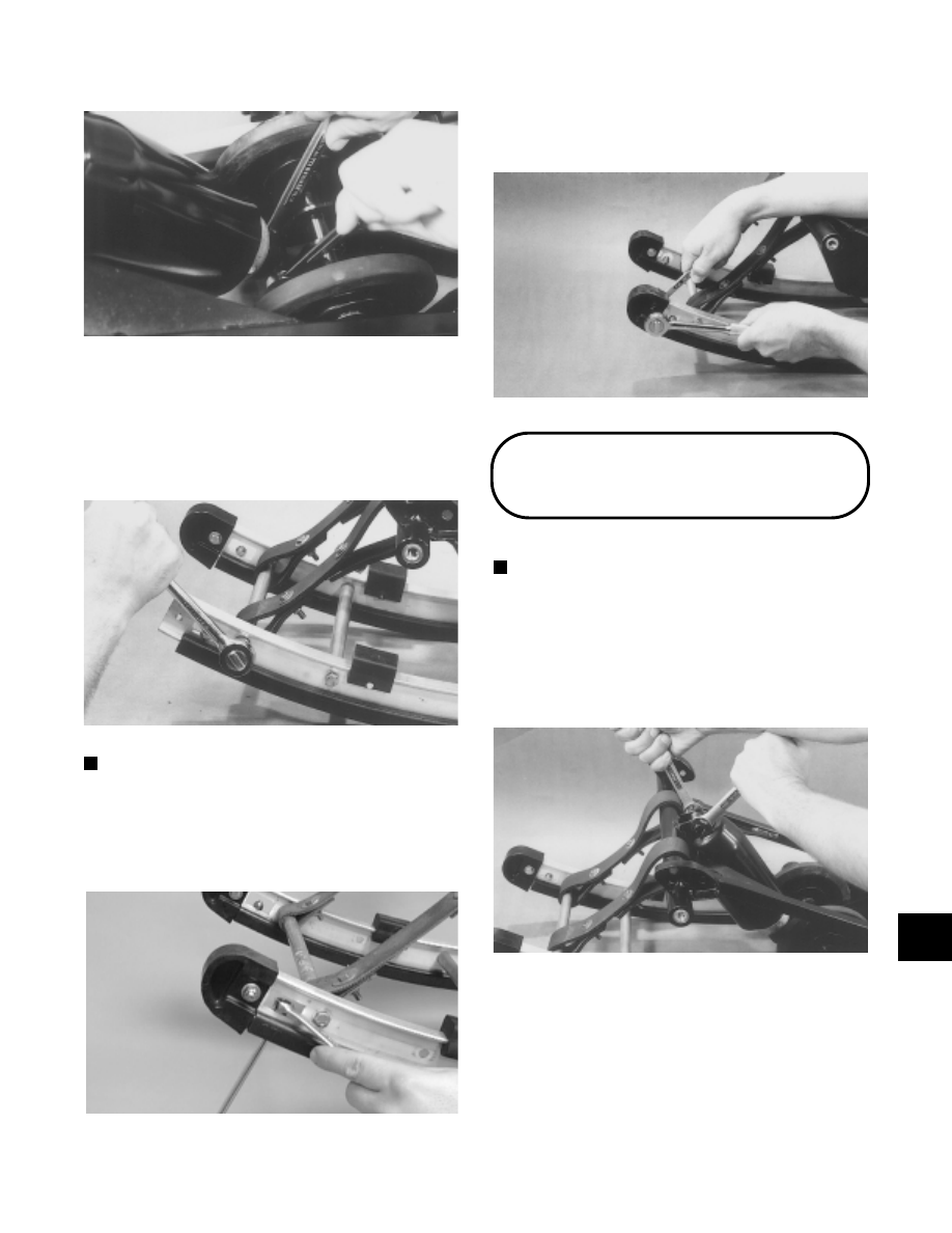
Fig. 9-415
AG317
7. Install the rubber shock pad on the slide rail and
secure with push pin and a new push nut.
8. Place both front crossbraces between the slide rails
and secure with four cap screws (coated with red
Loctite #271). Tighten to 2.4 kg-m (17 ft-lb).
Fig. 9-416
AG301
NOTE: Be sure to place the forward crossbrace
through the limiter straps.
9. Install the lock nut (threads coated with red Loctite
#271) securing the wear strip to the slide rail.
Tighten to 1.1 kg-m (8 ft-lb).
Fig. 9-417
AG298D
10. Place the end cap onto the rail and secure with cap
screw, washers, and lock nut. Tighten to 1.1 kg-m
(8 ft-lb).
Fig. 9-418
AG297
Front Arm Shock
Absorber
NOTE: The skid frame must be removed for this
procedure.
DISASSEMBLING
1. Remove the cap screw and lock nut securing the
upper shock absorber eyelet to the front arm.
Account for a bushing.
Fig. 9-419
AG306
2. Remove the cap screw and lock nut securing the
lower shock eyelet to the front shock bracket.
Remove the shock absorber and account for a
bushing.
9
9-111