Snowmobile Arctic Cat (2000 year). Manual - part 114
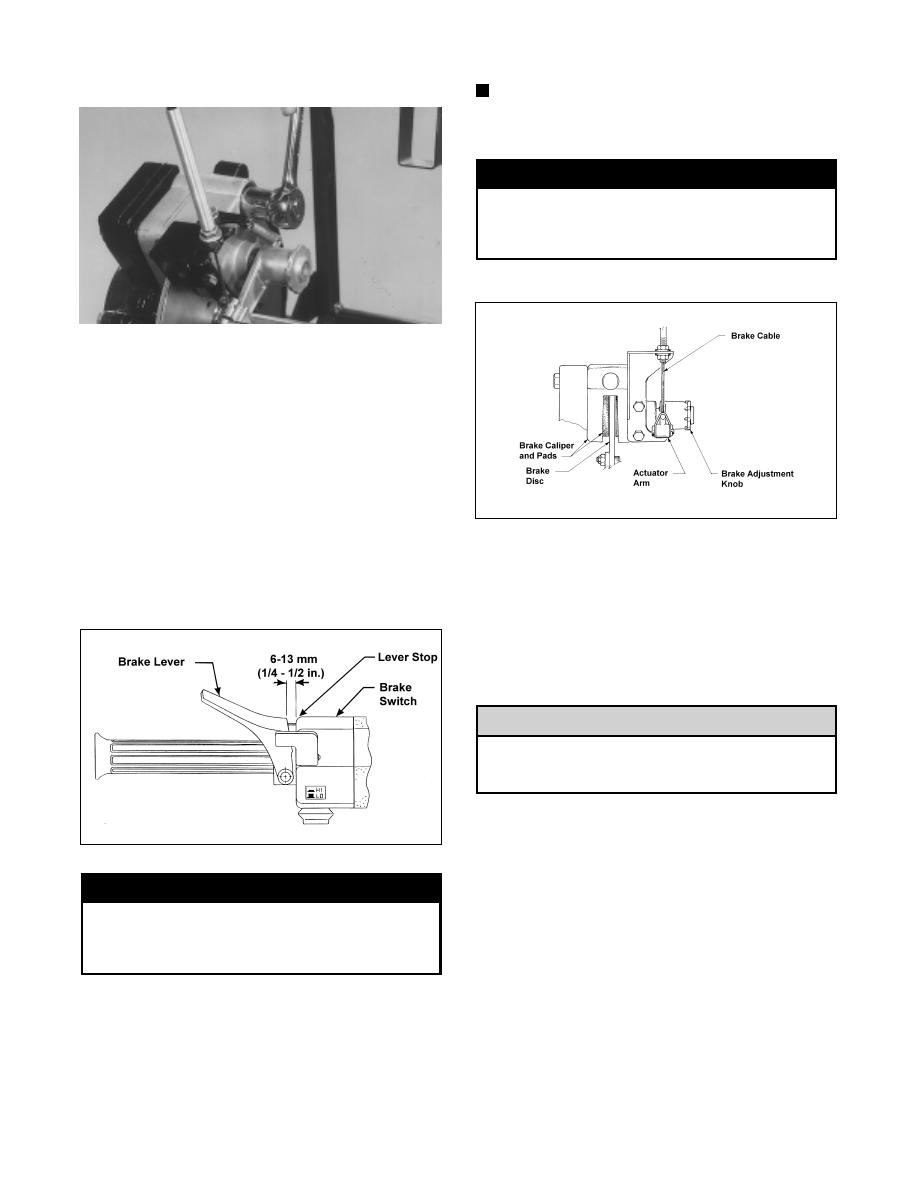
Fig. 8-246
AF298
8. Release the parking brake and recheck the brake
lever free-play (adjust as needed); then place the
recoil starter rope into the guide portion of the brake
cable bracket.
ADJUSTING BRAKE LEVER TRAVEL
1. Rotate the brake disc alternately forward and
backward while slowly compressing the brake
lever.
2. At the point where the disc is locked, check the
distance between the brake lever and lever stop. The
distance must be within a range of 6-13 mm
(1/4-1/2 in.).
Fig. 8-247
0727-451
! WARNING
Before making any adjustment, make certain the
brake quick-adjust knob isn’t hot. If the
snowmobile has just been used, allow some time
for the knob to cool or burns may result.
3. To decrease brake lever travel (set up brake), pull
out on the spring-loaded quick-adjust knob and
rotate the knob clockwise periodically checking the
brake lever travel distance until the correct travel
distance is attained. Once the correct brake lever
travel has been obtained, release the knob into a
secured position.
NOTE: If the quick-adjust knob has reached its
maximum adjustment (cannot be rotated any
further clockwise), both brake pads must be
replaced.
! WARNING
DO NOT attempt to adjust the brake with the
flange nuts on the brake cable bracket. Incorrect
brake adjustment may occur causing possible
brake failure.
Fig. 8-248
0730-151
4. To increase brake lever travel (loosen the brake),
pull out on the quick-adjust knob and rotate the
knob counterclockwise periodically checking the
brake lever travel. Once the desired brake lever
travel is obtained, release the knob into a secured
position.
REPLACING BRAKE PADS
The brake pads must be replaced as a set. Do not
under any circumstances ever replace only one
of the brake pads.
1. Using a 1/2-in. socket, remove the front brake
assembly guide pin. Slowly pull the pin from the
assembly and catch the alignment ball as it drops
from the hole in the front of the caliper assembly.
2. Remove the rear guide pin; then slide the brake
caliper assembly forward free of the brake disc.
3. Remove the stationary brake pad from the caliper
assembly.
4. Tip the caliper on its side and allow the movable
brake pad to drop free of the caliper assembly.
5. Place the new movable brake pad into position; then
temporarily secure with a rubber band to hold it in
place.
! CAUTION
8-62