Snowmobile Arctic Cat (2000 year). Manual - part 109
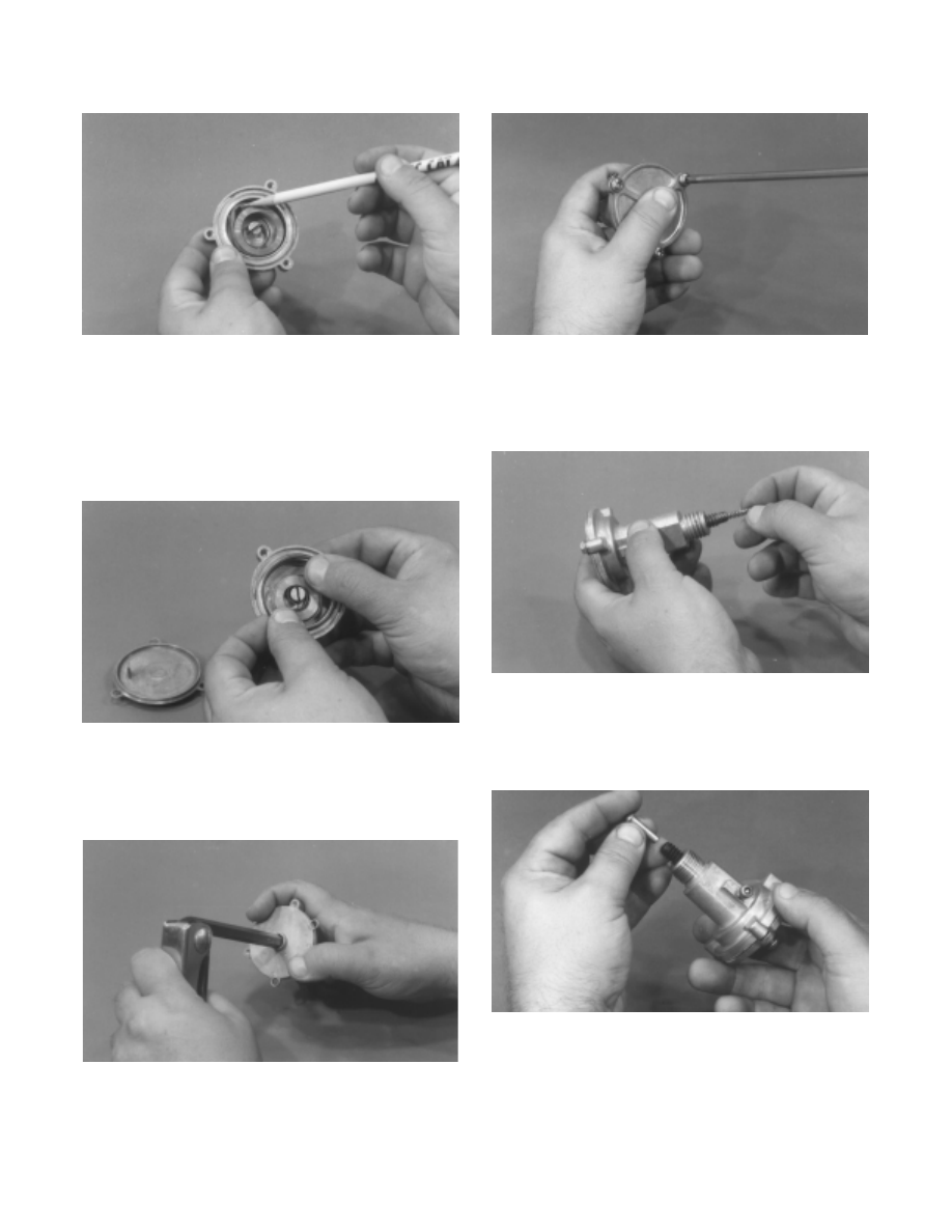
Fig. 8-152
AF406
5. With the spring in position, remove the cable tie
used to prevent it from unwrapping.
6. Place the O-ring seal into position; then set the end
cap into position. Make sure its tab is hooked into
the end of the spring.
Fig. 8-153
AF405
7. While holding the end cap down into position,
rotate the end cap 20 turns clockwise to tension the
spring.
Fig. 8-154
AF400
8. Install the three cap screws (coated with blue
Loctite #242) and tighten to 1 kg-m (7 ft-lb).
Fig. 8-155
AF419
9. Apply a thin coat of grease to the spring and place
the spring into position in the end of the adjuster
bolt.
Fig. 8-156
AF401
10. Use a thin coat of grease on the stem shaft to hold
it in position; then place the stem into the end of the
adjuster bolt.
Fig. 8-157
AF418
11. Securely tighten the adjuster assembly to the chain
case.
8-42