Snowmobile Arctic Cat (2000 year). Manual - part 110


  Index      Snowmobiles / ATV     Snowmobile Arctic Cat - service manual 2000 year


Search            


Content   ..  108  109  110  111   ..


Snowmobile Arctic Cat (2000 year). Manual - part 110


REMOVING CALIPER

1. Slide a piece of flexible tubing over the ball of the

bleeder valve and direct the other end into a
container.

Fig. 8-167

0730-434

2. Open the bleeder valve and compress the brake

lever several times to drain the reservoir of fluid.

3. Remove the brake hose from the caliper. Use an

absorbent towel  to collect any remaining brake
fluid.

Fig. 8-168

AF262D

Brake fluid is highly corrosive. Do not spill brake
fluid on any surface of the snowmobile.

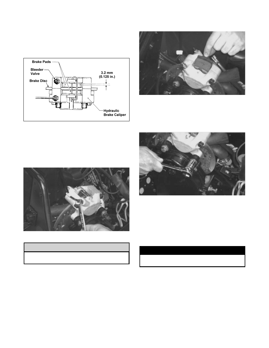
4. Remove the retaining pin securing the brake pads to

the caliper assembly; then remove the brake pads.

Fig. 8-169

AF255D

5. Loosen the upper socket-head cap screws securing

the caliper halves; then remove the two cap screws
and lock washers securing the brake caliper to the
chain case. Account for two spacer washers.

Fig. 8-170

AF261D

6. Remove the caliper assembly from the engine

compartment.

DISASSEMBLING

1. Position a piece of wood between the pistons. Using

low-pressure compressed air, blow into the caliper
brake hose fitting to remove the brake pistons.

! WARNING

Always wear safety glasses when using
compressed air.

! CAUTION

8-46

Fig. 8-171

AF248

2. Remove the two cap screws securing the caliper

halves. Account for the small O-ring.

3. Remove the piston O-rings and discard.

Fig. 8-172

AF264

CLEANING AND INSPECTING

NOTE: Whenever a part is worn excessively,

cracked, or damaged in any way, replacement is
necessary.

1. Inspect the brake pistons for gouges, cracks, pitting,

scuffing, or corrosion. If any of these conditions
exist, replace the piston.

2. Clean the piston outer surface by using a

Scotch-Brite pad and clean brake fluid as a cleaner.

Do not use any sharp cleaning tool on the piston
surface as it may cause damage. Parts-cleaning
solvent must not be used as it can damage the
piston O-ring.

Fig. 8-173

AF230

3. Inspect the brake caliper for gouges, cracks, pitting,

scuffing, or corrosion. If any of these conditions
exist, replace the caliper.

4. Clean the caliper inner wall surface using a soft

Scotch-Brite pad and clean brake fluid. Wipe
caliper wall clean with a clean rag and brake fluid.

Fig. 8-174

AF267

5. Inspect the condition of the brake pads. Replace if

damaged or worn. The brake pad thickness must be
greater than 3.2 mm (0.125 in.). If the brake pad
thickness is less than specified, replacement of both
pads is necessary.

6. Inspect the brake hose for cracks and deterioration

and check the condition of the threaded connectors.

! CAUTION

8

8-47

ASSEMBLING

Fig. 8-175

730-369A

1. Apply approved brake fluid to the new O-ring; then

install the O-ring into the groove of each caliper
half.

Fig. 8-176

AF251

NOTE: Always use a new O-ring when assembling

the brake caliper.

2. In each caliper half, apply approved brake fluid to

the brake piston; then while twisting, install the
piston with the open side facing out.

Fig. 8-177

AF266

Fig. 8-178

AF269

3. Place the small O-ring into position; then assemble

the two caliper halves. Secure with the two
socket-head cap screws. Do not tighten at this time.

Fig. 8-179

AF264

INSTALLING CALIPER

1. Secure the caliper assembly on the chain case using

two cap screws, lock washers, and spacer washers.
Tighten the cap  screws to 4.2 kg-m  (30 ft-lb).
Tighten the upper socket-head cap screws to 5 kg-m
(36 ft-lb).

Fig. 8-180

AF261D

2. Install the brake hose on the caliper and tighten

securely.

KEY

1. Retaining Pin
2. Cap Screw
3. Washer
4. Washer
5. Housing O-Ring
6. O-Ring
7. Piston
8. Bleeder Fitting
9. Brake Pad Set

10. Housing
11. Housing
12. Cap Screw
13. Lock Washer
14. Washer

8-48

Fig. 8-181

AF262D

3. Install the brake pads. Secure with the retaining

pin.

Fig. 8-182

AF255D

Fig. 8-183

AF237D

4. Bleed the brake system (see Bleeding Brake

System in this sub-section).

NOTE: If new brake pads were installed, a

“burnishing” process is required. Drive the
snowmobile slowly and compress the brake lever
repeatedly until the pads just start to heat up; then
allow them to cool down. This process stabilizes the
pad material and extends the life of the pads.

Brake Lever/Master

Cylinder Assembly

(Hydraulic System)

REMOVING

1. Slide a piece of flexible tubing over the ball of the

bleeder valve and direct the other end into a
container. Remove the reservoir cover; then open
the bleeder valve. Allow the brake fluid to drain
completely.

Fig. 8-184

0730-434

2. Using a small screwdriver, push in on the

self-locking tab; then slide the brakelight switch
free of the brake control.

Fig. 8-185

AF201D

3. Place an absorbent towel around the connection to

absorb brake fluid. Remove the brake fluid hose
from the master cylinder.

Brake fluid is highly corrosive. Do not spill brake
fluid on any surface of the snowmobile.

! CAUTION

8

8-49


Content   ..  108  109  110  111   ..